Well, the windows & frames have for the time being, Won!
I have set them aside and will think about an alternate method of attacking
these little baaa..bits!
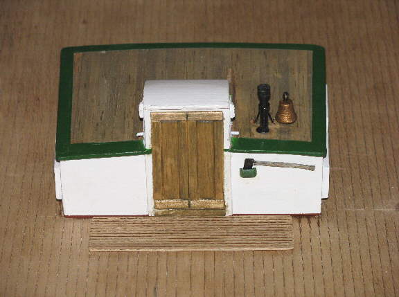
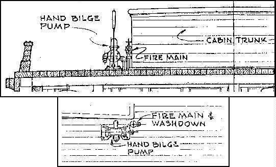
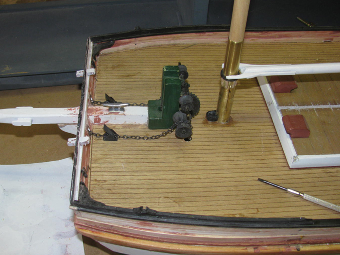
I have moved on to the manual deck bilge pump.
I have only to wait for the glue to dry so I can attach the pipes.
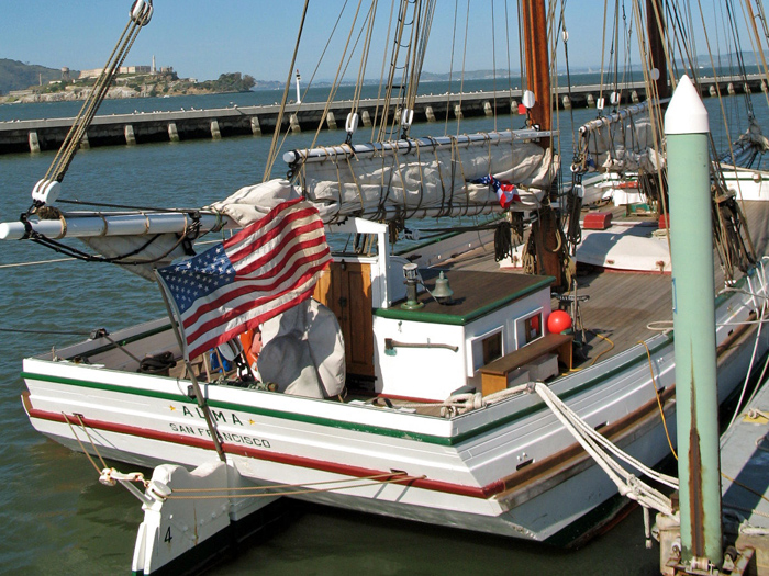
The Fire Main is an addition that was added during the 1968 restoration
of Alma. It will not be included.
Turns out I will be building the Fire Main pipe. I found it on my copy
of the original 1892 plans. It's not on all the plan pages.
Just on a couple with the cabin elevations.
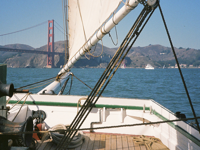
Then photos.
.
Photos
.
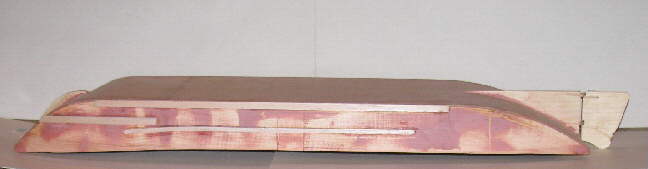
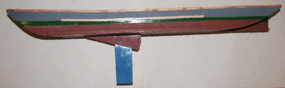
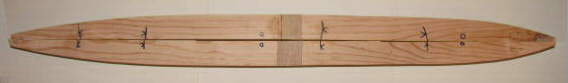
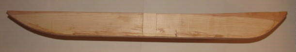
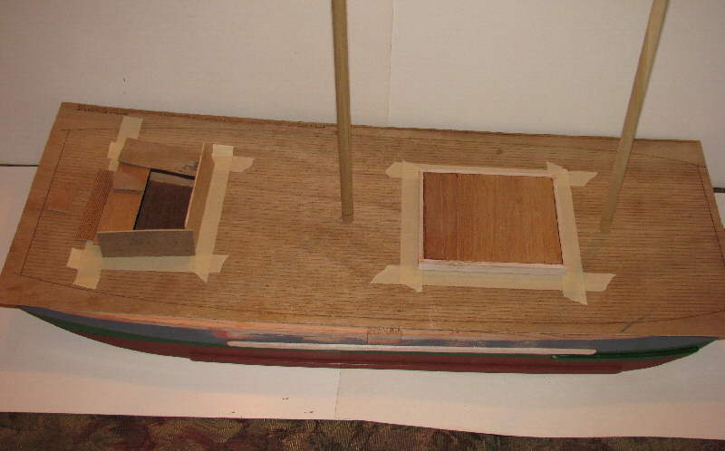
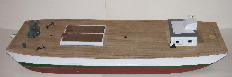
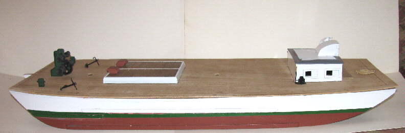
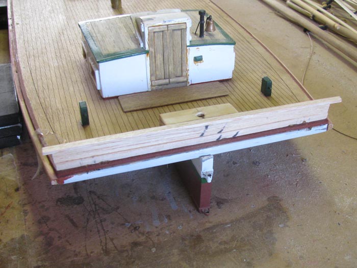
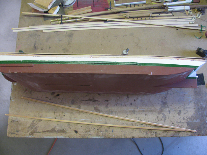
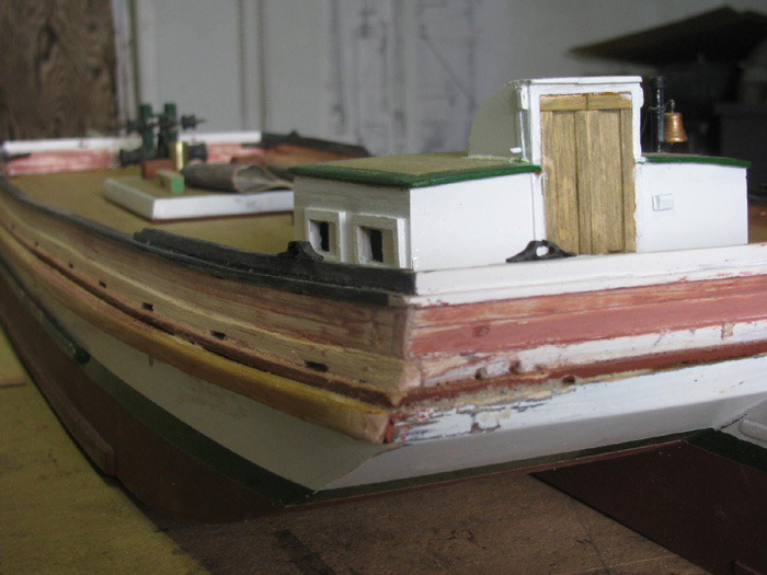
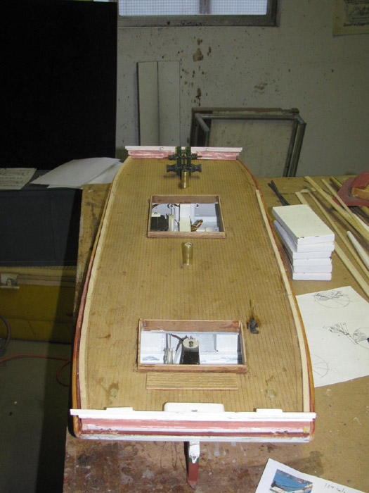
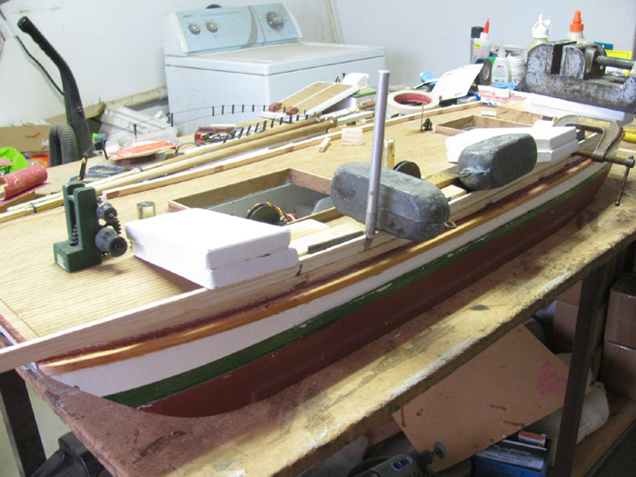
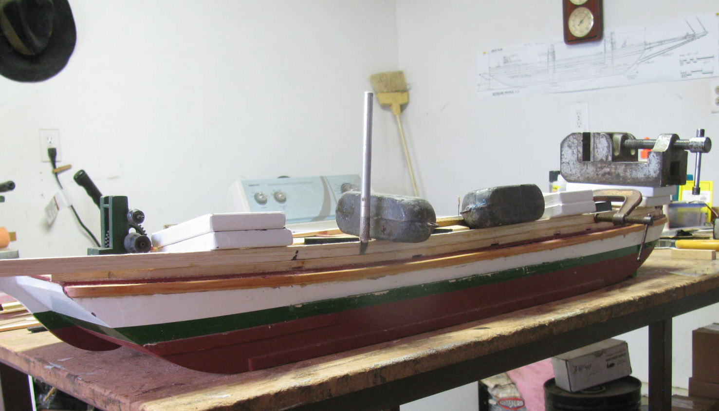
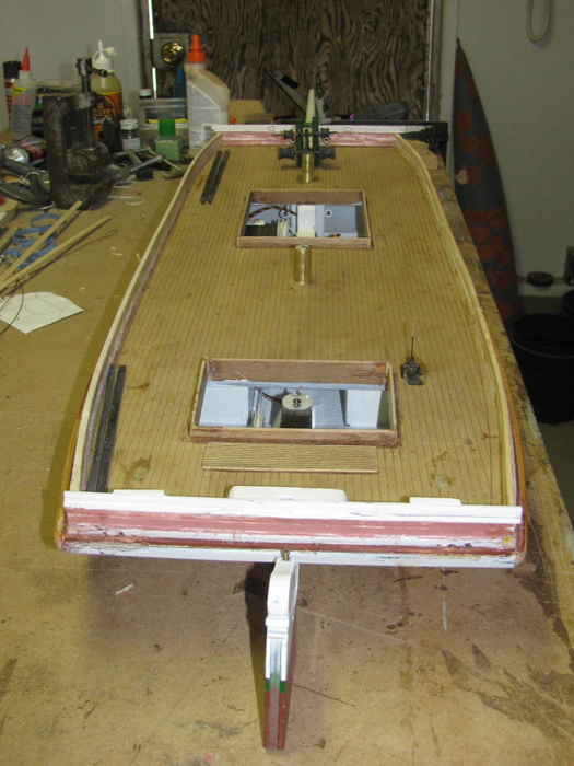
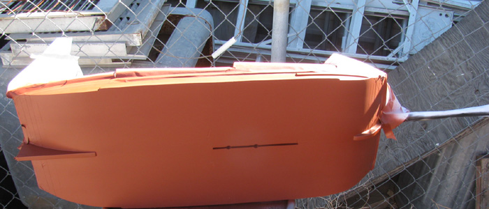
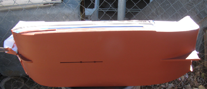
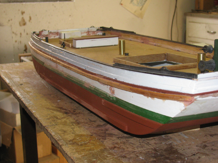
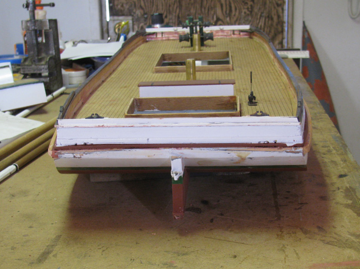
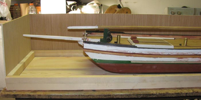
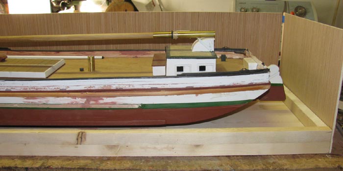
The deck has been trimmed to fit but is not mounted.
The lower hull is in the process of being painted as is the cabin.
The boat looks odd but I know that the plank railing is missing that
goes all the way around the deck.
The railing will be about 7/8" tall. The cargo hatch is 1/2" tall not
counting the vents.
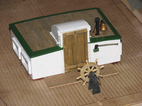
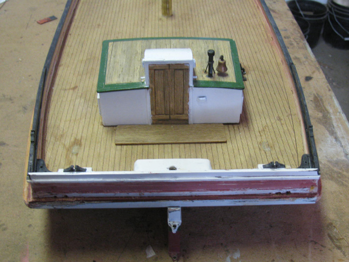
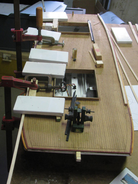
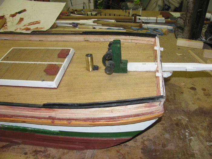
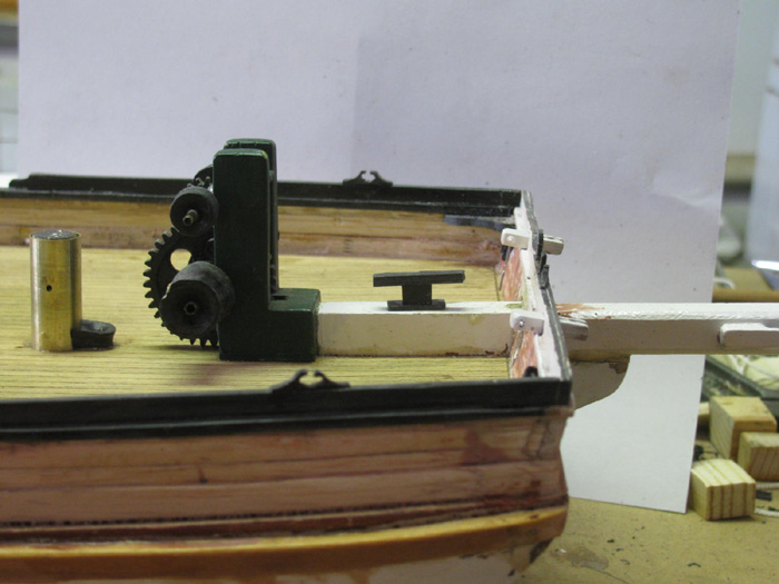
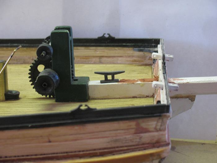
Finally back to work on the Alma.
Glues some assembles to the deck.
Got tired of them falling over and falling of the hull completely.
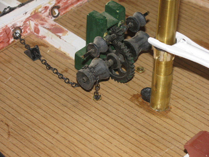
2 Steering bits
1 bilge pump
1 anchor winch
1 floor grate between cabin and wheel
=======================
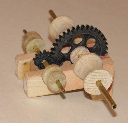
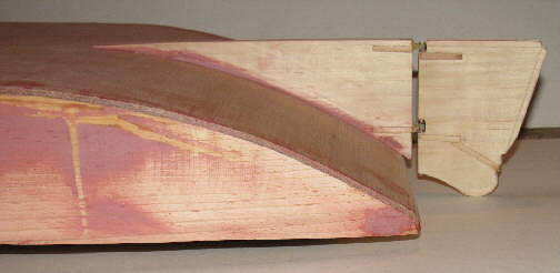
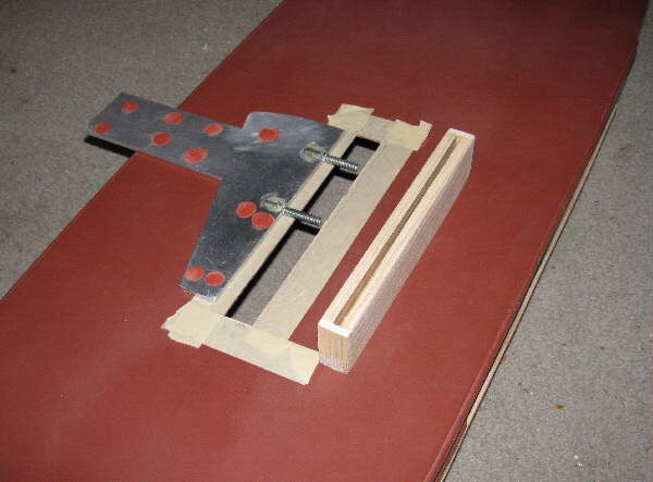
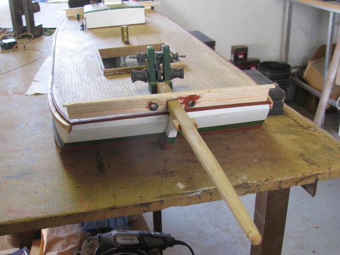
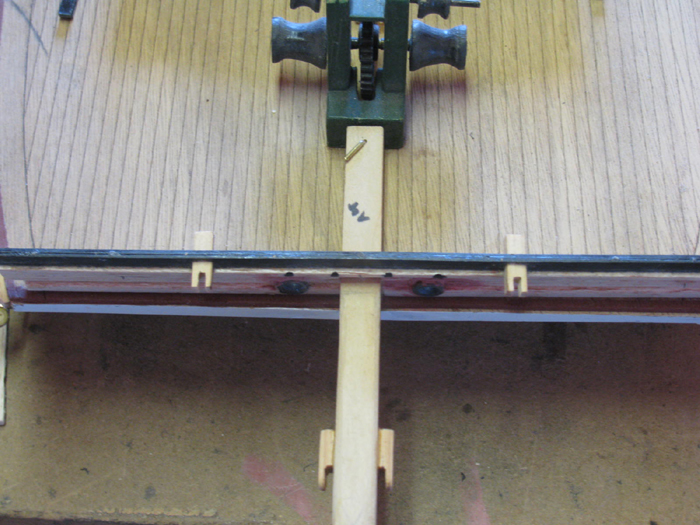
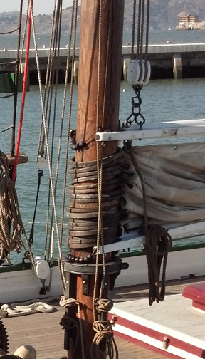
Working on the mast support.
This is to make removing the mast easier without having to remove any
rigging.
Under the deck are Mast Support blocks.
There is a brass tubing glued in to the Support Blocks.
The mast was originally full length that went in to the deck socket
and bottomed out.
But this required the mast to be lifted up 2.5" to remove.
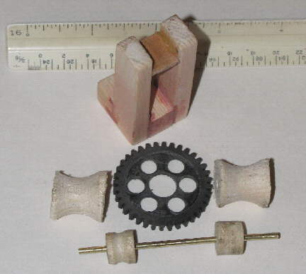
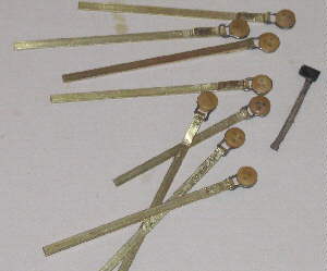
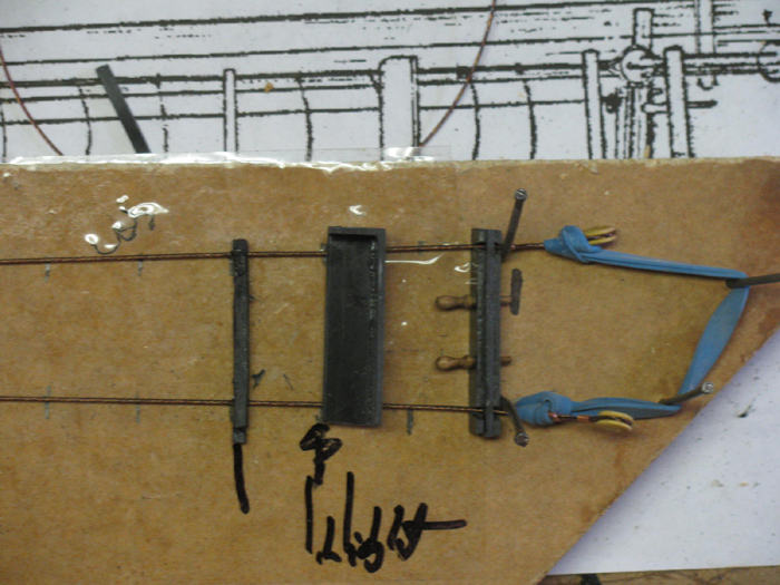
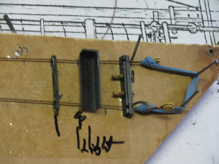
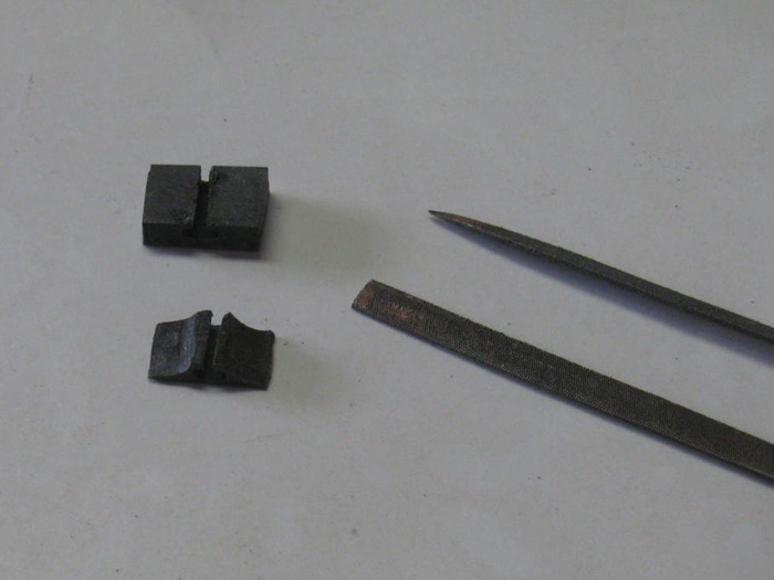
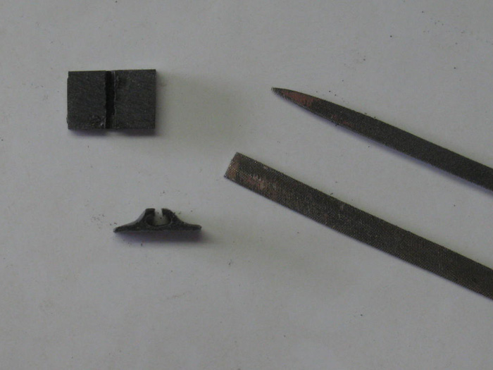
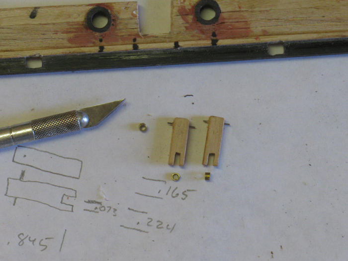
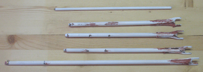
Here are some of the parts made to accomplish this.
The mast was cut flush with the top of the mast socket in the hull.
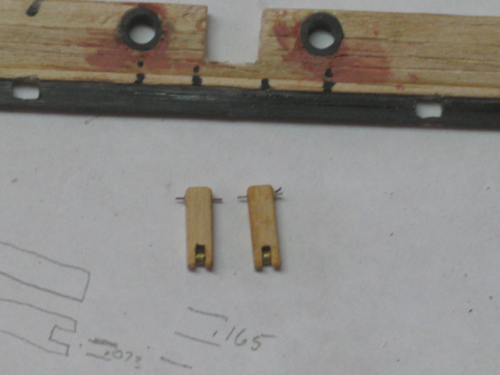
The bottom piece is a brass sleeve that goes over the mast and fits
inside the deck socket.
On the sleeve is a plastic part that is where bay laying pins will
be mounted.
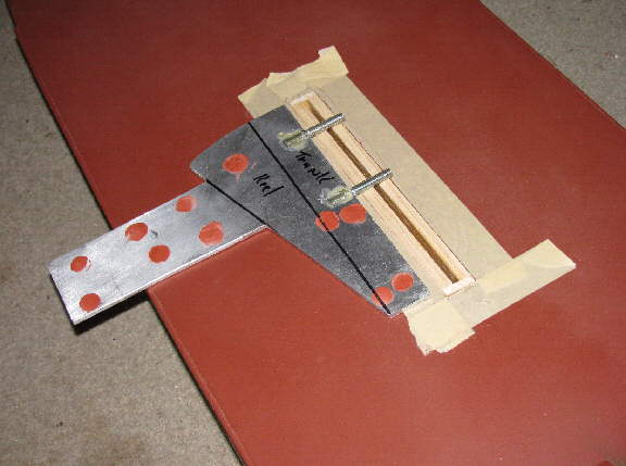
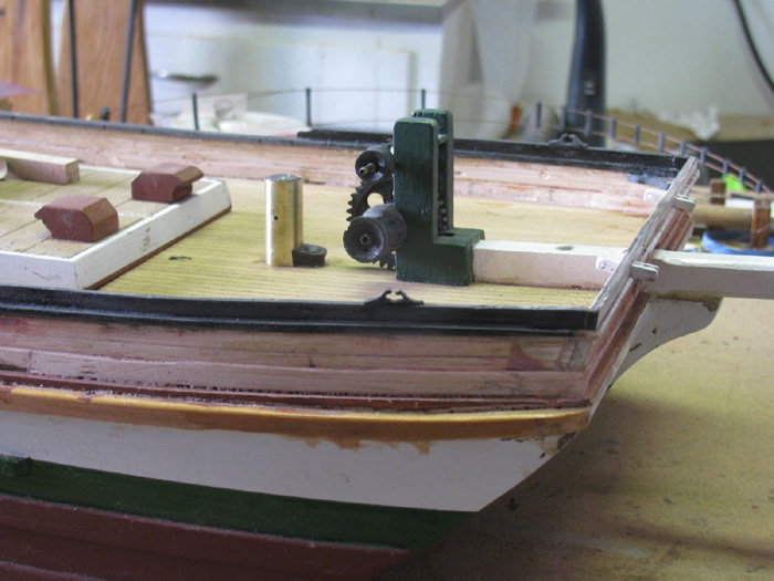
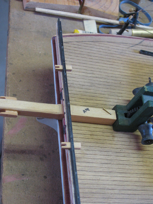
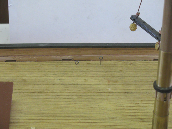
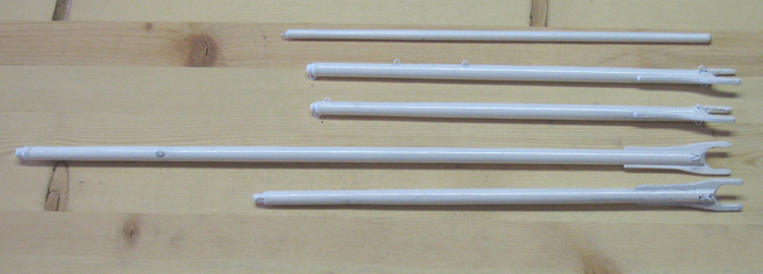
Here the sleeve is on the mast.
Looking at the deck, you can see the short mast piece inside the deck
socket.
It is flush with the top of the socket.
The mast sleeve can be seem with the marks for the top of the deck
socket.
The mast sleeve slips in to the deck socket with the mast piece slipped
inside the mast sleeve.
Deck sleeve in deck socket.
The mast piece inside the deck socket has a dab of silicone glue on
the end that will bond at the bottom of the socket.
I did this because every time I move the hull the mast piece would
fall out.
The mast sleeve is slipped in to hold the mast piece centered while
the glue cures.
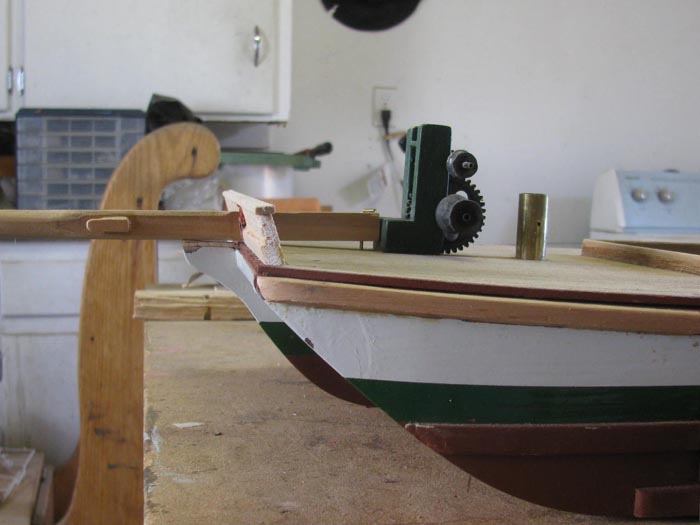
Stepping the mast.
Pushing the sleeve all the way down.
Here is the rear mast in the deck socket sitting on the short mast piece.
The lower boom is set in place for reference.
This works by slipping the sleeve up out of the deck socket allowing
the mast to slid off to the side and be laid down.
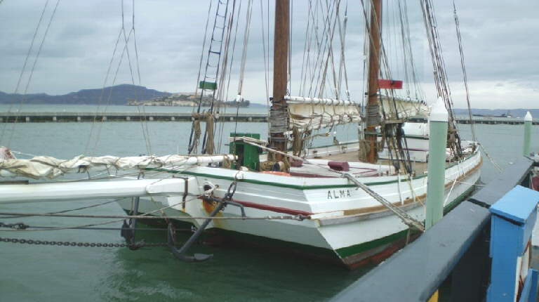
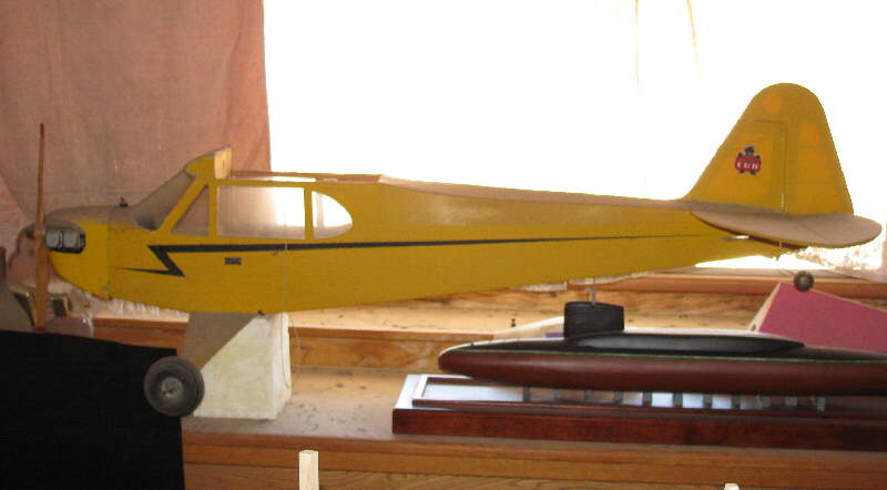
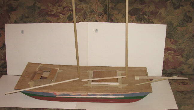
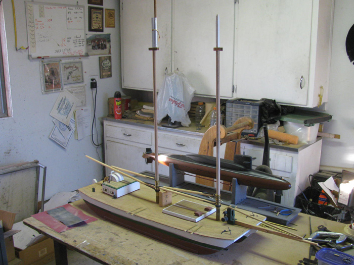
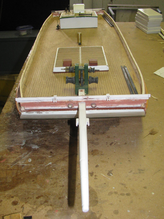
Matt Thor asked for some as is photos.
Here ya go.
My George Washington on it's stand behind the ALMA.
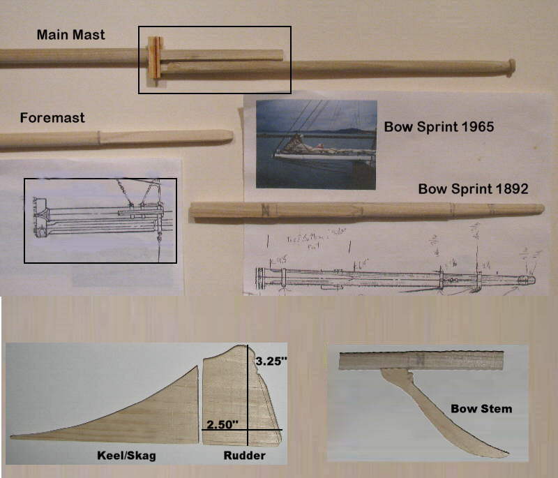
The ALMA is about the same length as the GW not including the bow spirit.
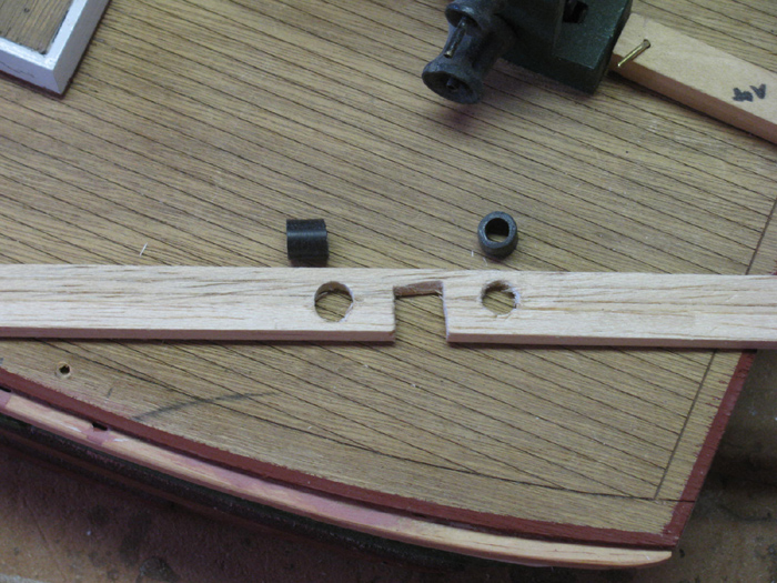
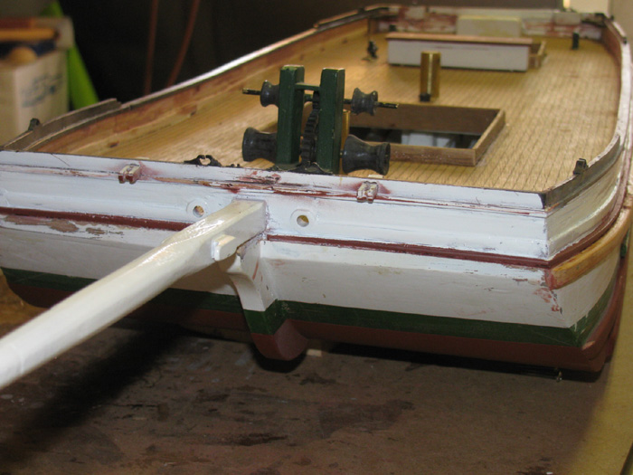
Deck Fairlead
Made from 1/2" square sheet plastic pieces.
Turned down to 7/16" top, 3/8" body and a 1/4" through hull step.
Glued in place with a backing plate under the deck.
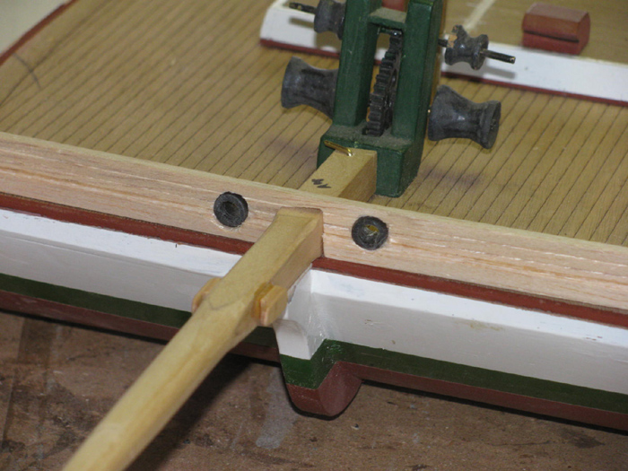
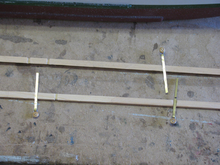
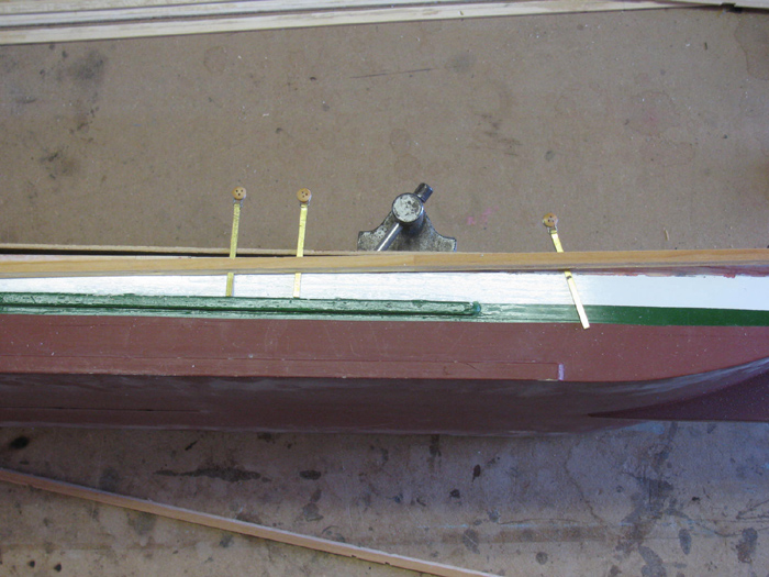
Finally decided what to do with the jib deck fairlead.
I need to clear the anchor winch with the jib boom sheets.
The real boat has a sliding boom attachment on the deck behind the
winch.
It also has a rope coming from mid way up the foremast to support the
boom.
If the boom sheet is loose, it may catch on the anchor winch if I try
to duplicate the real boat.
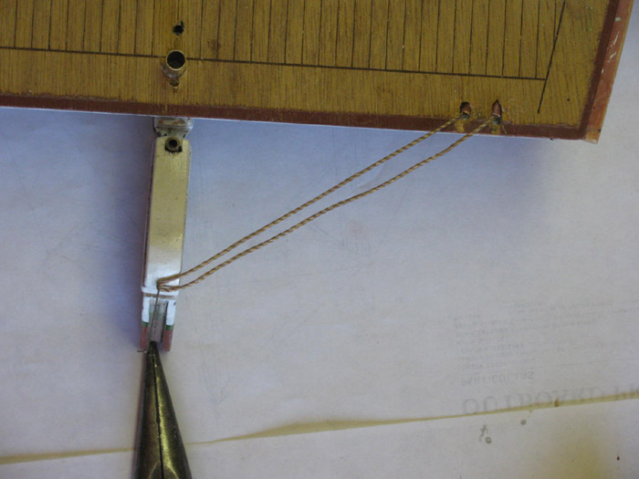
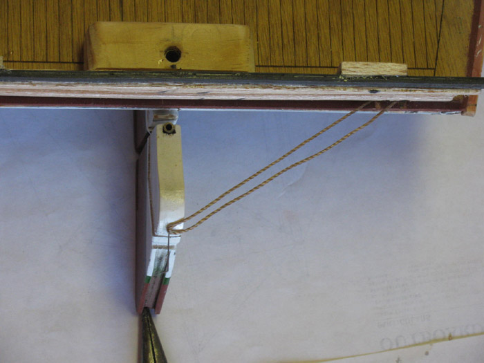
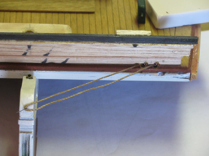
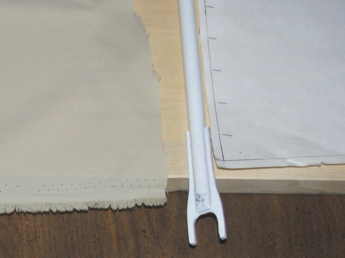
So, after a lot of thought and while working on the rework on the deck
bench, I saw a possibility.
Bring the line through the deck and up to brass eye I will install
on the most step connector up near the foresail boom stop.
This will put the jib boom sheet about 3/4" above the anchor winch
stand.
Then with the topping life, it should keep the line from catching.
May even use a small piece of elastic string under the deck to keep
a slight tension on the line so there is no slack above deck.
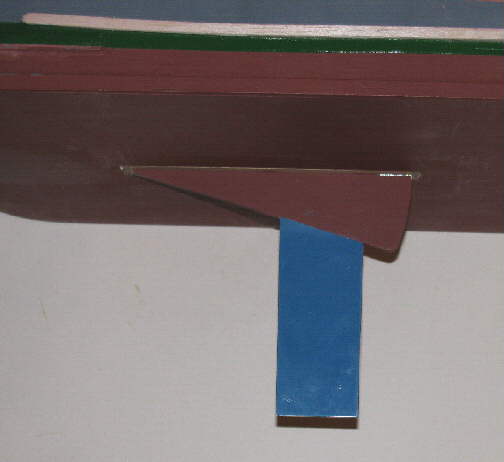
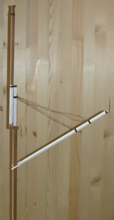
Side view.
I should mention that the line shown is not the line that will be used.
The line I will use is about half the diameter of what is shown and
it will be tripled up with three lines going through the deck.
This will make the line scale.
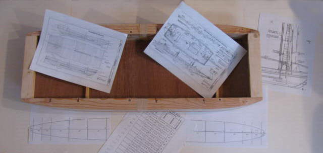
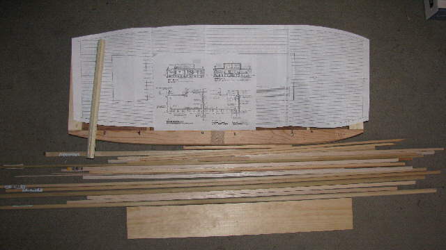
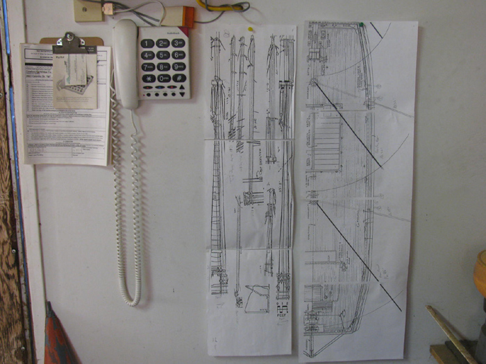
1/24 scale drawings on the shop wall to refer to as needed.
Also have lots of individual sheets of paper with various areas to
work from on the table.
I sanded the sides of the deck to fit the hull sides this morning.
------------------
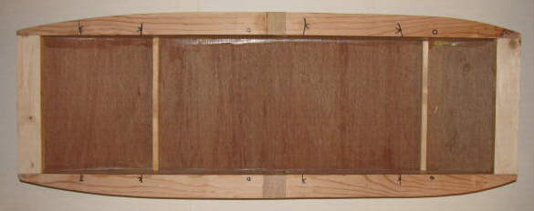
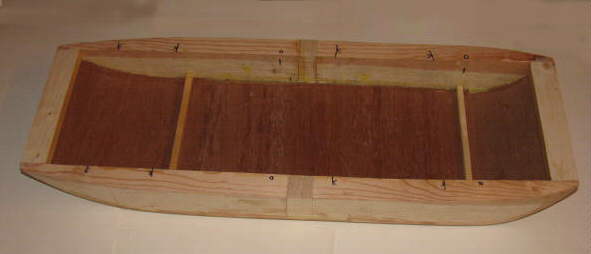
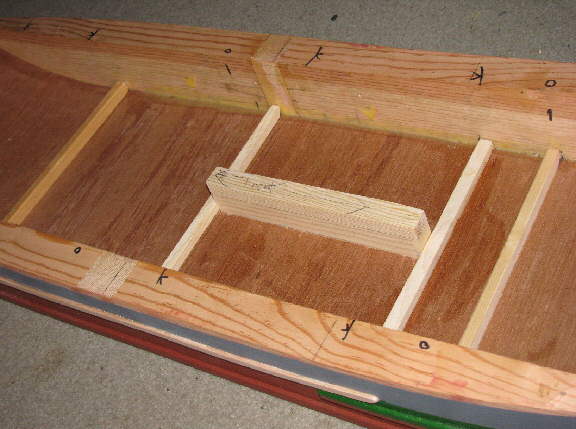
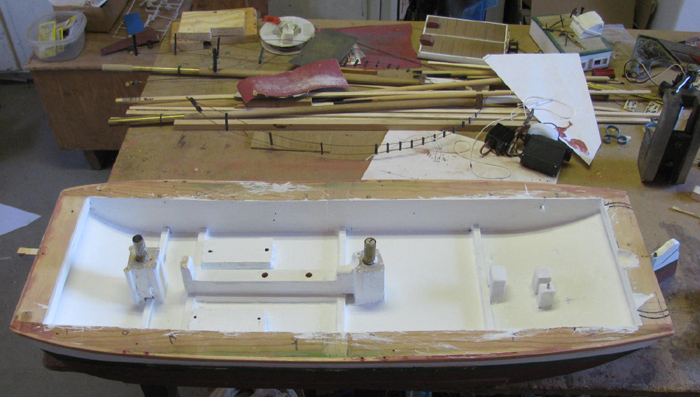
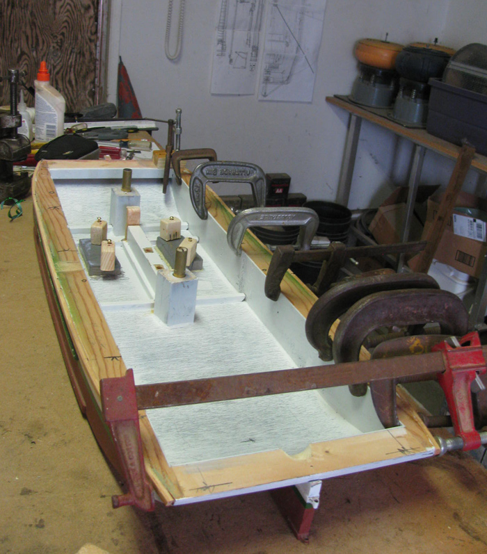
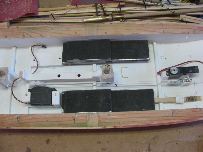
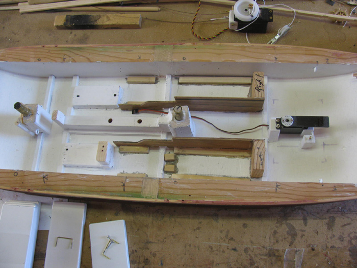
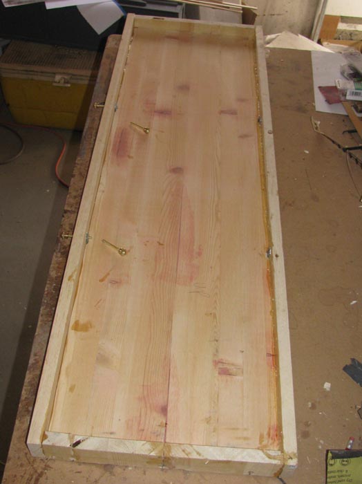
A look inside the hull.
This shows the two mast support blocks.
They are glued to the bottom of the hull.
The top of the block will be glued to the underside of the deck securing
it all from moving.
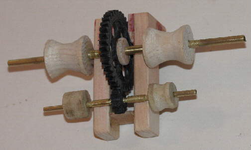
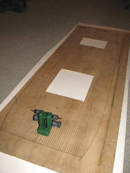
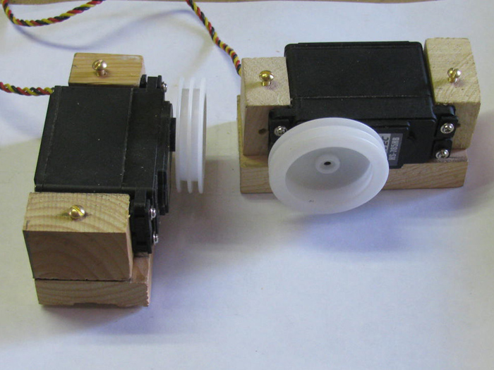
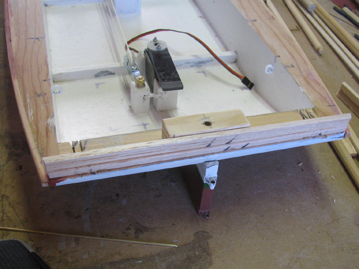
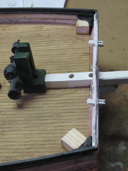
Also, in this photo, I have put some of the 3 servos and Rx to see if
they will work there.
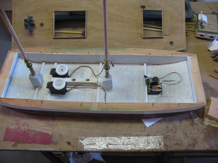
These two servos will actually be mounts with the winch pulley vertical.
As they sit, they are above the deck and will not work.
This is why they will be turned on there sides with the pulley close
to the keel trunk.
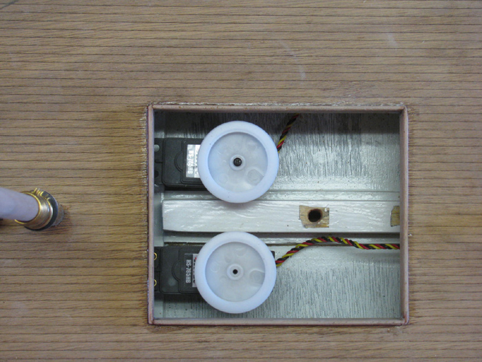
The winches will be installed with the drum vertical.
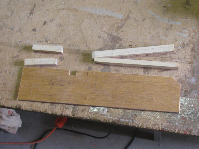
This caused and issue with putting in and removing the servos.
Solution was to make a servo mount that allowed me to remove the servos.
Two blocks that are mounted to the servo.
A base plate that will be glued to the floor of the hull.
The two servo blocks have a hole drilled vertically and the base plate
has blind nuts in the bottom of the mount.
Two brass bolts hold each servo in place which are accessible from the
hatch opening.
Remove two brass bolts and the servo with it's two mounting blocks
come out.
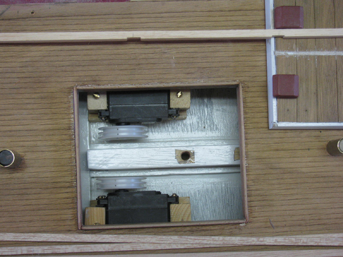
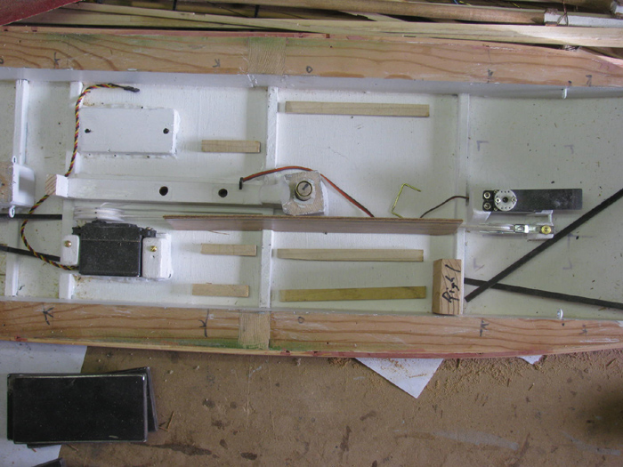
The winch servo mounts are installed.
The deck hole locations have been drilled.
The under deck wooden supports have been notched for the sail to winch
lines.
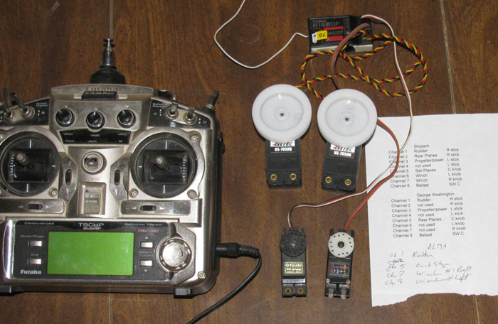
Took the Rx and all the servos in to the house and setup the system
on the kitchen table.
--------------------------
What I wanted to do was learn how to program the Tx so the channels
I picked worked the servos as I wanted.
First I made sure the servos all worked.
Did not care what channel they were on.
Once I knew they all worked, I picked the Tx controls I wanted for
each servo.
Using the Tx menu, I checked which channels the controls where on and
re arranged them to my liking.
Rudder on Right horizontal stick. (normal for me)
I wanted the sail winch servos on the Left and Right knobs.
The for the running back stay, I wanted to use the center knob but
as I played with the system, I found that it was awkward to use the center
knob.
After a moment of thinking about it, I move the back stay control to
the three way switch.
All I really need is full out right, full out left and tight on both
at center.
The Tx happens to have this three way switch.
It is the left switch above the right stick.
Switch C.
This required me to learn how to program the Tx with another model.
I did the setup but then it would ask me Yes?
But I could not find the button to push.
Then after many tries, I pushed the same select button, twice and held
it down.
That was it.
This added a new model to the list of models.
Progress
Having built servo mounts and such, I was able to calculate how much
travel was needed for the booms and rudder.
I was able to place the booms on the masts and swing them from centerline
to extreme outboard running position.
I originally thought I would need two sail winches because the main
boom needed more travel than foresail boom and jib boom.
there was also the option of making two different sized winch drums.
Well, I learned something.
Turns out that the amount of travel for each boom was within 3/4" of
each other due to the attachment locations.
this all came about by trying to make the running back stays functional.
Turned out, it really wasn't necessary.
How much full running would I do.
Not much.
After running string to the booms and down in to the hull guide eyes,
I see I ca do all booms with a single winch and a standard drum.
I had already put in the mounts for two winch servos so I can add another
later if it should be needed.
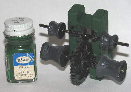
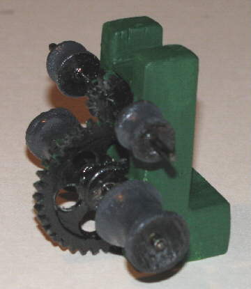
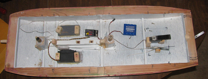
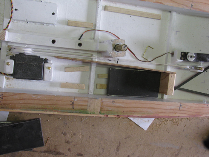
Here is a test setup on my kitchen table.
1 sail winch servo.
1 rudder servo.
1 Rx.
1 small battery pack. (which will be a 2400 later)
As you can see there is lots of room for ballast weight.
Don't know how much yet but I have to drop the hull 1.75" to get to
water line.
I need to finish the sail winch tensioning pulley mount and then I
can close up the hull.
I have all the wooden block mounts installed.
After checking the control lines in place, it is time to paint the
inside of the hull and the under side of the deck.
There will be a little sanding to clean up the areas that will be glued
together.
Not a problem because I still need to finish shaping the top rub rail.
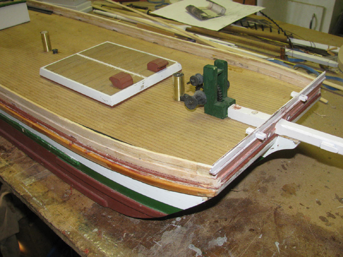
Looking at several photos, it shows the deck exposed under the railing.
The color photos show the deck that is exposed on the outside of the
hull is painted a bottom red or a reddish brown.
I do not have reddish brown but I have lots of hull bottom red. (primer)
Here I have taped off the deck ready for paint.
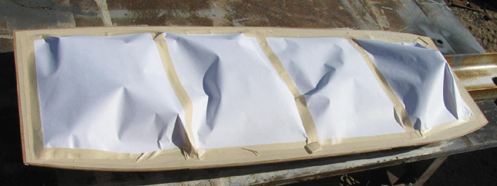
First coat.
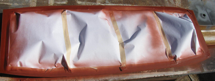
Back in the shop after 4 coats.
Bow rail sitting in place with bow sprint opening cut in.
Stern rail with rudder control pulley and lead holes in.
Finally back to working on this stuff.
Here is the stern rail with the two pulley openings and rudder control
rope eye exits.
I also made the main sail winch mule bench.
I bonded some plastic sheet scraps together and today, I was able to
shape it and then turn it i to a .400" rod with a .25" hole through it.
These will be the anchor chain guides through the railing.
Did not get photos of the turning but it was like all the other turnings
I have done.
I cut two pieces because I need to guides.
Will trim to length after I get the railing painted and before I permanently
install the guides.
Guides set in place and the bow rail set on the hull.
I can see I need to make some changed.
The guides need to be lower by half the distance.
A little file work and a little filling with balsa slivers and glue.
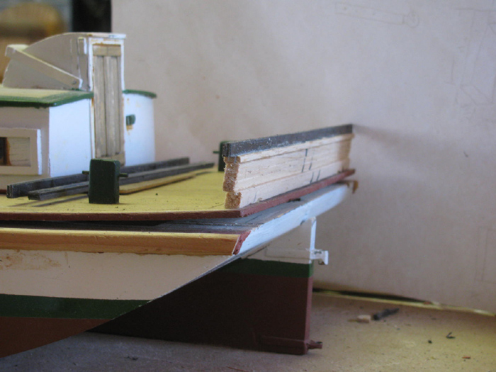
The top hand rail has been installed.
In the photo below is the stern and the top cap is the green piece
above the boat name.
I still need to make the extension above the top cap.
Stern Rail sitting in place.
Side view.
Bow Rail.
Side view.
Fitting the side rails starting at the stern
Another view.
And a view from the deck side.
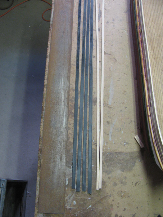
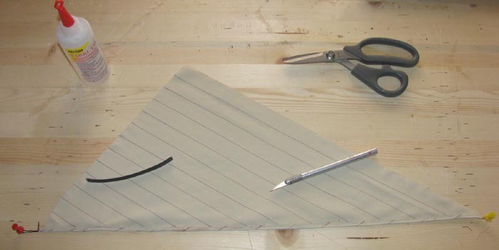
Making the top bow and stern splash rail.
I need 12 plastic strips to make the splash rails.
Here I am cutting 12 strips from sheet plastic.
Turned out that the wood strips I was going to use were too thick and
I was looking for something to use as a guide to sand the wood down to
the correct thickness.
Stacking two pieces of sheet plastic turned out to be the correct thickness,
so why not make the rails out of plastic.
Here I and making strips by dragging the back side of the Exacto knife
across the plastic using a steel ruler.
4 or 5 times and the plastic is cut all the way through.
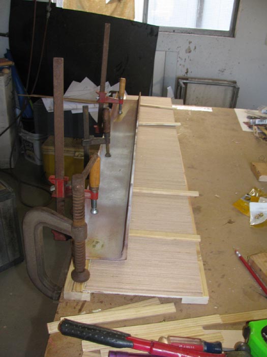
Sanded and glued strips.
Placed weight on the strips to hold in place while the glue cures.
Remember that Gorilla glue expands as it cures and must be help with
clamps or weight.
I flat sanded one side of the strips on the work bench.
Then off to the tool shed and using my drill press and a mill bit,
I slowly made the strips the correct width.
Bow = .23" and Stern = .20".
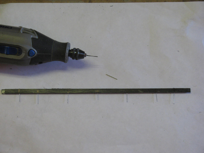
Next, I had to figure out a way to attach the plastic strips to the
wooden rails.
I have several sizes of stainless piano wire.
I cut a short length of wire and put in my Dremel.
Used it to drill holes in the plastic rail.
Rail is not quite 1/8" thick.
The photo shows the holes drilled and the short wires inserted.
Wire will be covered in glue before driving the wire in to the wooden
rail.
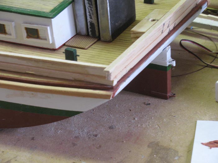
Here the Stern railing is completed and the Bow rail is ready for glued.
Stern railing set in place for a look.
A profile look of the railing.
For reference, the total railing height is 0.968".
----------------
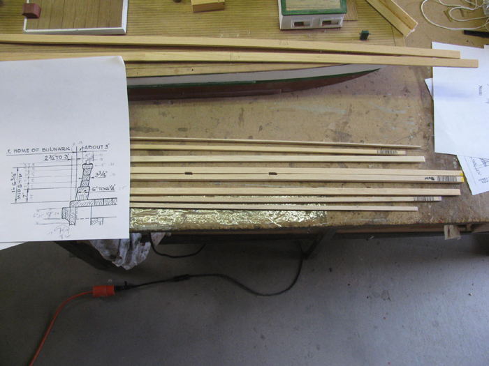
The start of the deck rails.
Here are some of the pieces I started some time ago but got set aside
because it was way too early to build them.
The draw shows what I need to build.
The lumber in the photo will build the hand rails up to the top hand
cap.
There is a small square piece that goes on the bow and stern that are
not in the photo.
They are put away so not to get broke.
1/8"x1/8" balsa is fragile.
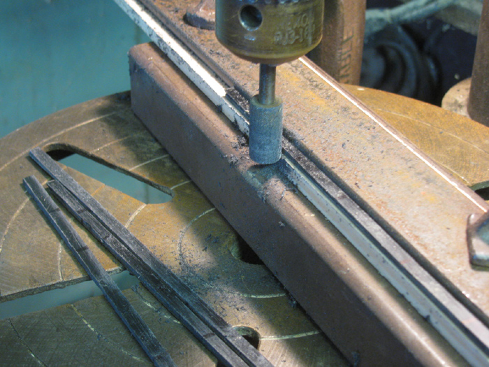
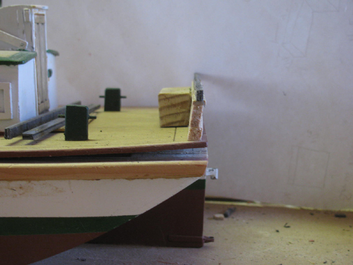
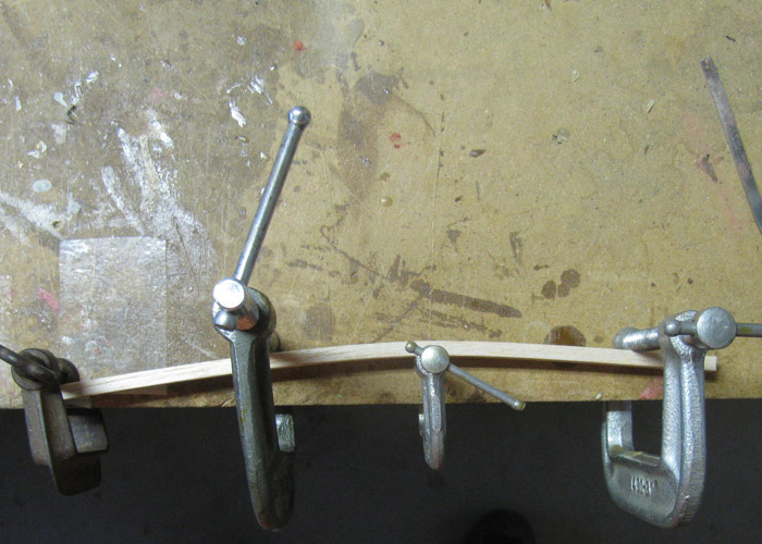
Making the Fender Rub Rails
I am making this out of a single strip of wood..
The wood strip is 33" long by .262" in height by .171 thick.
Next is to figure out how to bevel the edge.
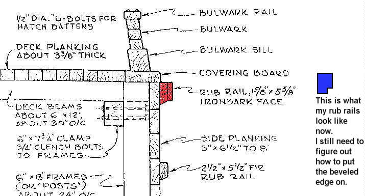
How to make the beveled edge?
I looked through my various milling bits and came up with two likely
candidates.
These are counter sink tips.
The small one is 1/4", same as the drill bit.
I did a test run of both the counter sink bits and both did not cut
the needed angle.
So I shaped and recut the 1/4" drill bit to give a flatter angle.
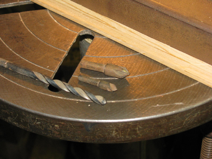
Uses a steel rectangle tube to get the table high enough to reach the
bit.
Uses a piece of steel flat as a guide fence.
Used the drill press depth control to set the drill bit down to he
shelf in the wood strip.
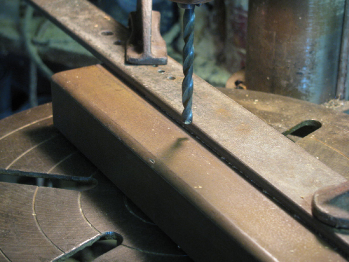
I run the wood strip back and forth about 2" to 3" at a time.
It turned out that the cut was rough going one way and then smooth
coming the other.
What was happening was the drill bit was flexing on first cut and then
straighten out on the second cut.
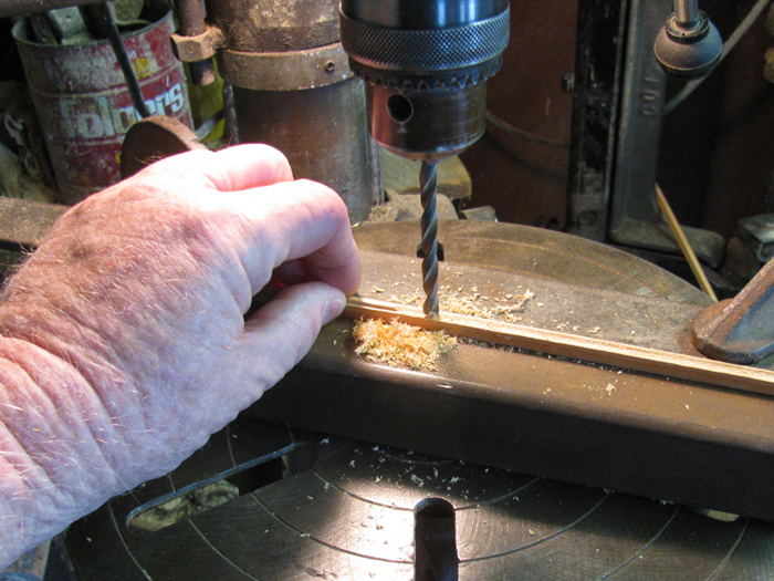
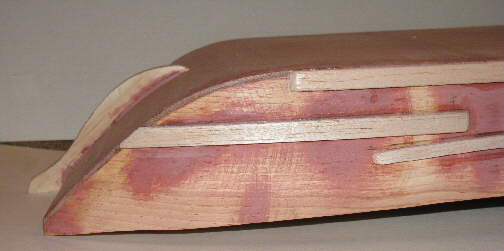
Close up view of the drill bit to the wood strip.
Right side of bit has been cut to finish.
Left side of bit is still square.
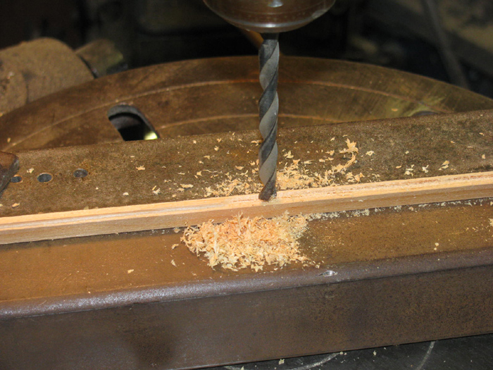
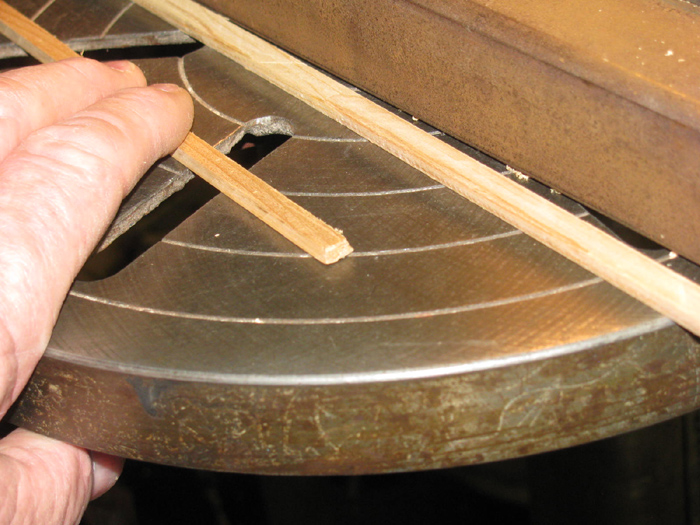
The photo was to show that the end of the strip resembles the needed
fender rub rail.
I will get a better photo when I clean up the strip with sand paper
and make a good end when I cut to length for the hull.
The sanding of the Fender Rub Rails has been completed.
Notches for the Dead Eye Straps have been filed in.
The straps go between the rub rails and the hull.
Quick look at some Dead Eye Straps sitting on the side of the hull.
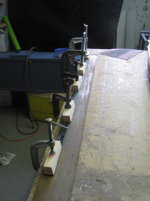
The start of gluing the Rub Rail to the hull.
I uses a 1/16"x3" steel flat bar as a guide to the top of the hull
side.
This way, I can push the rub rail up against it to make it flush with
the bottom of the deck.
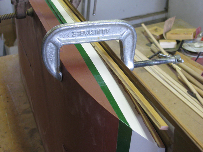
Lots of clamps and wooden blocks as wedges.
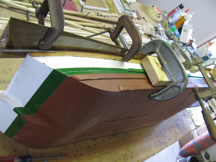
Even a screw driver as a wedge. (far left)
Still cold in the shop.
I warmed up the glue.
Got my clamps and rub rail ready.
Applied the glue and clamps.
Once I got it how I wanted it, I brought it in the house where it is
warmed and closed up the shop.
-------------------
Here is the Rx and steering servo.
Yes, an eight channel Rx.
Why?
This boat will run on 3 channels.
I need channels 5,6 &7.
Again Why.
I plan to run the sheeting and rudder from the 3 knobs on the Tx.
I do not plan to use any of the 4 sticks.
I need the controls to stay where i put them and not return to center
on their own.
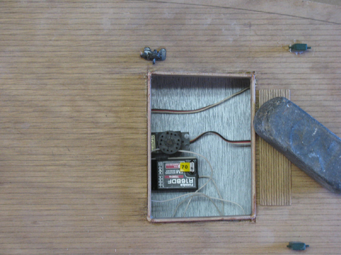
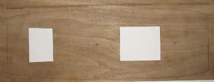
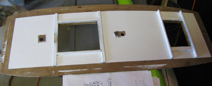
As can be seen, the hatches are very small and most of the work in the
hull will be done before the deck is permanently installed.
I need to make wooden blocks and guides to make everything work.
All the equipment has to be installed through the two hatches after
the deck is on.
So layout is very important.
There will be several lines running under the deck.
Main sheet.
Stay sail and jib sheets.
Steering cables.
And I will need to get two batteries in there.
============================
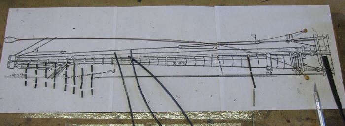
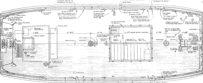
I printed out a full size drawing of the masts to see the standing
rigging.
I have cut the stay wires and I thought I would start assembling them.
After measuring the stays then the wooden steps.
I cut some sheet plastic and then ran the strips past a cutter in the
drill press and a fence to get /1/8" strips.
Then I cut them in to short pieces to match the steps on the standing
rig.
It will take two pieces to make each step.
I will file a notch in both halves to go over the stay wire.
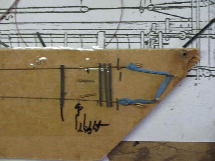
Here is a wire stay sitting on the drawing and most of the plastic
pieces for the steps.
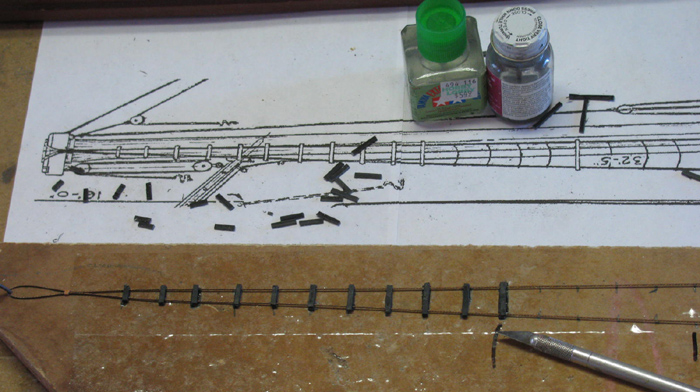
Made a board to hold the stay wires straight and tight.
Here I have mounted the top 11 steps.
Next step will be 5 steps down.
There will be rope steps in between.
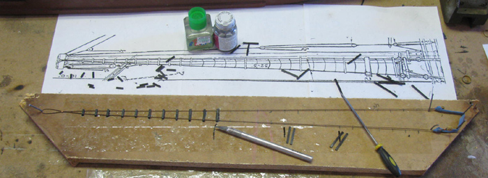
Closer view of the steps
More on the stays.
All the wooden steps are in place.
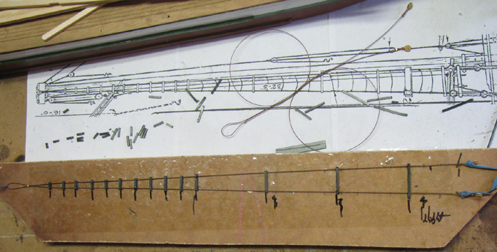
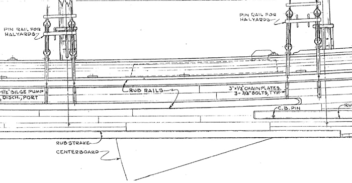
While I am working on the stays, I might as well make the stay pin rail.
Using three pieces of sheet plastic, I made these so I can put them
around the stay cable.
Once glued together, I can fill the gaps.
Each Pin Rail gets two bay lying clubs.
====================
Here is a Special Note...
The drawing of the ALMA have some incorrect information on them.
This is a good time to point out one of the items I found to be wrong.
The Pin Rails are shown in a position that is incorrect.
As shown the stay tensioners will not work.
On the drawing the Pin Rails are shown below the upper Dead Eyes which
would clamp the adjusting line so they would not move.
The Pin Rails actually go above the upper Dead Eyes.
On the drawing it shows a wooden step board above the Dead Eyes.
This is where the Pin Rails should be.
The Pin Rails will be about 5'6" above the deck.
At one time I stated making these clubs from wooden tooth picks.
Then while in the hobby store, I saw these on the wall in a package
of 25 or so.
No way I could make these for $1.79 a bag.
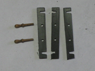
Here the three pieces are stacked with the two bay laying pins inserted.
Bad photo.
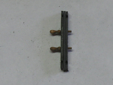
The three pieces set on the stay cables.
Here the three pieces are pushed together with the bay laying pins.
They are not glues yet.
This assembly actually goes just above the dead eye which currently
has the rubber band that is holding the stays in pace while I build.
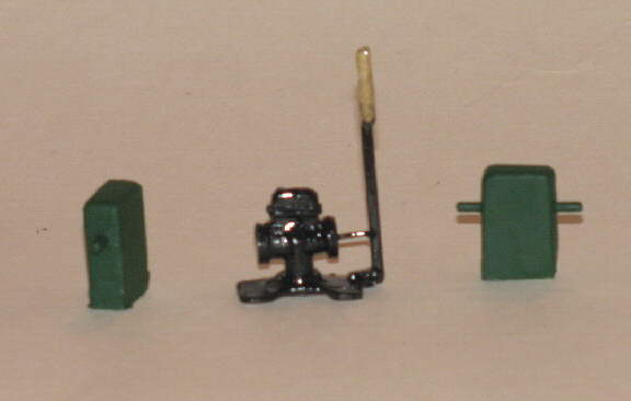
Navigation light box sitting on stays.
Better angle to see the navigation light box.
Made one for each side.
Finished the ladder on the second set of stays.
Glue curing.
Shaped the navigation light boards.
Made the two light housings.
I have painted the starboard board green and was going to paint the
port side red.
Learned something.
I have no red paint.
I have been using primer red as bottom paint for so long, I have no
real red paint.
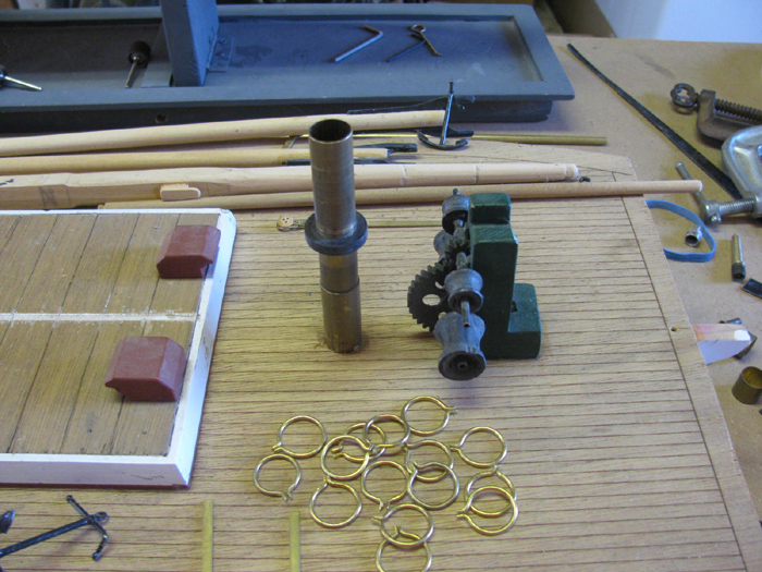
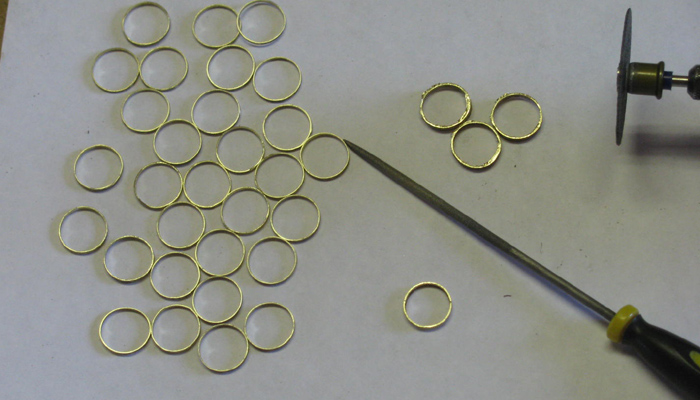
Mast/Sail rings
Making rings.
The one on the right is a cut ring 1/8" + from 9/16" diameter tubing.
The one on the left is ground finished to 3/32".
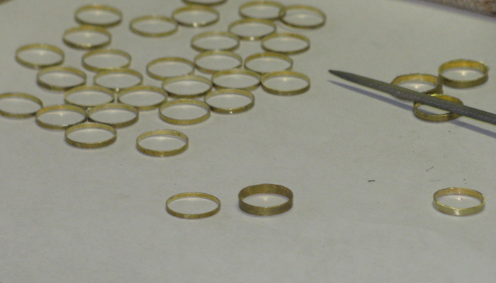
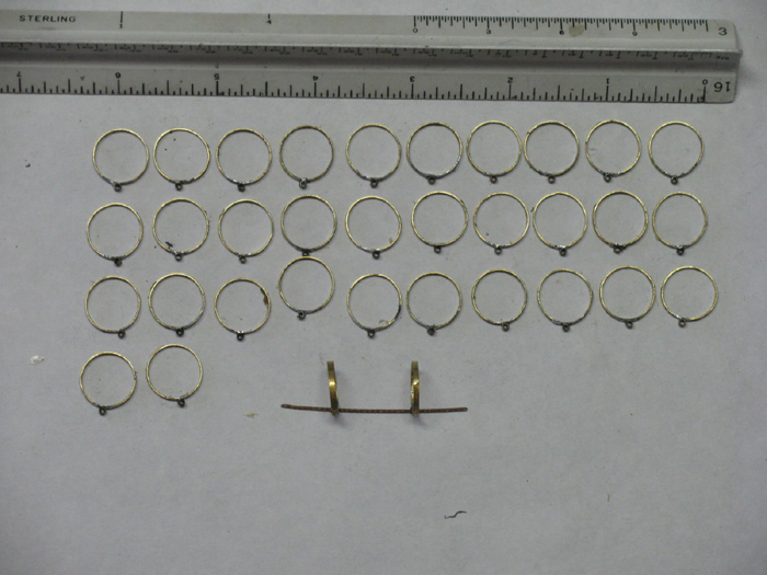
All the rings needed.
4 to go and I will be finished with these.
Here the Mast/Sail rings are completes
The sail cable eye has been soldered on the Mast/Sail Ring.
There are two rings on a piece of cable.
Ruler is for scale.
Second view.
I think I have made enough.
The count will be verified when I start assembling the sail to the
mast.
That is to come later.
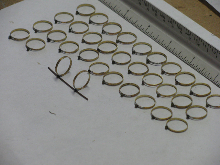
Looking at the above photo, I can see I need to inspect each ring for
solder points that need to be filed off.
I think I will be going back to the side rails.
They will give me the needed reference points to make holes in the
deck for the line leads going down to the servos.
==================
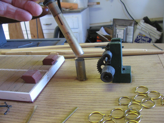
Waiting for the deck trim paint to dry, I thought I would work on the
mast step blocks.
CA the blocks on the mast connection tube.
Blocks installed and set in mast step tube to cure
Will spin the two tubes tomorrow and see if I can shape the blocks.
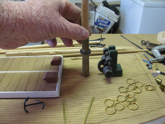
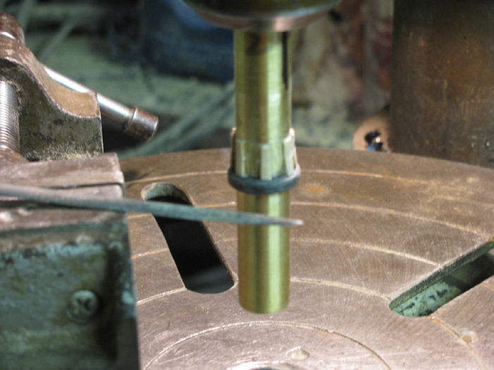
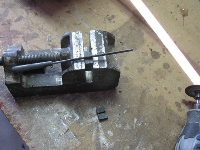
Time to shape the part.
Part in drill press and file in small vise.
Adjust height and travel of drill press.
Clamp the vise to the press table.
Slowly remove material to get to shape.
So far things are going good.
Rough shaped.
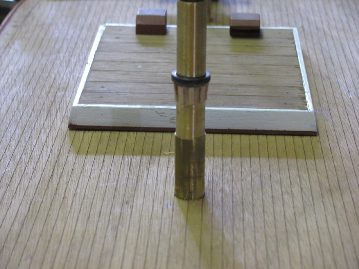
At is point it is time to use fine sand paper to smooth out the file
marks.
Looking at the part on the boat.
Little more clean up of the block edges and I think I will call it
good.
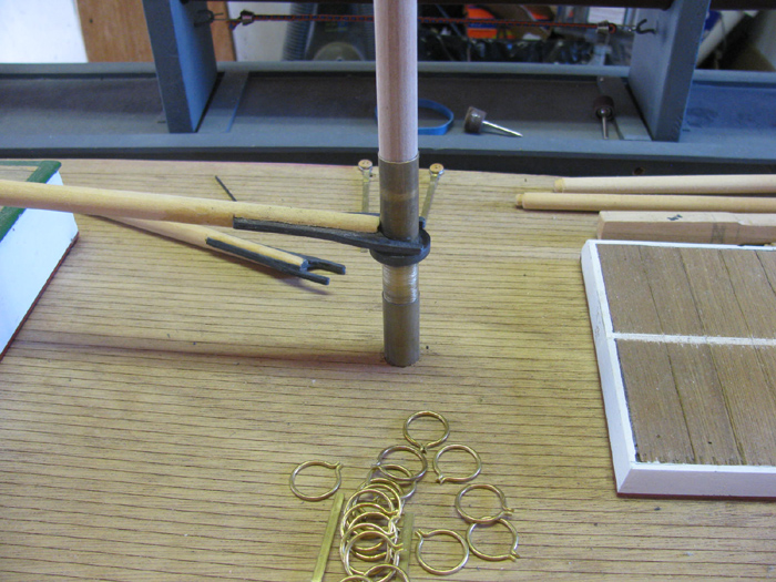
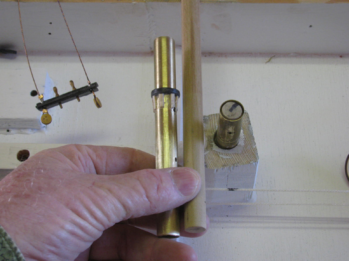
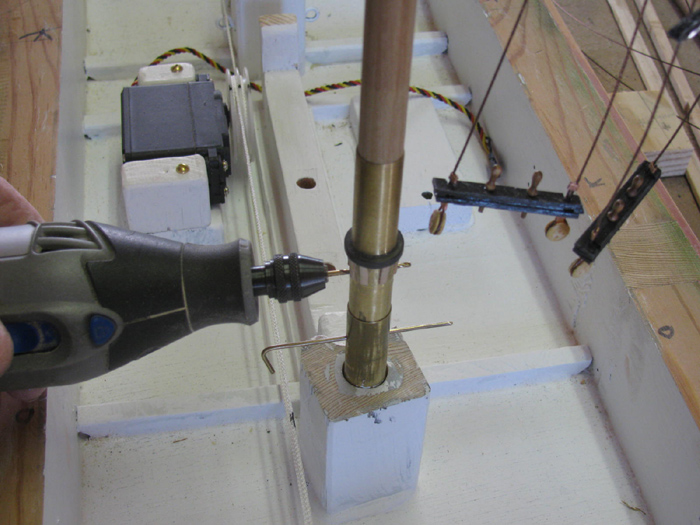
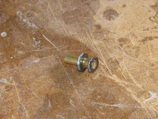
I had to come up with something to hold the mast step joiner together.
It all slips together and if I were to life the boat by the mast it
would slip apart.
Thinking a double pin would do nicely.
Here are the hull socket, mast and mast step joiner.
Drilling the lower through hole.
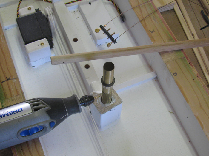
With a pin through the lower hole to keep everything straight, drilled
the upper hole.
Success.
Make the double pin.
Measure and bend.
I did grind points on the pin ends to make it easier to push though.
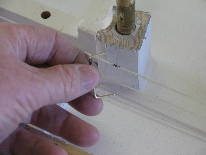
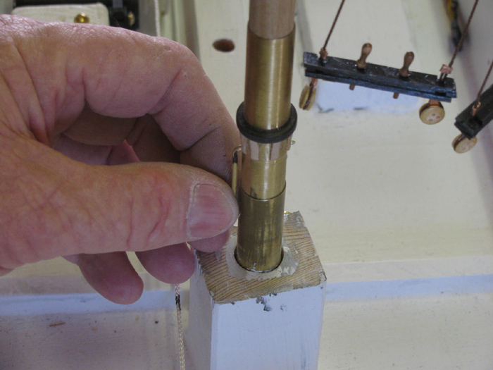
Let's see how it fits.
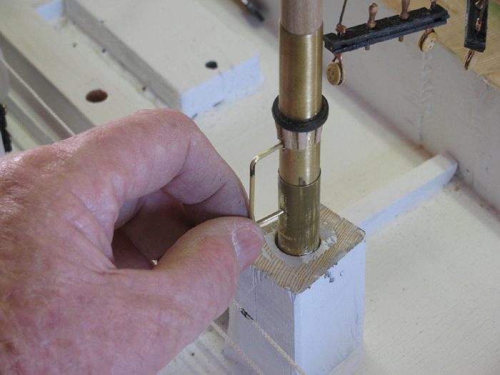
Looks good to me.
This system hold the mast to the joiner and the joiner to the hull
socket.
I can life the boat by the mast.
The pin brass is 1/16" diameter.
---------------------
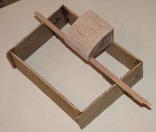
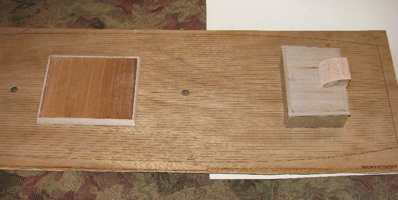
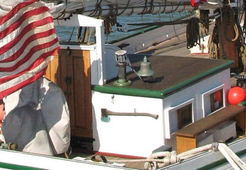
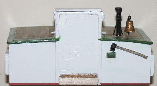
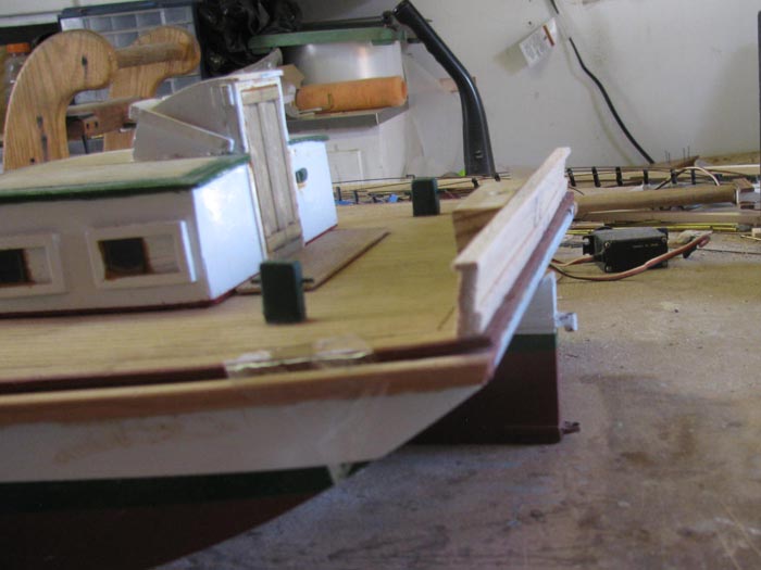
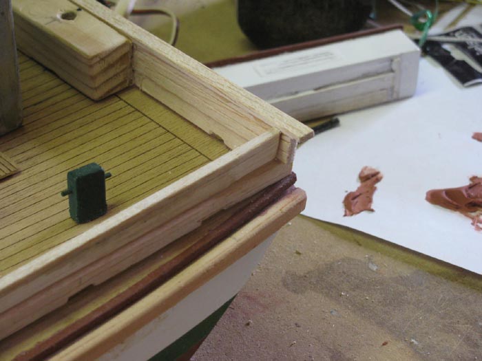
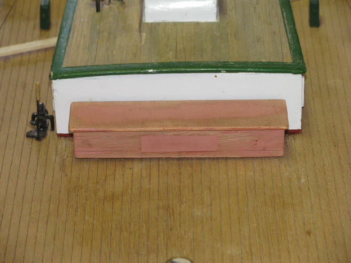
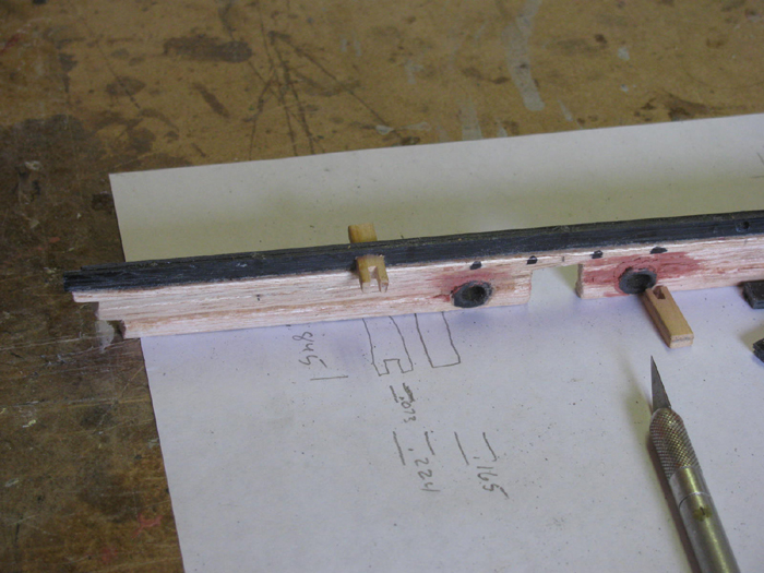
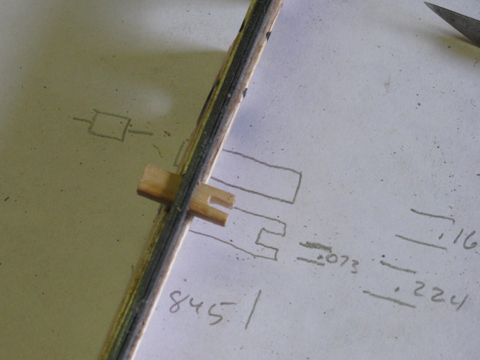
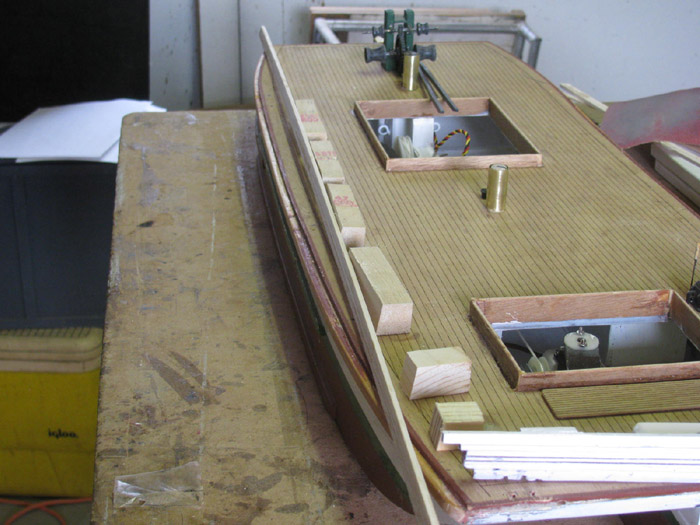
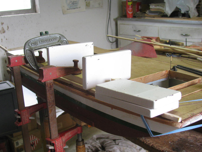
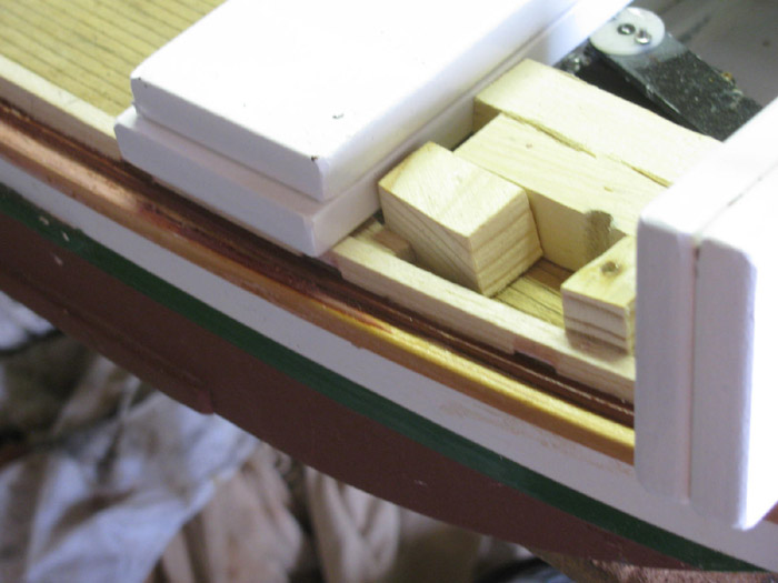
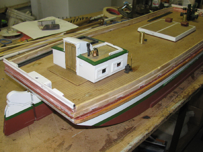
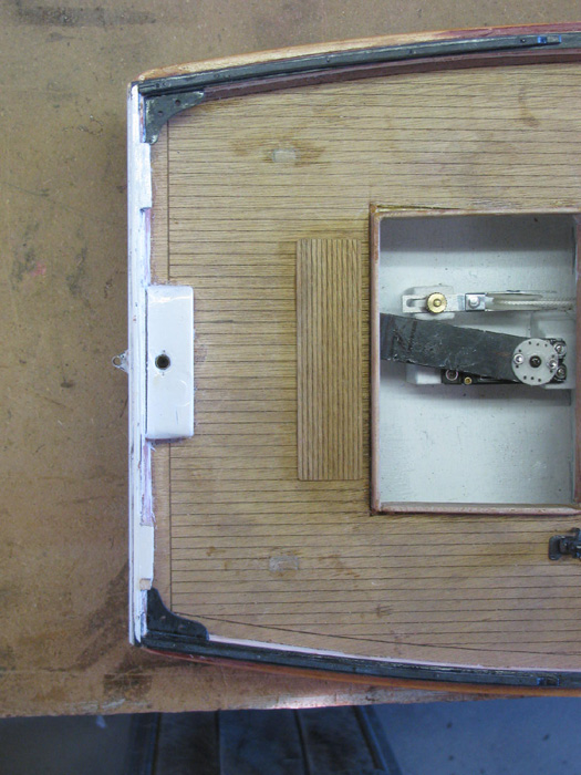
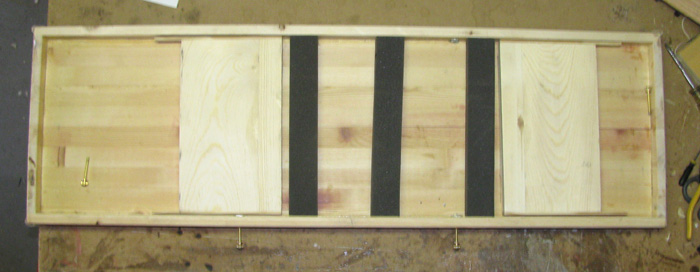
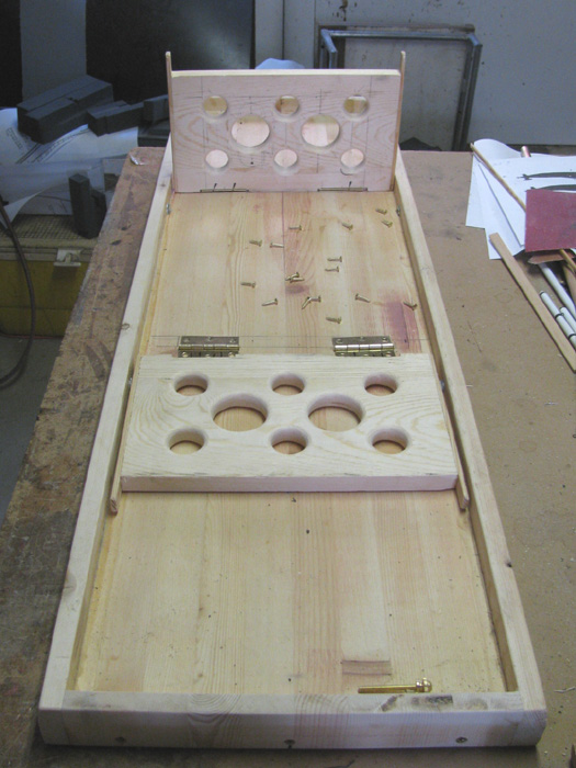
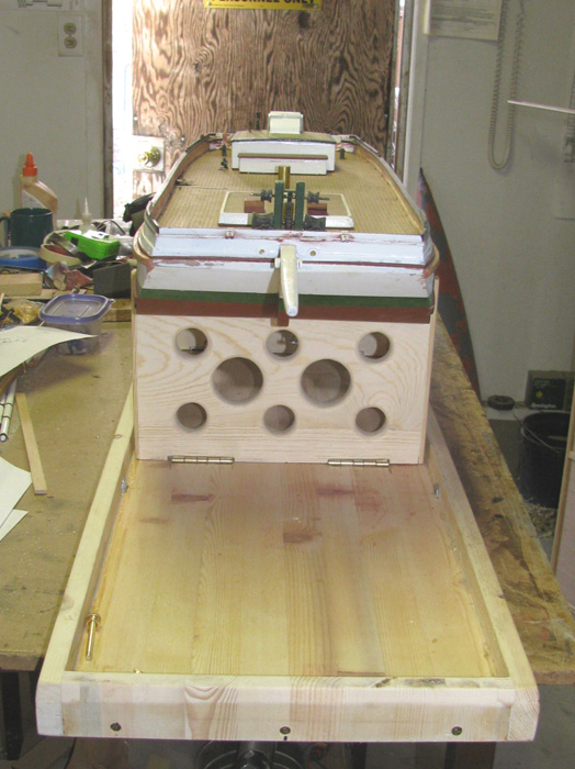
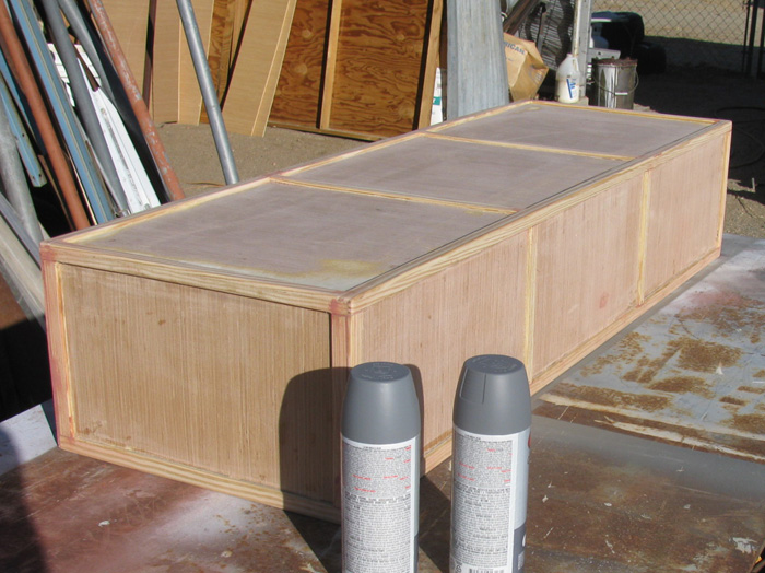
Building the deck box that sits in front of the cabin.
I will hinge the top to give access to the power switch.
This should eliminate having to open either of the two hatches once
the boat is setup ... on the bench.
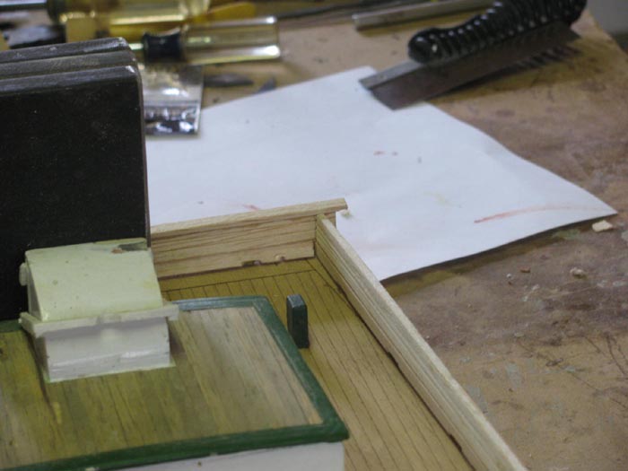
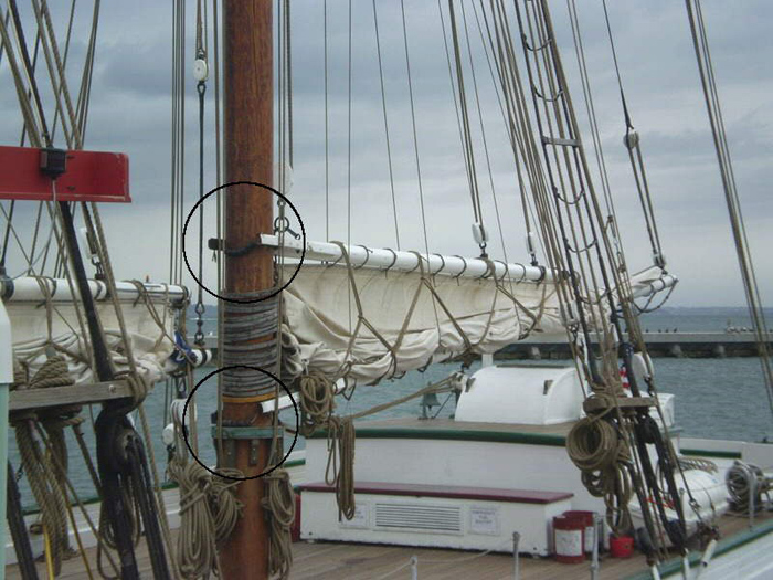
Here is the bench in front of the cabin.
Ignore the circles.
They were to look closer at the boom yoke beads.
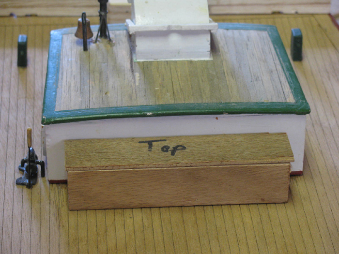
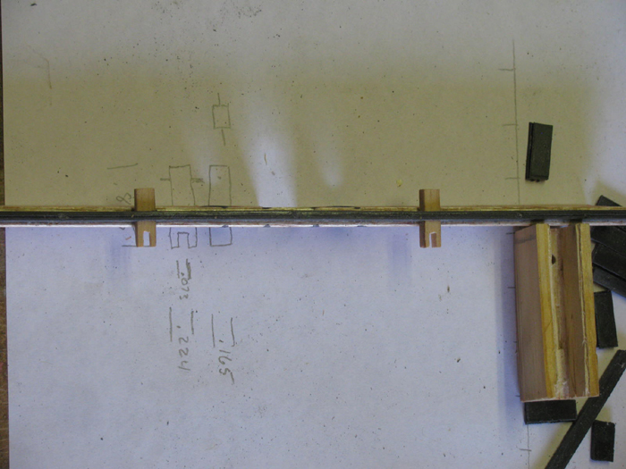
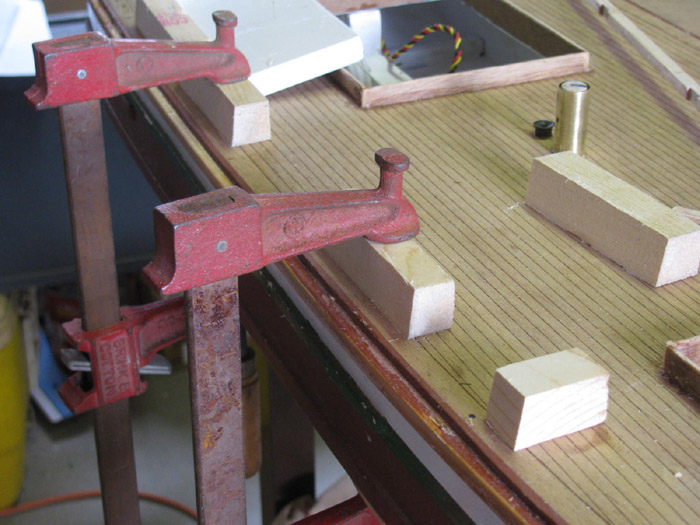
Here is the deck bench sitting in place.
Need to let the glue cure before trimming the height of the box.
I need to remove just short of 1/4".
Rain and windy.
I did the sanding and I have now brought the bench, tools and glaze
inside to warm them up.
Glazed and ready to sand.
Sanding is progressing nicely.
Sanding done.
Made inside floor piece and bottom skids.
All glued up and again waiting for it to cure.
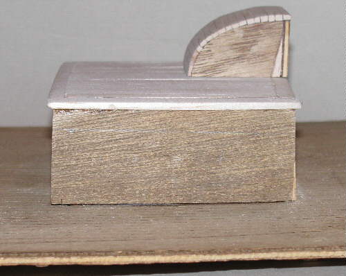
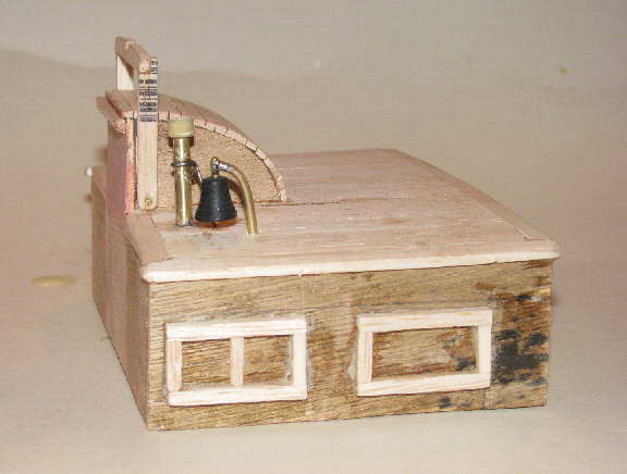
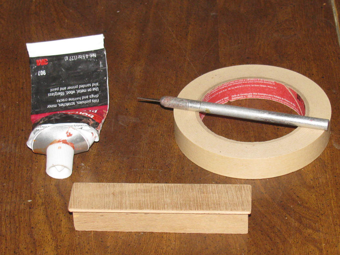
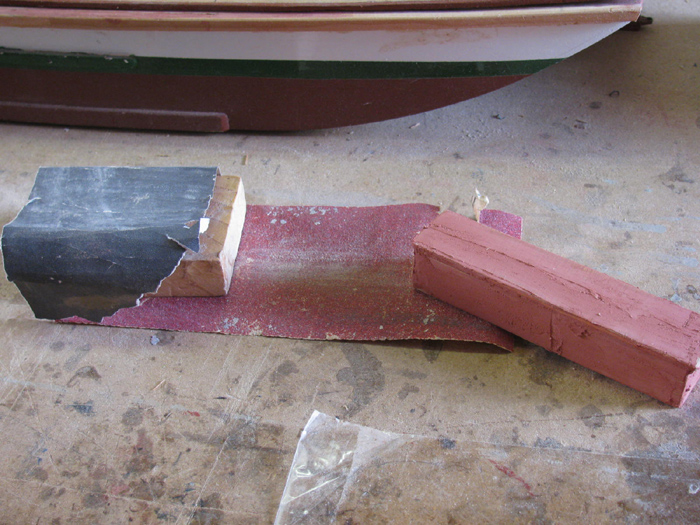
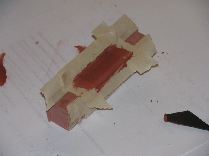
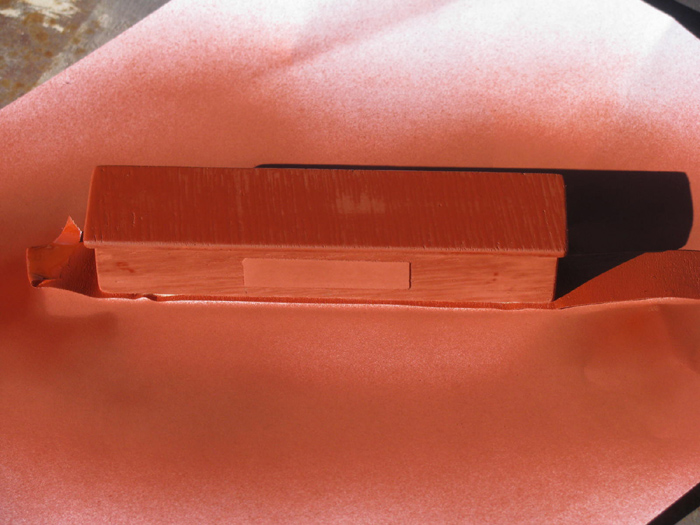
Time to put some detail on the bench.
There is a vent grate on the front side of the bench.
To build up the area so I can scribe the vent lines, I used two layers
of masking tape to make the outer frame edge.
Filled the depression with glaze.
Will let sit over night.
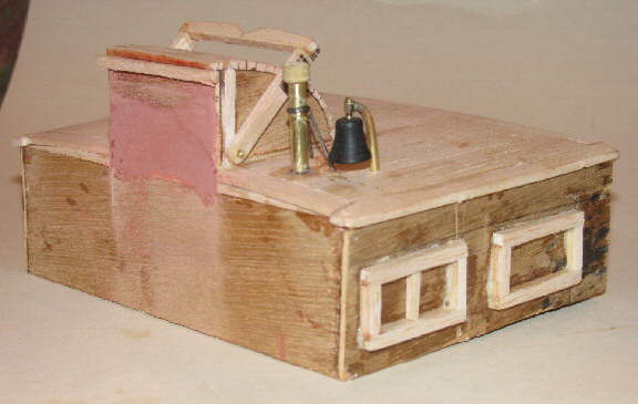
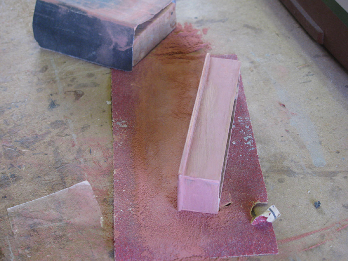
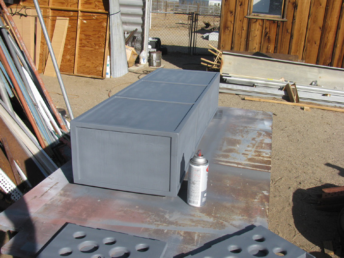
Tomorrow, I will prime the entire bench box.
After the primer dries, I will mark off the vent lines and using a
pointed scribe, I will make the vent lines.
Hopefully I will get the look I want when I apply the white paint.
Sanded the bench vent.
I do that by sanding with the tape still in place to use the tape as
the thickness guide.
Remove tape after sanding.
Then a light sanding to knock off the sharp edges of the glaze.
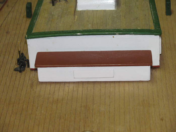
A quick look with the bench set in place.
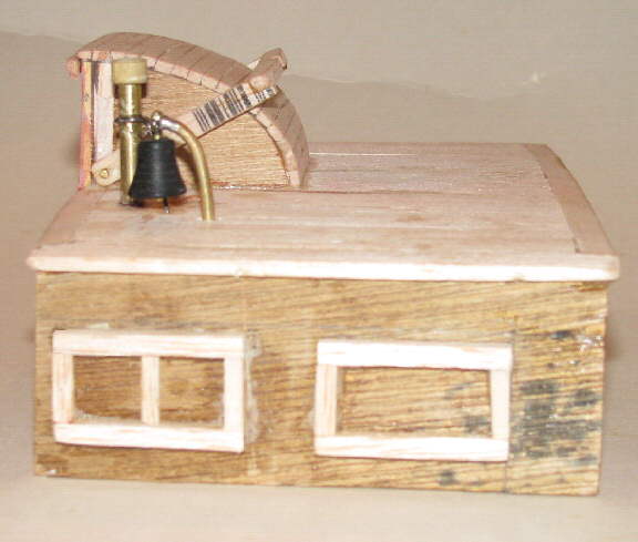
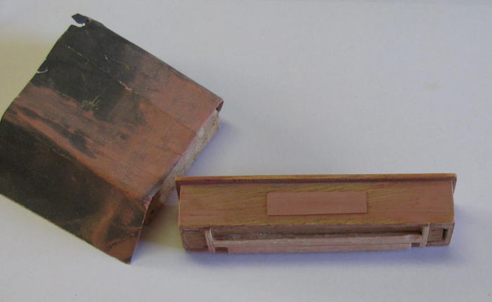
First coat of primer applied.
Should be able to get two more coats on today.
Bench is now painted.
Will let it cure for a couple of days and then I will attempt to scribe
the vent louvers.
-----------------------------------------------------
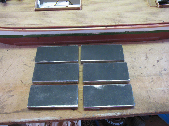
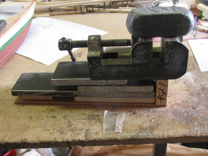
Time to start making internal ballast.
I have not done a water test to see where the waterline is, yet.
But I think I will need 10 to 15 pounds.
I did the measuring of the space where the ballast will go.
Leaves room to add more ballast if needed and it allows for movement
fore and aft to balanced the weight tot he boat.
1/2"x2 5/8" x 5" steel flat bar blocks.
In the hull.
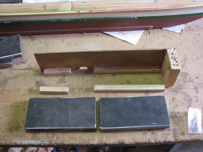
I have yet to make the frame and floor for the blocks to slide on.
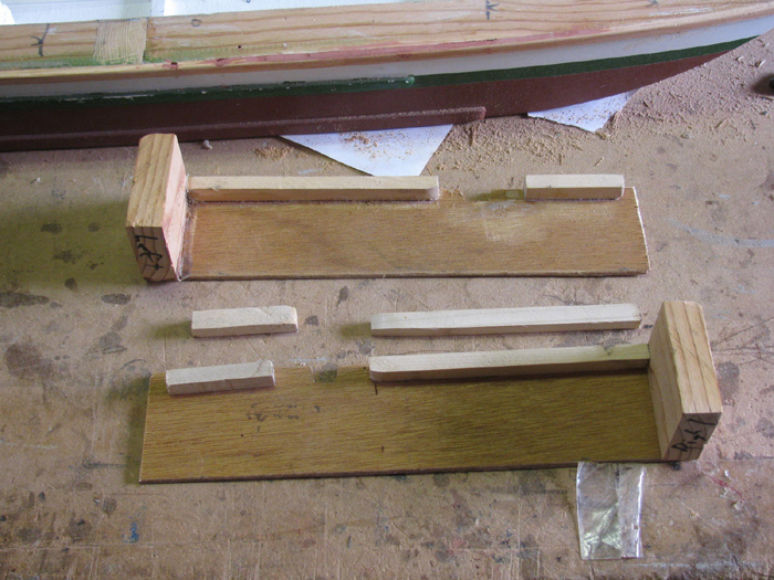
The building of ballast trays.
Each tray will have four frame pieces that will go under the tray to
support the ballast.
The hull will be one side of the tray and the other needs to
be made.
Made from 1/8" plywood panel.
Notched to go over hull beam frame and let water pass through.
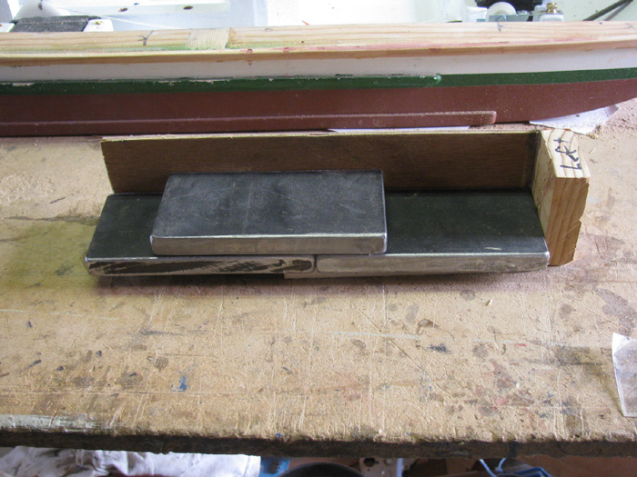
Parts set in hull
Ballast block set on pieces to find where to mark and mount tray supports.
Here the parts are assembled and being glued.
Was not able to use clamps so the next best thing is to use weight
to hold the parts while the glue cures.
Gluing completed on first tray.
Ballast blocks sitting on the tray.
Ready to assemble and glue second tray.
Glue applied.
Tray is assembled.
Placed the tray parts in the hull.
Marked where the glue needed to be applied.
Using the Dremel, I ground off the paint to bare wood.
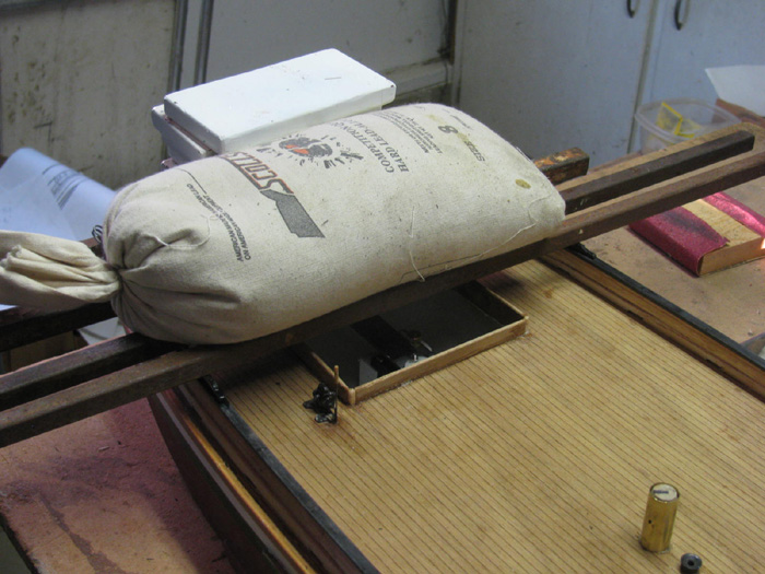
Applied the glue and using ballast blocks with a couple of wood shims
to get the needed gap so the ballast blocks would slide in and out,
I set the tray in place.
Again, using clamps is not practical.
So, weight is used.
That canvas bag is 25# of shotgun shot and three ballast blocks, there
is about 40 pounds holding the tray in place.
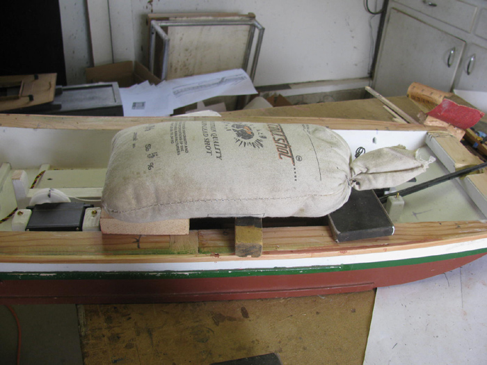
While waiting for the glue to cure (17 to 24 hours) I thought
I would prime and paint the ballast blocks.
I found other things to use as weights.
2 coats primer and three coats white.
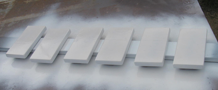
Both ballast weight trays completed and installed.
Even got the first coat of white paint on after the photo was taken.
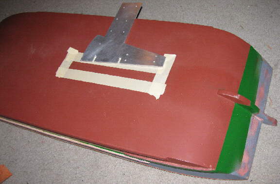
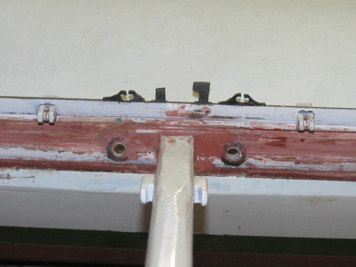
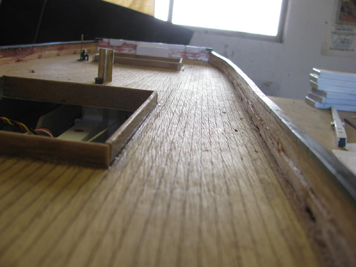
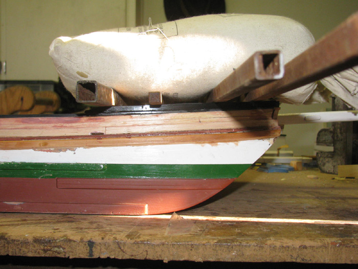
While the deck is still off, I needed to install rudder control line
guide tubes.
The lines come from the rudder and enter the boat just above the deck.
The outside line is the dead end.
It goes through a hole in the stern rail at the deck and to a cleat
on the side.
The inside guide is a pullet that turns the line to go to another pulley
on stern bit.
These two tubing guides run the lines through the deck and to a turning
eye then to the servo arm.
The eye is on the left side of photo.
There are two on each side and can not be installed until the deck
is installed permanently.
I want them to be ready to install when I get to the deck install.
There will be lots of gluing going on.
Maybe not. I might redrill the holes after the deck is on.
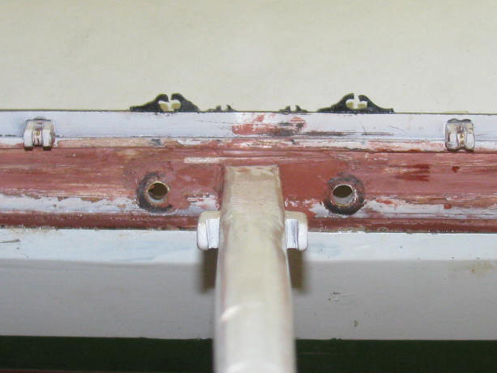
These tube guides are soft copper.
Once installed, I can run a length of wire cable through and then pull
tight to align the tube with the eye.
Tubing has been lined up.
Here is the deck sitting on the hull and the rudder control lines running
to the rudder.
The stern railing not installed.
Stern railing sitting in place looking straight down on it.
Looking at the stern rail with the right side rudder control line.
I can see I need to do a little adjusting to get the tubing to exit
more inline with the railing exit holes.
Not a problem.
I left 1/2" of the tubing end unglues so I could do just what it looks
like is needed.
Once I get everything lined up, I will glue it in place.
Besides the gluing of the stern railing will fit that.
I still need to make the hardware with two pulley blocks that go on
the top of the rudder.
Just a pin t hold the control line right now.
---------------------------------------------------
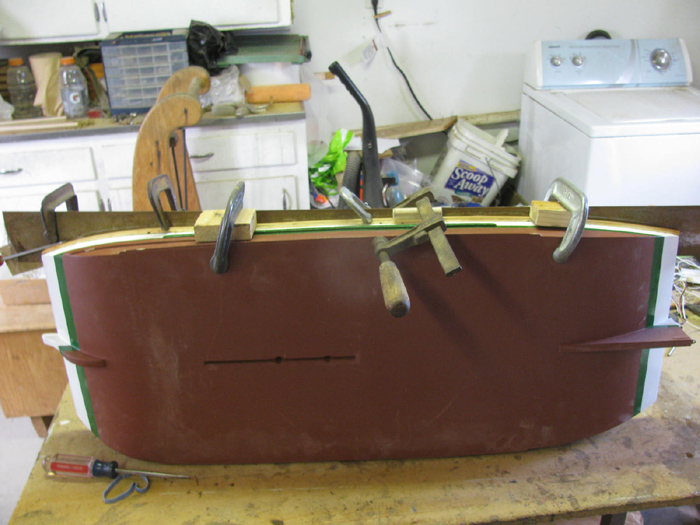
The Day Has Come !
I have put it off as long as I can.
It is time to glue the deck to the hull.
The mess of applying glue to the hull edges was done.
The deck was place on the hull.
Lining it up was not a problem because there are two mast sets and
four copper tubing coming through the deck that do not move.
Once the deck was down, I pressed it up and down to squeeze the glue
around.
There was lots of rag work to wipe the glue that was squeezed out.
To hold the deck down so it would not raise when the glue expanded.
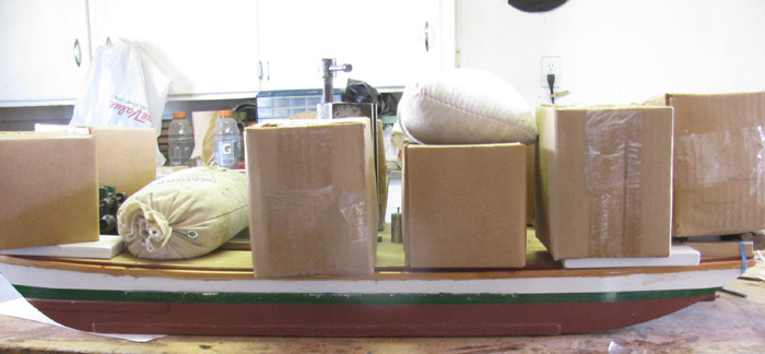
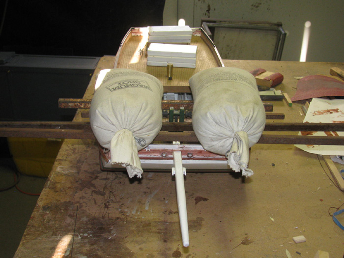
View from the top.
How much weight did I use... well.....
2 - 25# bags of shotgun shot.
6 - ballast weights at about 5# each.
and the cardboard boxes which have 200 grain 45 caliber Colt bullets.
I added it up and there is about 162.86# of bullets sitting on the
deck edges.
(5700 bullets @ 200 grains each)
Oh .. don't forget the small vise and one rubber band at the stern.
The weights where removed this morning and the glue that squeezes out
has been trimmed and files.
I can now get the Stern and bow railings ready to install permanently.
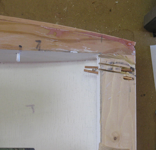
I will use .032" wire as my drill and as the pins.
The stern has a through brass tubing at the center so, I only need
one pin at each end.
This is the first pin in place .
Cut the first pin to length and then drilled for the second pin.
The pins help keep the railing straight.
It has a slight bend in it.
Did the same pinning for the bow railing but four pins instead of two.
May end up with six.
Before installing I need to get the parts primed and a couple of coats
of white paint on them.
It will make masking the hull easier later.
--------------------
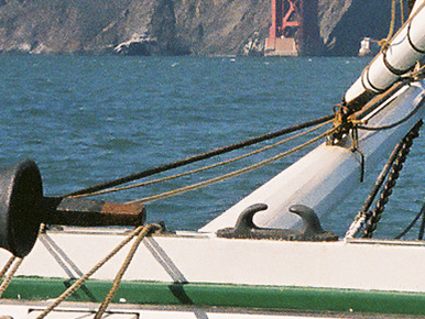
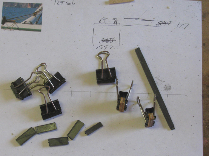
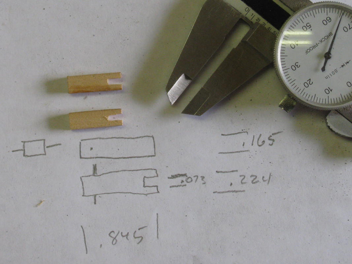
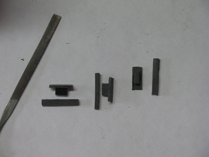
Make chocks....
The boat needs 8 of the large ones and two of the small ones.
The large ones measure 1/8" wide, 3/16" tall and 5/16" long.
???
The small ones well I think they will just be a small block of wood
with a groove filed in to it.
Cut plastic pieces for chocks and wooden pieces for cathead bits.
Start this some time ago and got side tracked.
To continue.....
Above are two pieces of sheet plastic glued together to give me the
thickness needed.
After they cured (for weeks) hum) I glued just 1/8" of each end.
I made two stacks of 8 pieces.
This will make 4 chock per stack.
I them drilled two 1/16" holes and the slowly connected them by pushing
the piece through the bit.
I ended up with two blocks with a slotted hole.
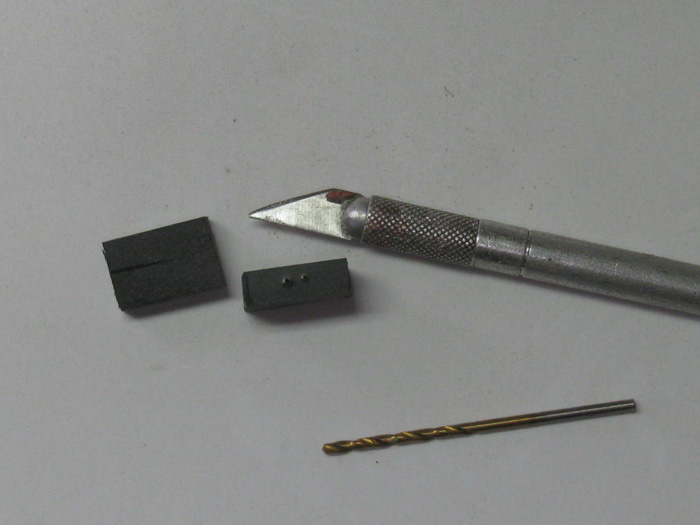
Using a razor saw I cut a slot in to the hole.
Opened up the slot with a small flat file.
With a block in the vise, I used my Dremel to shape both ends of the
block.
Side view of the the block.
After getting the top shaped, I flat sanded on a piece of sand paper
to thin the bottom of the chock.
Then the fun part, I carefully split the block in to the individual
chocks using the Exacto knife.
4 per block.
I used fine sand paper to sand the sides of each chock to get rid of
most of the burrs.
I need to clean the inside of the opening but I will wait until they
are mounted on the hull.
They are so thin, I am afraid they will break in to two parts.
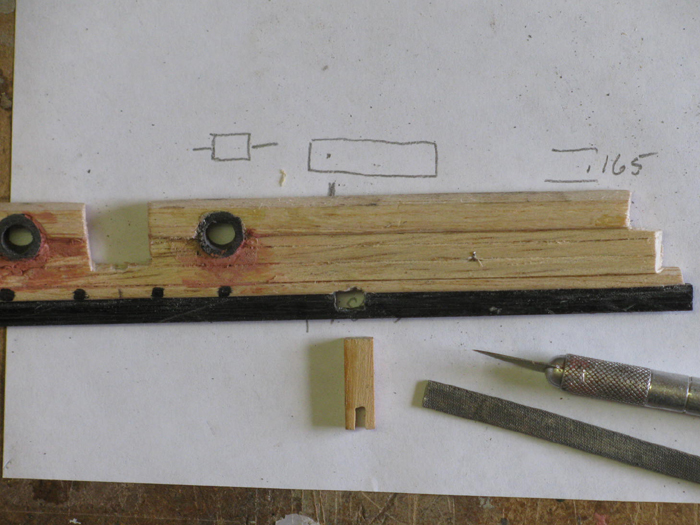
Installing the chocks on the hull.
Here are two of the six on the bow.
There are two more this size and two that are half this size.
The small ones will be made by using two pieces of sheet plastic and
gluing them to the hull with a space between them.
The ends thinned down and shaped to look like chocks. I hope!
Look at the stern.
Another look at the stern.
All four installed.
A few days ago, I put a couple of pieces of plastic scrap where the
small chock where going to be.
I made two pieces for the foot of each chock.
Size is 1/16" wide by about (guessing here) 1/64" high.
I had glued the pieces on and after curing I filed them down to the
thin 1/64".
This morning, I cut the height down and finished with a file.
Used my smallest Dremel cutting wheel and made a notch in the center.
Widened it until I could fit my small file in the notch to widen and
get depth.
For scale ..... the bow sprint is 1/2" wide.
(I can see, I need to get my magnifying glass out to do some clean
up on the other chocks)
---------------------------------------
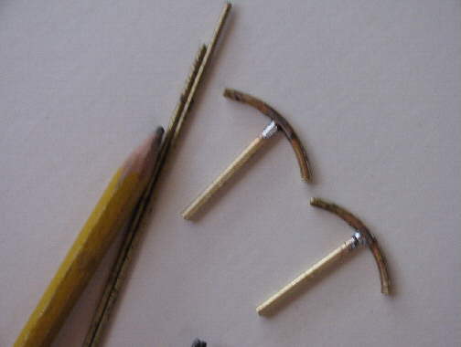
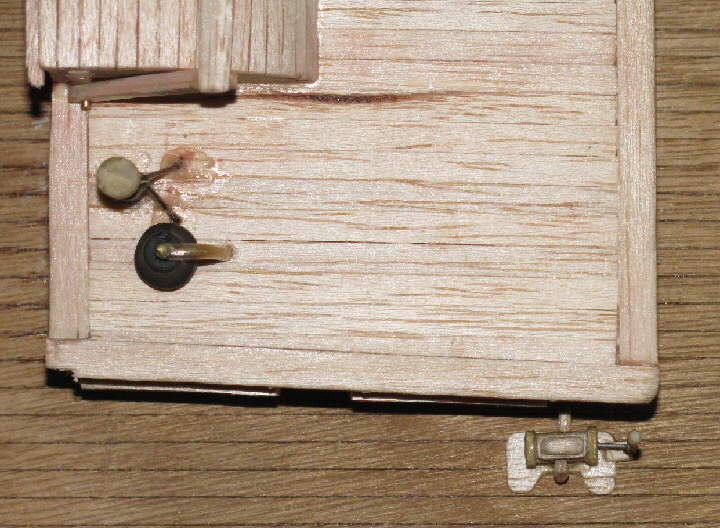
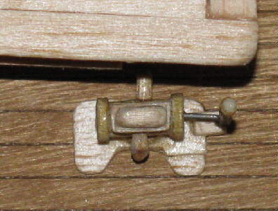
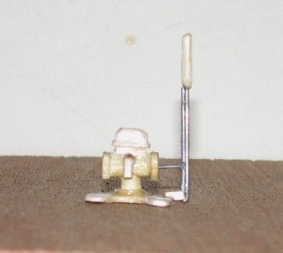
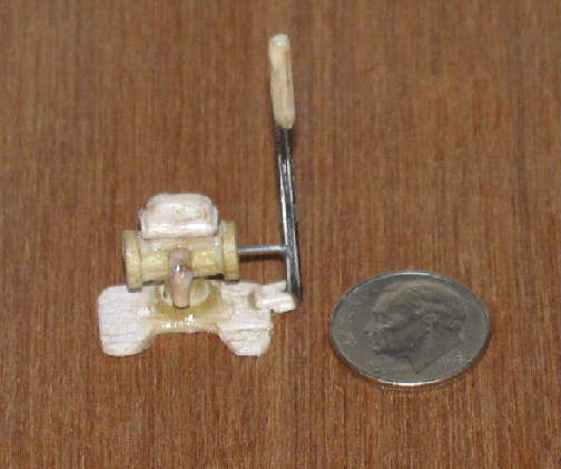
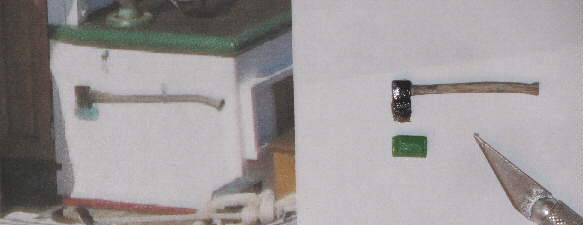
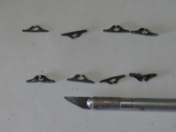
Making anchor which handle brackets.
The parts are so small, I have I have spent more time ungluing my fingers.
Here is my attempt at making the winch handle and it's mounts.
=========================
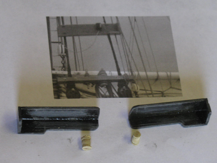
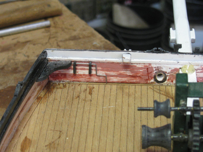
Making of the two Cathead bits.
Scaled the cathead bits and made them out of wood.
The slot is where the pulley will be.
Pulley will just be a piece of round wood for looks.
I drilled 1/8" holes in the hand rail where the bits will go through.
Using a round file to enlarge the hole length wise and the Exacto knife
to make squared off corners.
Slowly trimmed the hole until the cathead fit through very tightly.
I even found a file small enough to fit in the hole to cleanup the top
and bottom of the hole.
Here is the first bit pressed in.
A look from above.
Starting on the second one.
Both bits in place in the bow railing.
Of course a look with the rail on the hull to take a look.
Second look.
For scale, the bow sprint at the anchor winch is 1/2"by1/2" square.
Wire for bit installed
.
Brass tubing cut to represent pulley.
I made three because I dropped the first one on the floor and found
it 2 hours later.
Had already made two more.
Tubing with glue and part set in place.
Cathead bits completed.
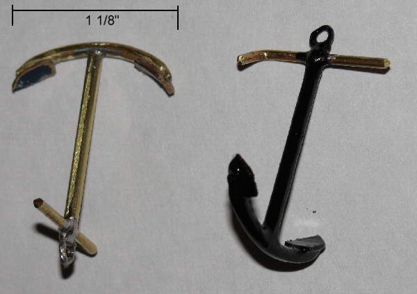
I put them in place to see how they would look doing their job.
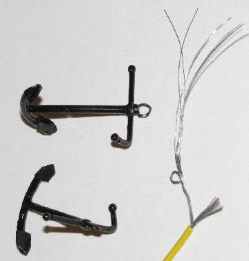
Holding the anchors up out of the water in the underway position.
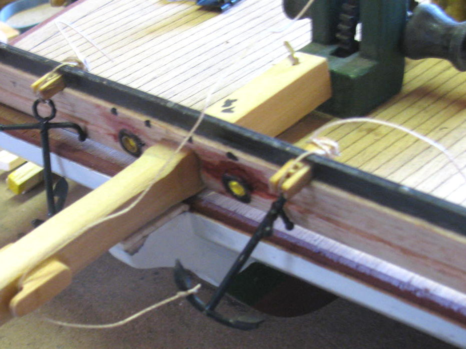
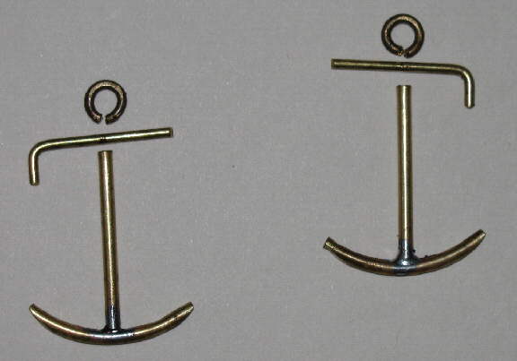
I need to find a better photo of the anchors.
With the anchors hanging on the bow, they look small to me.
I did go back tot he original museum drawing to see if I could find
something that would show the anchors.
No anchor but there is the deck storage brackets for one anchor on
the deck.
Scaling that tells me I have the distance from fluke point to fluke
point correct.
It may just be the shank shaft length is off.
If it is, it is only 1/8" to 3/32".
May not be enough to worry about.
-----------------------
While I am priming the Stern and bow rails, I thought I might as well
prime the 5 booms and bowsprint.
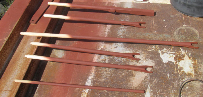
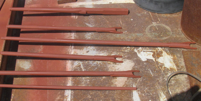
Painted the 5 booms and bow sprint.
Painted the stern and bow railings.
(Not liking what I see. Will need some more work.)
-----------------------------
While I rework the stern and bow railings, I might as well start installing
the side rails.
Got my drawing out and made several blocks with the correct angle for
the railings.
The deck is curves in both the long axis and the vertical axis.
The plan is to glue the center section that is flat and more or less
straight.
Clamping angle blocks in position so the railing board will be set
back from the deck edge properly.
The red on the deck (not the rub rail) will be exposed by 1/8".
I marked the rail where I want the glue to stop.
Applied the glue and place the rail on the deck.
Adjust the stern end to it's proper location and then hold down the
center section of the rail.
Using ballast weights (sure coming in handy) to hold the railing down.
Also some small clamps to hold the railing tight against the angle
blocks.
Even used a rubber band.
This board has the scuppers in the bottom edge.
I primed and painted those so, I wouldn't have to try painting after
installation.
The glue has not cured but after 6 hours I was able to remove the clamps.
I cleaned up the glue that squeezed out from under the railing.
I started on the section at the bow when disaster struck.
The curve was too much for the railing board and it broke. (not the
first time with this railing)
I put packing tape on the deck and matched up the ends of the board
so I knew how to put it back together.
Applied standard water proof glue, not Gorilla glue.
I set it down on the deck and using two weights and a clamp, I matched
up the ends and pushed them together.
Not a big issue.
I moved to the stern and worked on it.
The stern has less of a curve.
Besides I had broken the front part of the railing earlier in the day.
I thought I would void doing this again by using a little bit
of water on the railing to help it bend.
I slowly bend the railing as the water soaked in and weighted it and
rubber bands to help keep the curved shape.
I let it all sit for 4 hours, mostly to dry out so the glue would do
it's job.
The photo below shows the rail glued in place.
This is the part of the hull that is curved and has a 3/8" rise.
I mated the railing up to the Stern railing that is set in place temporarily.
If you look, you can see my Exacto knife sticking straight up.
Upper right corner of photo.
It is stuck in the deck holding the railing in place with tension.
Four ballast weights to hold down the rise curve
and some wooden blocks wedges against the cabin positioning frame to hold
the outward curve.
Used my fancy measuring board to make sure I had the correct railing
to outside deck edge and left it to cure.
This morning, I was able to glue the railing on the other side of the
hull.
Still have an issue with the bow section curve.
I decided to cut the bow curve section off the rail to work with it.
I can now soak the piece in hot water and then using clamps and wooden
blocks, shape the piece in to a usable curve.
I will be doing the same to the second piece after the glue cures.
Bottom side rail almost complete.
Needs short piece at bow.
Pre bending the bow piece.
This became necessary when I tried to bend it during installation and
it broke off.
Next is installing the middle section of railing.
The railing being bent and glued from the stern to the bow.
The black mark near the ballast blocks is where I stopped the glue.
After the railing glue has cured, I will use a rag and hot water to
bent the bow section in to place.
The bend is not so bad.
It's the bend and the rise that caused the other parts to break.
The front part of the railing is not on the hull, It leaves the hull
in the straight flat part of the hull (black mark)
View from rail level.
Bending and gluing the bow middle rail.
(The glue from this morning had 4 hours to bond and I can work with
that even though the glue is not cured.)
The rails are installed.
Bow and stern look.
Looking from the bow with the deck hatch and cabin sitting in place.
The four black plastic pieces sitting on the deck are the side splash
rails.
They go on top of the rail top cap which is not on yet.
Well the bow and stern are.
The cathead bits go through the bow splash rail.
Closer look of Bow.
Closer look of Stern.
I had about 45 minutes this morning before leaving for the day.
I went out to the shop and thought I would make sure I had enough wood
pieces to make the railing cap.
I did.
I set one cap on the rail to look at it.
I then had a thought about the wooden cap.
It is balsa wood and very soft and will ding easily and show damage.
Sitting on the deck were the plastic splash rails.
I set that on the radio see if it would bend to the curve of the hull.
It did.
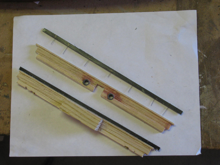
The thought was could I use the plastic to make the rail caps giving
the rail some protection from dings and other damage.
To do this, I would need two layers of plastic sheet 1/4" wide and
33" long.
I can do that.
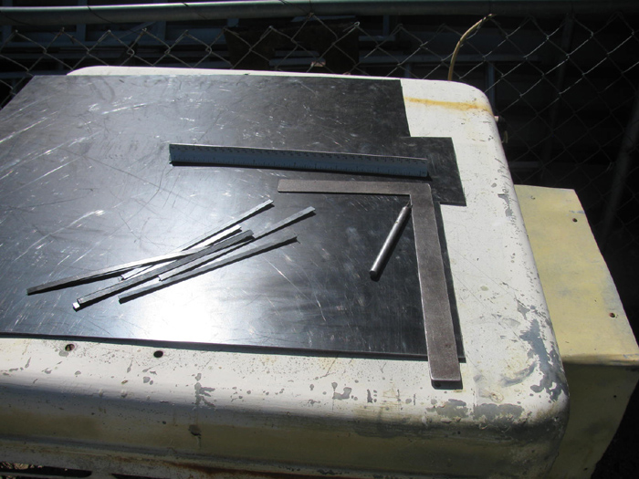
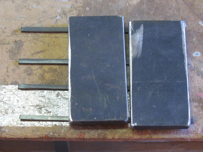
Got my big sheet of plastic on the steel work table outside and started
marking and cutting (with the back side of the Exacto knife) 3/8" strips.
I would need to bond two pieces together to get the thickness needed
to make one cap.
Left photo shows the strips and the wooden pieces. Right photo shows
the plastic strips clamped after applying the cement.
Next time in the shop, I will use my drill press and a mill bit to
make sure one side is flat and straight.
Won't take much because I did some flat sanding before bonding to get
close to flat and straight.
Then I will set the mill to make a 5/16" wide cut of the strips.
Then making very small passes, I will sneak up on the 1/4". Actually
.246" to be scale.
The top caps are made and the installation begins.
Using wire pins and glue, I started at the Stern rail and worked foreword.
Weighted all down and then started the other side rail cap.
The glue has cured.
There is trimming and clean up to do but here's a close look from deck
level.
Lot of fine sanding in my future.
But while looking at this close up view, the consider that the deck
boards are less than 1/4" wide and so is the top cap.
Most of the imperfections will disappear after priming and paints.
(when I get there)
I will do cleanup because I know how it looks now.
Time to install the bow sprint permanently.
The bow sprint is glued and held in place with two screws down through
the deck in to wooden blocks under the deck.
While I am at it, might as well install the bow railing.
Glue applied and part set in place.
Weight added on top of railing and there are blocks behind the rail
to hold the angle.
Installing the Stern Splash side rail.
Drilled holes through rail and top cap for .020" wire pins.
Put pins in which required a bit of hammering with a small hammer.
Turned the hull on it's side and applied thin plastic cement to both
rails.
Let it run under the rail until I could see it on the other side of
the rail.
Then turned the hull over and applied the plastic cement again and looked
for it to run thorough.
Turned the hull upright and place the steel tubing pieces across the
rails.
Set the weights in place.
Looks to be about 55 to 60 pounds. (6 ballast weights, 25# of shotgun
and the steel tubing.
Sat over night.
Removed the weights and tubing.
Place the cabin on for a look.
Next, I did the same to the bow splash railings.
Drill, pin, cement, steel tubing and weight.
Will let sit for a few hours.
A look at deck level at the tubing holding the weights.
Weights removed.
Some sanding to clean the top of the splash rail.
Moving on to the corner knees.
Need one for each corner of the hull and hs two belaying pins each.
First attempt was out of wood.
Realized that I had read my scaling incorrectly and the wood was not
going to work.
What to do?
Plastic, of course.
Made the stern parts out two layers of sheet plastic and shaped them
to fit.
Here they are after they have been glued in.
Here are the bow knees glued in.
I made wooden support blocks to hold the knees at the correct weight
while the glue cures.
=========================
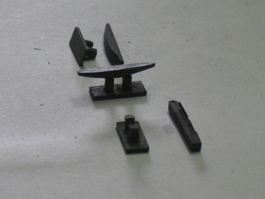
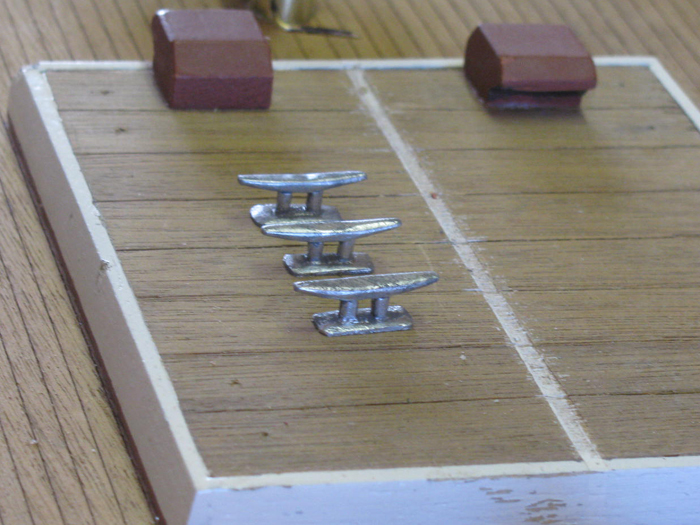
I need 3 - 24" cleats.
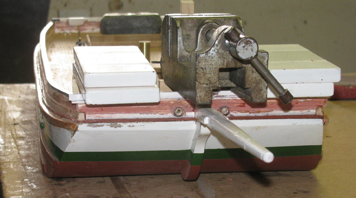
I have found 16" metal & wood cleats but nothing near 24".
So, I will attempt to make them.
Starts by cutting pieces from plastic sheet.

Three bases made.
A little over size for final shaping.
Taking a look.
Base and top of cleat sitting on the bow sprint.
Cut the cleat base stand to height.
Shaped first cleat top.
Sitting in place for a look.
The top of the cleat will be shaped after the pieces are bonded and
cured.
3 cleats assembled and cemented.
Final shaping to come..
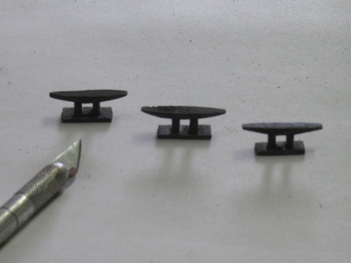
The cement has hardened enough to do some more shaping.
Put the curve in the top of the cleat.
The bond is still soft so I will wait to finish shaping the top of
the cleat to it's round shape.
Here is the cleat on the bow sprint again.
It will be located mid way between the bow railing and the anchor winch
when I install it permanently.
I am glazing all the little dents and nicks as I find them.
On the bow sprint it was two screw holes.
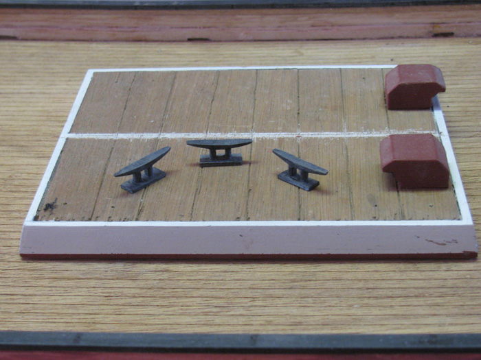
I placed a cleat in the foresail sheet location.
Finished the filing and sanding.
Now for a little gray and silver paint.
====================
Again I was trying to come up with something that would work as a standing
rig disconnect.
Two more failures. (in to parts box)
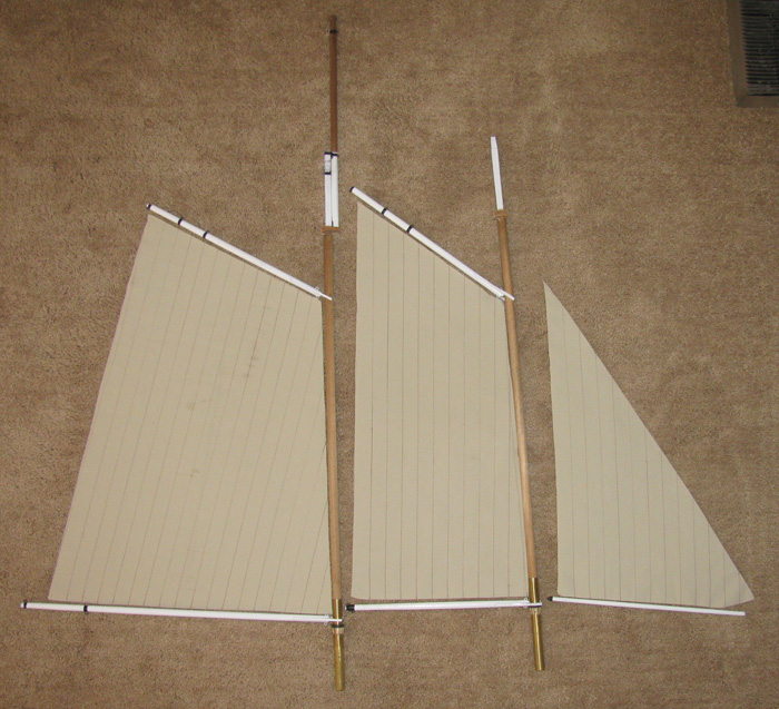
I decided to stand the masts and see how they would come down with the
stays in place.
It became so obvious that the stays are not an issue to take the masts
down and lay them on the deck for transport.
The tallest masts is shorter than the hull, rudder and bowsprint.
On to next issue.
The booms.
With the booms attached to the masts, they do not fold up against the
masts so the width is the problem.
I am at making the boom chokers disconnect on one end.
This will allow the booms to be moved how ever they need to be.
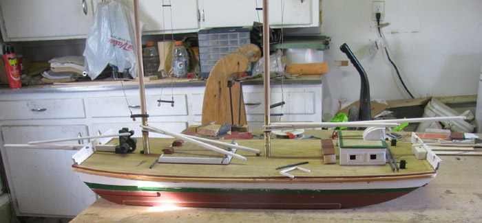
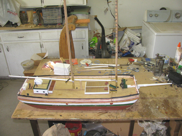
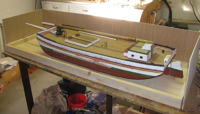
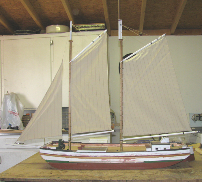
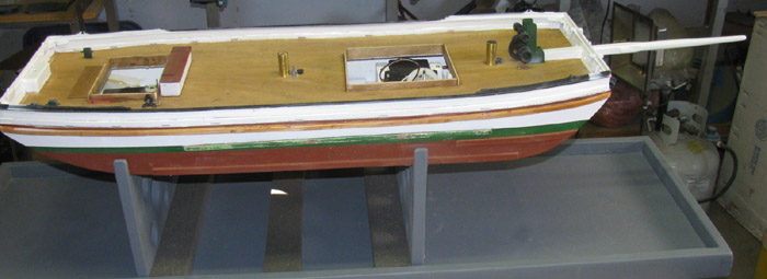
While I had the masts standing and some of the standing rig on the mast,
I thought I would take a photo of the ALMA to show the progress.
All the building posts are not in any sort of order so it can be hard
to follow what has happened.
Currently glazing spots on the hull.
Working on standing rigging.
Installing small deck parts.
Looking at where I am and what I need to do, I think it is time to clean
of the bench and put useable parts in a box and
trash all the unusable plastic, wood and brass cutoffs and trimmed
pieces.
I have tools from the tool shed that I will most likely not use again.
Example would be the small vise.
I think I can out that way.
Clean up?
Yes, I need room to put a submarine on the bench to trouble shoot the
main motor and speed controller.
I think I know what the problem is, so it should not be on the bench
very long.
==========================
More Small Parts
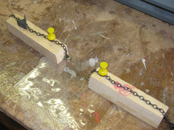
Anchor Chain Stops
Going to make two anchor chain stops.
Start by making notes from my scaled drawing.
Make plastic sheet pieces.
Have chain near by for reference.
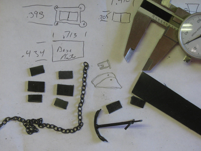
Sand pieces to the correct size.
Two deck plates.
Four side plates.
Two slotted stop plates. (leave long and finish after installing base
on deck)
Below the two base plates are assembled.
Made the two slotted stop plates.
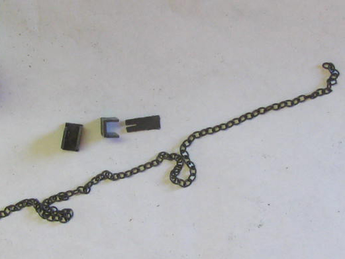
A visual of the anchor chain stop with chain and stop plate sitting
in place.
shaping the sides of the base plate will be done after a few days cement
curing.
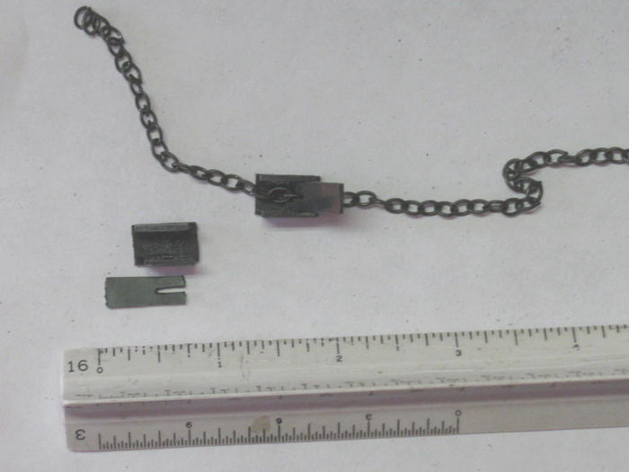
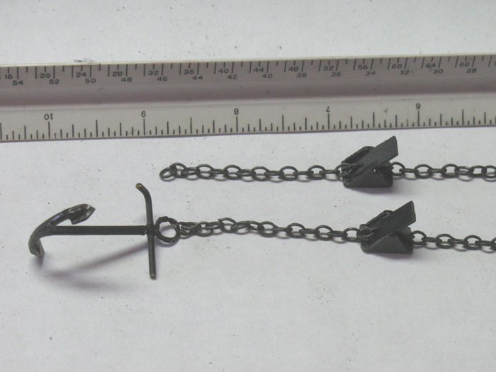
Anchor Chain Stops assembled with chains.
Anchor sitting for look.
The stop plate is still long for handling purposes.
It will be cut to the top of the frame after it cures and I an sure
it will stay together.
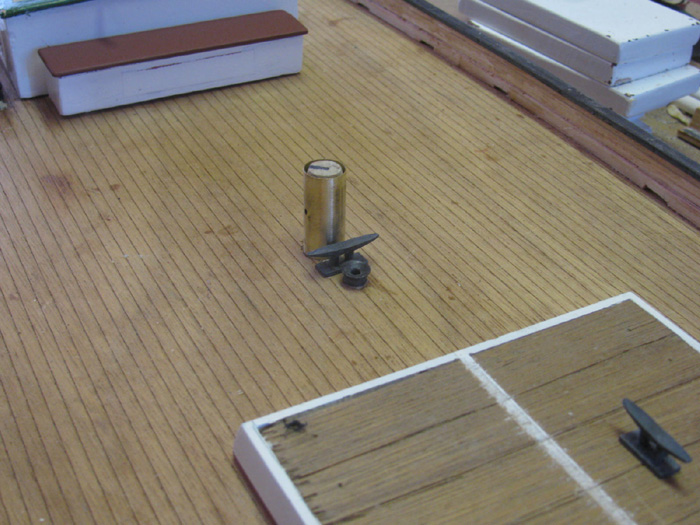
I need to locate and put a hole through the deck where the chain comes
off the windlass and in to the storage locker.
Before I make a hole in the deck, I need to make the part to represent
the pipe and flange.
Holes located and drilled in the deck under the windlass.
Chain and anchor chain stop sitting in place.
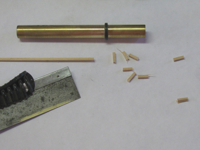
I will be using 1/4" brass tubing and mounting a plastic ring on it
to represent the deck flange.
Here, I have a piece of scrape tubing with two pieces of plastic drilled,
slipped on and glued.
Once the glue cures, I will put this in my drill press and spin it
to turn the rings rounds and to size.
Once I am happy, I will cut the tubing to length separating the two
flanges.
I need to thin the plastic down because at scale, the 1/16" thick that
would be 1.5" on the boat.
After cutting to length, I will stick a round piece of wood in the
bottom of the tubing and glue it in place.
After installing in the deck, I will drop a little glue in to the bottom
of the tubing and drop the end of the chain in to the glue to fix it in
place.
No leaks through the deck.
Turned the plastic to the correct diameter.
Cut the two parts off to length.
Here I am gluing he end of the chain in to the deck flange.
I should have taken a side view.
The flanges are 5/16" long to glue in to the deck.
the black plastic flange is a little less than 1/32".
==========================
Standing Rig
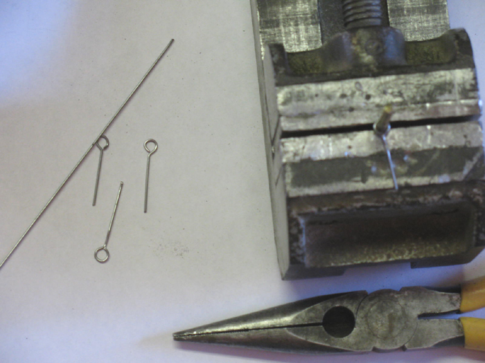
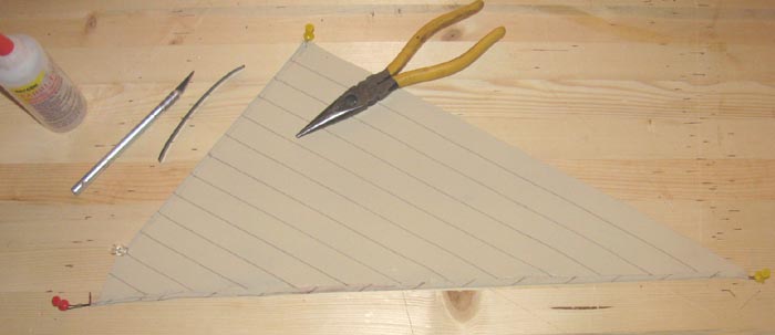
This morning, I made deck eye bolts.
I need 10 just for the deck.
Scaled the eyes off the original drawings.
Pick the wire size. (.032")
Found a pieced of rod that I could bend the wire around to make an
eye with an outside diameter of .188". (about 3/16")
Pliers and needle nose pliers and start bending.
Make a rough bend around the mandrel and finish bending by hand with
pliers.
Used the drawing to locate where the eyes go on the deck.
A short piece of the wire in the Dremel to drill pilot holes in the
deck.
Under the deck is the major frame board that goes from the bow to the
stern.
It is solid from deck to bottom sheet.
These eyes are in place for the photo.
I will remove them and paint the eye black.
When it comes time to install, I will dip the long shank of the eye
in glue and push the shank all the way in down to the eye.
I have been busy working on my Skipjack and building a new Akula II
kit.
Both are ready for a run at the pond.
So now, I have the Alma back on the bench.
Where to start?
How about with the rigging.
I left off making deck eyes and I see the jig is still on the end of
the bench.
I will start by making the eyes needed on the booms.
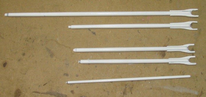
Here are the booms before I start.
Top to bottom.
Main lower boom.
Main upper boom.
Staysail bottom boom.
Staysail upper boom.
Jib boom.
I made the eyes form .020" wire and the bent them around a steel rod
of about 3/32".
I twisted the wire just below the eye and left one leg longer that
would go all the way through the boom so it can be bent over on the other
side of the boom.
These eyes need to carry the weigh and pressure of the sails.
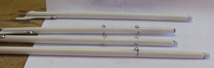
Top to bottom.
Staysail bottom boon. (no eyes yet)
Staysail upper boom.
Main upper boom.
Main bottom boom.
The booms where drilled using a piece of the wire. The the eye side
was drilled with a small drill bit to accommodate the twisted wire section.
After test fitting, I put a couple of CA glue in the hole and on the
twisted wire.
Pushed through with pliers and tapped with small hammer to get the
eye down in the groove I cut with Exacto.
(Yes, I measured the drawing to ge the correct placement.)
Still making eyes.
Need to figure out something to the yoke lift.
Got a feeling these parts will not be scale or anything like the real
thing.
Here is a photo of the Staysail yoke and hardware.
Looks like 2 small eyes and 3 rings.
Now consider the yoke is 1/8" thick.
I am not making those rings or the small eye bolts.
-------------------------
Eyes have been installed and glazing has started.
Sanding is complete and 2 coats of white paint applied.
1 more coat to go.
3 coats of white and several coats of black to build up and edge to
represent the metal strap that the eyes are on. 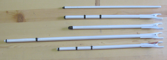
A quick look of Main ail gaff in place.
Anchor Chain pipe in place.
Chain not glued in at this point.
While working on the mast parts, I thought it was time to sand the hand
rails and get them ready for paint.
The sanding is coming along nicely.
Then I realized that I had painted the hull maybe 9 years ago.
The ALMA has been o and off the work bench so many times and shows
a bit of wear.
Maybe a bit more than wear as there are dings and chips in the original
paint.
To paint the hand rail, I will have to mask off the hull.
Well, why not start the repainting of the hull?
Good questions. Why not!
So while I sanded the hand rail with custom made sanding blocks to fit
the narrow boards and the angle of the boards, I block sanded the entire
hull.
Even did some glazing of dings and dents.
The hand rails need to be primered before painting or the balsa wood
will take so many coats of paint.
Might as well tape off the hull bottom which is red primer.
Here the starboard side has been primed.
Here the port side is ready to be primed.
Next I will cover the bottom and uncover the hand rails.
I was going to try priming the bottom and rails a the same time but
I could not make that happen.
The hull had to sit on the rail to paint the bottom.
I did mask the hull in sections so all I have to do is cover the bottom
and remove the hand rail cover tape.
I still have to mask off the deck side of the hull before painting.
The hand rail outside has been taped, primed and painted.
All is/was good.
It all looked good after the white was painted.
Then painting the brown deck line caused issues with the white.
The tape lifted some spots on the white.
Not a big problem but will require patience I don't usually have.
I will let it all dry for a few days while I go back to plumbing in
the house.
Looking at the bow.
I painted the brown line and the white up to the hand rail.
This area is not quite 3/4" wide.
I can see I need to scrape the chain pipe again.
Looking down the side.
Perspective.
I have painted the bottom red, the deck line and the railing side.
The rest still needs to be done.
I am thinking, I need to consider painting some of this with a brush.
Looking at the stern.
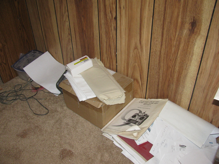
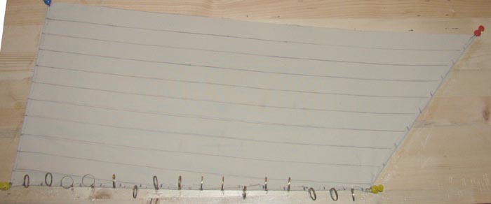
Found the sail cloth.
I have been working everyday with in 5 feet of it for several months.
I just spent 4 days looking for it.
Too cold out in the shop.
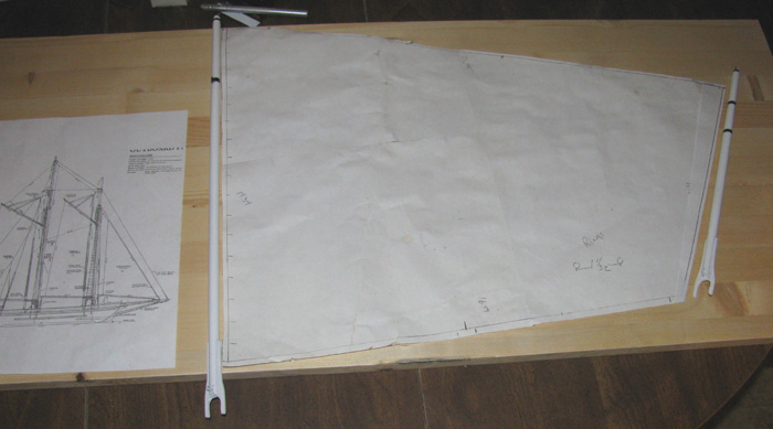
Brought the booms and gaffs inside this morning.
Double checked my paper patterns for the three sails.
I made these more than a year ago.
The stay sail is off by 3/8" on the gaff outer end.
Remarked it so when I lay it on the fabric, I remember to add to the
cut.
Checked the boom and gaff lengths.
The eyes I added a couple of months ago all look to be in the correct
place.
Notice the board everything is sitting on.
That is the bottom of the transportation box.
(Size reference...ALMA drawing is on standard 8.5"x11" paper. Also
Exacto knife at top of image)
This is the main sail pattern with boom and gaff laid on the board.
I was going to use the fabric's finish edge as the luff edge of the
sails.
Turns out the fabric has a really rough, unfinished edge.
Not a problem, I will just need to seal the edge when I cut it so it
does not unravel.
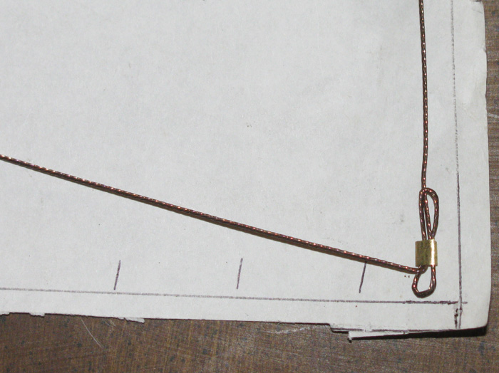
This is the figure 8 in the cable.
.030" cable run through 1/8" brass tubing 3 times.
The cable on the right goes up to the sail head.
The cable to the left goes to the sail clew.
The lower eye hooks to the boom at the yoke.
The upper eye will be buried in the sail cloth when folded and fixed.
Only the lower eye will be seen.
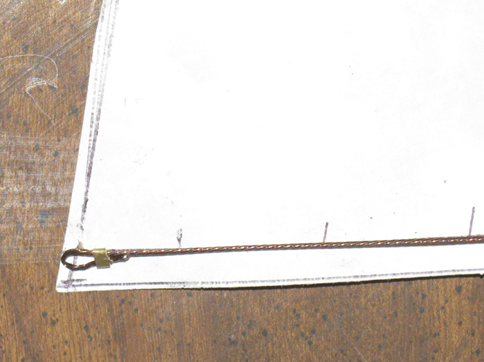
This is the sail clew end.
The .030" cable goes through the 1/16" brass tubing two times.
Only the eye will be seen once the cloth is folded and fixed.
Size reference. The pencil marks above the cable are 1 1/32" apart.
I have made up the main and stay sail cables to this point.
Next will be putting the mast rings on and putting the two top eyes
in the cable.
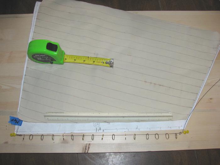
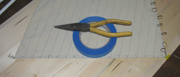
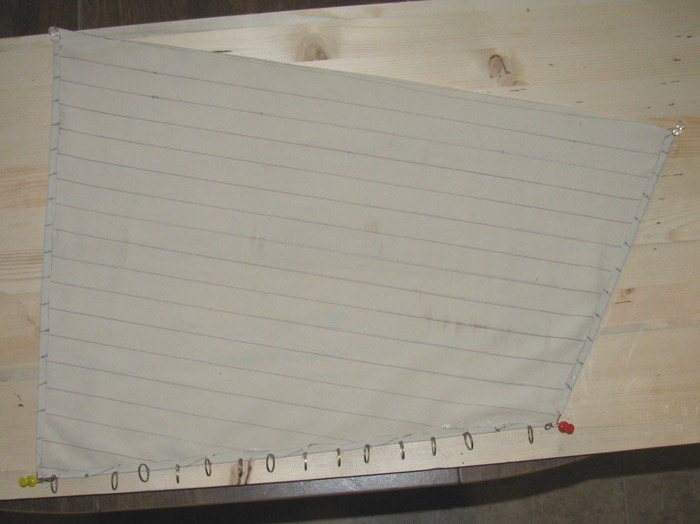
Sails have been rough cut.
Meaning they are about 1/4" over sized.
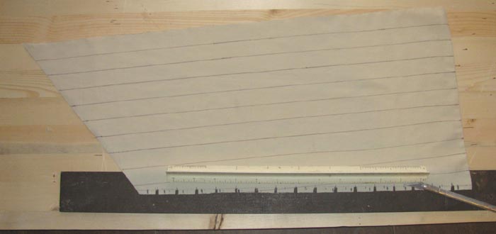
At the bottom is a 12" drafting ruler.
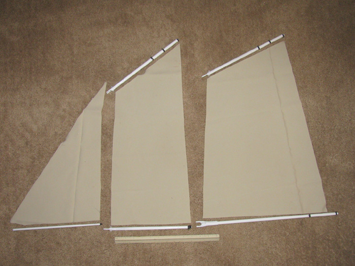
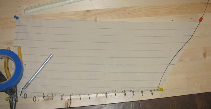
Laid out the sail panel lines.
Ran a brown permanent marker along a steel ruler.
Now I have to decide if I will do the same on the other side of the
sails.
In photos, the panels are not seen on the sun side but are seen on
the side away from the sun.
I am gone to leave the sails sitting on the floor for a few days and
see how I like it.
I will turn the jib over to the unlined side so I can see both together.
I didn't think I was going to like the lines.
I did a sample piece of cloth just to see how it would look.
As of now, I do like it.
Mounting the sails to the support cables.
Starting with the main sail.
Measuring the location of the mast rings.
The cable is held in place using push pins through the cable end eye
loops
Next I will cut the sail to allow the mast rings to inset in to the
sail.
Yes, I have a piece of fabric I am doing test on before I move to the
sail itself.
Sail mast ring inlets cut.
Folding tabs over the cable.
Using a fabric bonder.
All but the ends completed.
I need to make different cuts to fold the corners.
Now to let it all cure before putting stress on it.
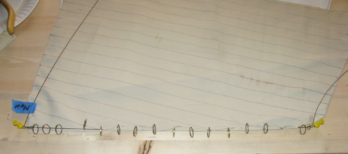
The bottom edge of the main sail has been folded around the cable.
Completed main sail.
There is a stress cable top bottom and mast side of the sail
The cable has eyes at each corner for connecting to the running rig.
(the push pins are through the eyes to hold it all tight while bonding
the fabric)
Location of mast rings laid out on sail.
Notches cut with Exacto knife.
(first layout turned out to be incorrect, thus all the extra marks)
Next is to lay the stress cable on the sail and start folding over
the fabric as I bond each tab.
Mast rings in place and fabric folder over stress cable.
Will let it cure for a couple of hours then finish the top and bottom
edges.
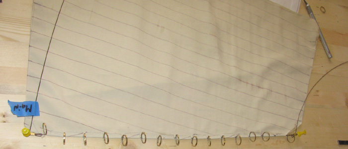
Staysail complete
Ran in to a major problem yesterday.
The plastic bottle of fabric bonder got so cold over night that the
bottle cracked.
Some of the bonder leaked out and it all hardened.
Fortunately, I had to go to town today and was able to replace it with
new.
The new was so much thinner than the old.
I had had that old bottle about 2 years waiting to be used.
It appears it had thickened up but I was not aware as I used it until
today when the new stuff went on so much easier.
Even allowed me to move the fabric after contact which the original
did not. (too thick)
Only need to put a partial cable in the foot and it will be done.
The foot is laced on to the jib boom from the clew to the second panel
line from the stay cable.
The cable will take the lacing strain, same as the other sails.
This is the jib and it is the smallest sail.
The luff (bottom of image) is 21" and the foot (left side of image)
is 9".
Cable installed in to the foot of the jib.
========================
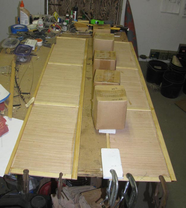
Transportation box
Cut all the lumber to size.
Mocked it up on the bench.
ALMA sitting on bottom board with 3 sides taped in place to see what
I have.
Staysail mast laying on deck.
Looking at front of boat.
Looks like plenty of room for the masts and standing rig to be up on
foam blocks up off the deck.
View of stern.
Looks like I will have lots of room.
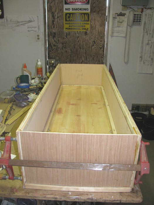
Building the transport box.
The only trim strip being glued is under the channel iron.
The other strips are being used as spacers for now.
The sides are glued to the bottom board.
The bolt hardware is installed.
Looking from the bottom you can see one of the "L" corner brackets inlet
in to the bottom board.
There is also a blind nut in between the bottom board and the side
board.
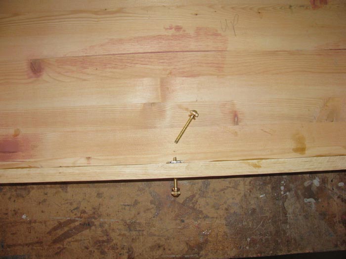
The bolt goes through the Side panel (not show) through the side board,
through the blind nut, through the "L" bracket to support the bottom board
and not have all the stress on the side board.
I will glaze over the "L" bracket to hide it.
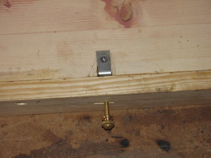
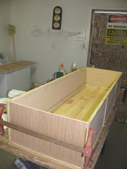
Looking at the "L" bracket from the top side, you can see the blind
nut, the "L" bracket and the bolt coming through the side board,
blind nut and the "L" bracket.
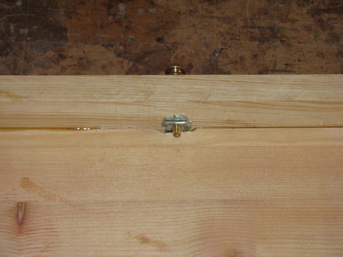
Another look.
The gap between the side board and the bolt nut is where the side panel
will be.
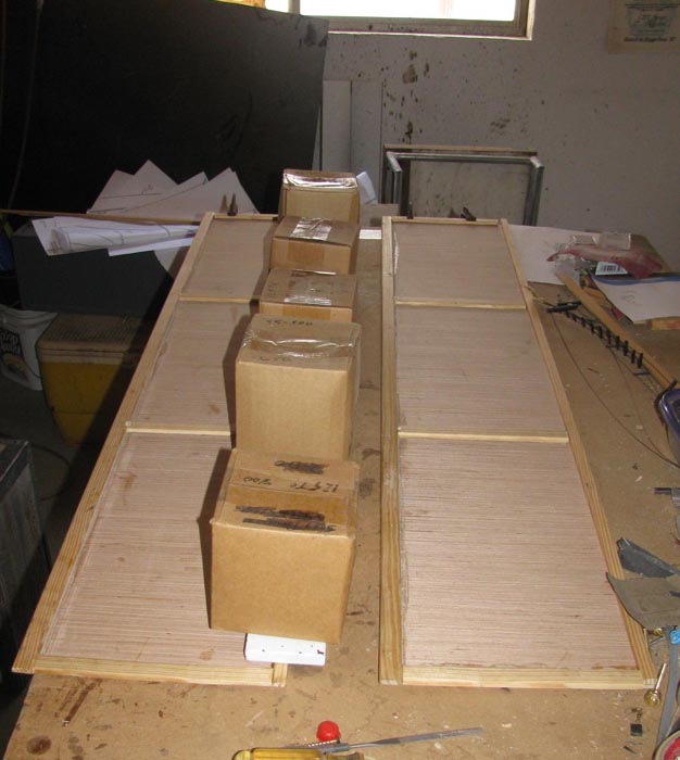
Side trim pieces glued and weighted.
The one on the left has just been glued.
The boxes are 20 pounds for the small ones and 22 pounds for the large
ones.
The boxes are sitting on the ballast blocks which are about 3 pounds
each.
(guessing, I haven't weight them)
The ends are clamped.
Box ends glued in place.
Just noticed the photos show only one clamp arm but there are two there.
From an angle.
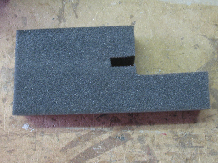
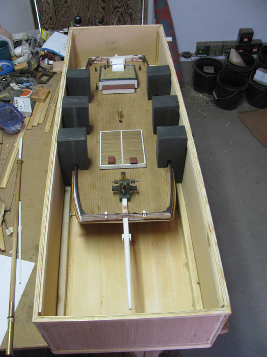
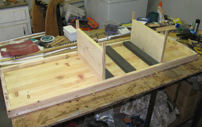
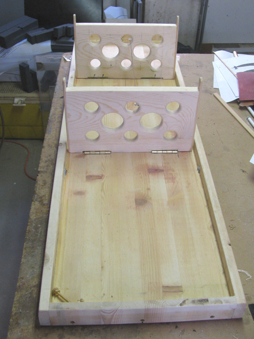
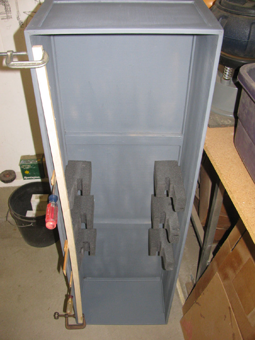
With the top not installed, I will make the hull supports.
3 bottom supports are 2" wide x 1" thick foam.
The spacing looks wrong but remember there is 10" bow sprint before
the hull starts.
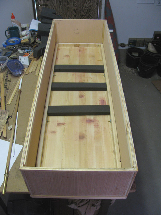
Using 3" thick foam, I made 6 pieces 2" wide that will hold the hull
centered in the box and will put down presser on the hull at the deck.
There will be about 3/16" compression on the foam.
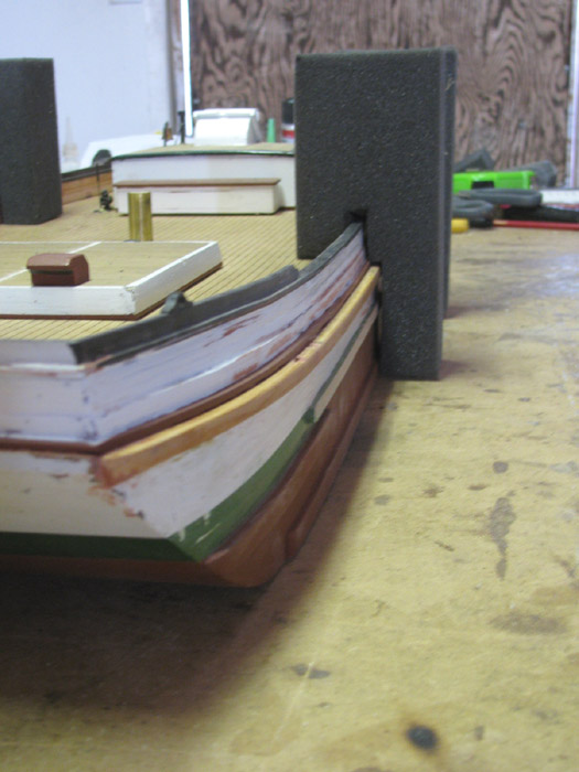
Here are 5 of the 6 foam pieces sitting on the hull so I can see how
they will fit.
There will be pressure on the deck but ot on the railing. (just what
I want)
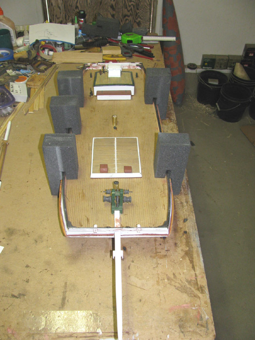
Looking down the side of the hull, I can see the gap for the railing.
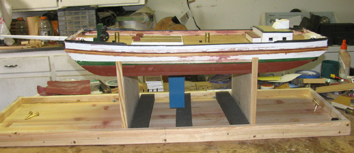
All 6 supports sitting on the hull.
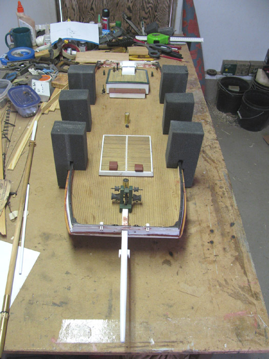
Hull in the box with all 6 supports in place.
The supports sit on top of the bottom supports.
I still need bow and stern blocks but will wait until I have all the
rigging in place.
I need to know exactly where the bow sprint cables and rudder control
lines will be.
View from the stern.
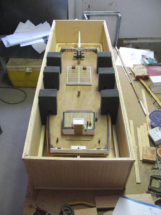
In the transportation box.
Hull with 6 foam pieces that will keep the hull in place.
The main mast, fore mast, 2 booms and 2 gaff booms.
I make 2 foam blocks the sit on the deck between the rails (slightly
compressed against the railing) and over the mast brass tubing step.
Once I get the standing rigging installed, and the sails on the masts,
I will make a small notch for the masts to sit in.
The notch will be undersized to pinch the mast so they do not move
around during transport.
The sails and rigging will lay between the masts.
I have cut the 2 support stand boards.
Currently on work bench letting the glue cure.
They will fold down under the hull.
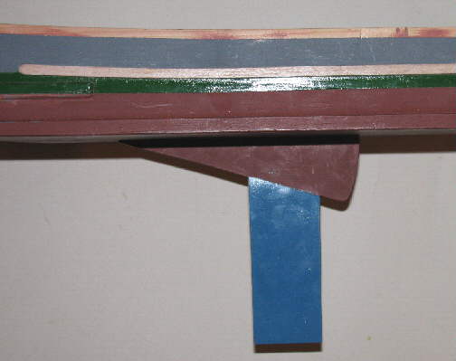
Why are the stands needed.
There is a keel that extends about 1.75" below the hull and I added
more to add a cheater ballast weight at the bottom of the false keel.
Total depth is 6.5".
The stand will be used when the removable keel is in place.
(keel was made way back at the beginning of construction)
Built 2 stand pieces.
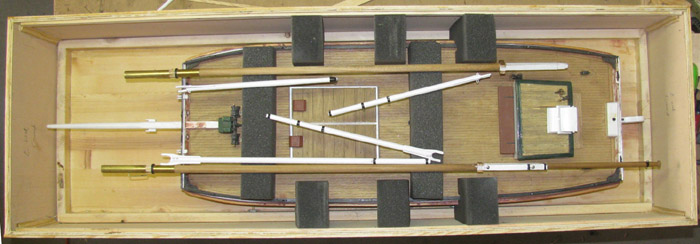
Here they are laying down in the transport position.
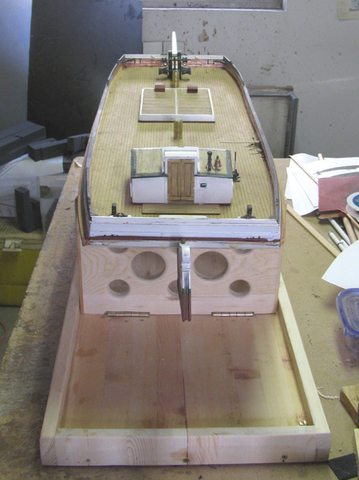
I put the hull on the foam blocks and I have 1/4" clearance.
I put 100 pounds on the deck and could not compress the foam enough
to get the hull to touch the stands.
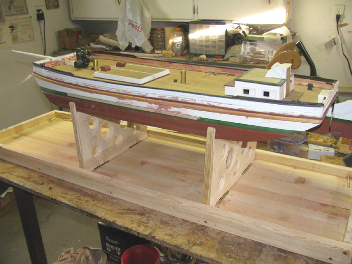
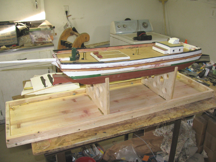
Stands in the up position.
Stands up and hull sitting on stand with the keel in place.
There is 1/4" clearance from the bottom of the keel to the foam block
but if I need more room,
I can always cut the foam to get another 1".
Stand boards with holes to remove weight.
Sanded and ready for hinges to be reinstalled.
Hinges installed.
Cable between stand boards made up and put in place.
The cable keeps the stand boards from falling down.
Hull placed on stand.
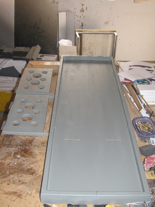
I was at the hardware store and was looking fro Krylon gray primer.
The store no longer carries the Krylon gray primer because all the
new Krylon paints have primer in them.
And no flat gray paint.
-----
So, I bought another brand.
sprayed the bottom board and the 2 stand boards.
after an hour, I went out to spray second coat.
It was not dry. It was not tacky. It was wet.
Waited another hour.
Now, it is tacky and I got the second coat on there.
Moved from the outside work bench to the inside work bench.
It feels like rain and the weather says freezing tonight and tomorrow.
Another issue is, this primer does not cover well.
Not like the Krylon did.
I will let this sit for a day or 2.
If this does not work out, my plan B is to get some outdoor, latex
paint to match the primer gray and bush paint the box.
The paint I put on the house and outbuildings looks good after 2 years.
Even though I bushed it on with a 4" brush, there are no brush marks.
Has held up to 24 hour sun light, rain, snow and really hot summer
days.
I am going to hold off priming the upper box until I know how this primer
cures.
Moving on with the transportation box.
Gluing in the top panel of the box.
(each box weights either 20 pounds or 24 pounds. I think that will
hold it down while the glue cures)
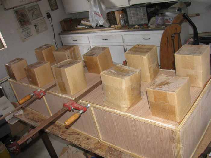
Top of box trim strips will be next.
All trim boards are installed.
Sanding to make all joints smooth is complete.
Used air and damp rag to remove the dust.
Applied glazing to all joint seams.
While doing this, I turned on the heat to warm up the shop to help
things cure.
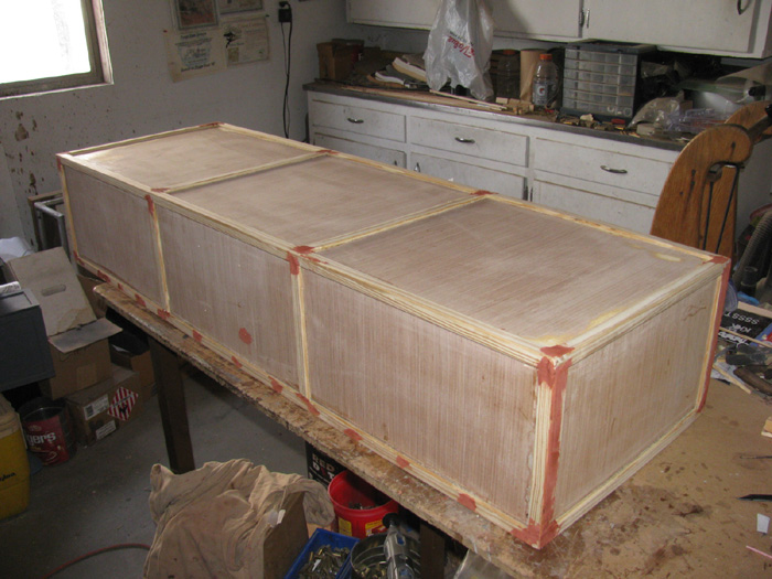
Sanding of glaze completed.
Now to apply the primer.
2 coats of primer applied to outside of transportation box.
2 coats applied to 1 side of stand boards.
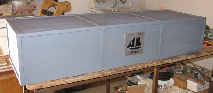
ALMA transportation box priming/painting completed.
Emblem mounted.
Got a little time in the shop.
The foam glued in to the top has cured.
Repaired the rudder upper hinge. (resoldered and built up plastic strap)
I broke it off trying to get the top of the box off the bottom board
with the hull in the box.
Turns out the foam is too tight to the sides of the hull and I think
there is too much pressure on the hand rails.
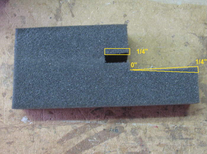
So, I modified the foam.
I did not get photos that came out.
Trying to take photos down inside the box was a problem when I found
out I did not have enough battery for the flash. (oops)
But I can still show what I did using a photo of the origin foam block.
I did the cutting on the foam down in the box.
The foam inside the yellow lines was removed.
Tried to cut it with a razor saw but that was a fail.
I tried the Dremel with a 1.25" dia thin grinding wheel and slowly
cut he foam away.
Actually when very quickly with melting the foam.
6 blocks of foam took about 6 minutes to reshape.
Tested the blocks with the hull again and all went very well.
Dropped down without having to shake and push.
Lifted up easy enough but I could tell the foam was holding on to the
sides of the hull.
Lifting the box lid, slowly, I could feel the hull slipping down.
This was good and I did not get ahead of the hull dropping and the
hull stayed on the bottom board foam.
I think for now, I will leave it like this.
The top fits very tight on to the bottom board.
A quick look shows that one side of the box is not straight.
The side bends inward.
The bottom boards is beveled to push the sides out straight but the
side does not engage the bottom board before the foam comes in contact
with the hull railing.
The fix is to reshape the side panel.
Here, I have clamps and wedges to bring the side out straight.
I will let it sit this way for a few days while I move on to other
projects.
I cleaned up the shop and I cleaned off the work bench of all the cut
plastic, paper dust and miscellaneous parts.
While I wait on the side to straight up, I thought I would work on
the Akula II.
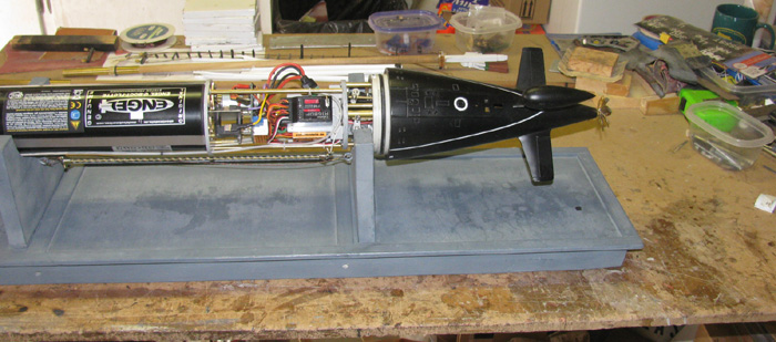
During water testing, I could see air bubbles coming up at the stern.
I opened up the access hatch and turned the boat upside down in the
water and with a flash light I looked for where the air was coming from.
There are several through bulkhead fittings.
Rudder, stern planes, piston inlet/outlet, pressure sensor and a 1/8"
hole I don't remember what it was for.
I took a length of .028" brass wire and I pushed it through the access
opening and in to the 1/8" hole.
As I pushed, I watched on the front side of the bulkhead to see where
the wire came through.
There it was.
Inside a clear plastic tube.
Okay, what is this?
Followed the tube and it went to the back side of the pressure sensor.
This explains the bubbles.
There is about 16" of this plastic tubing.
The tubing is just there to get a differential pressure from outside
the hull to inside the hull.
This tube slowly releases air and fills with water.
Not an issue at all.
Next, I plan to bypass the Hall's sensor.
It was optional and I put it in having never used one.
My opinion is, it works really well and as it suppose to.
How ever, my transmitter does not have a control sensitive enough to
use the full function of the Hall's Sensor.
The jump between clicks on my transmitter knob are too far apart and
the piston moves in steps.
I am going to set it back to manual control.
As soon as I figure out the instructions.
The English translation is not explicate enough.
There will be guessing. involved.
==========
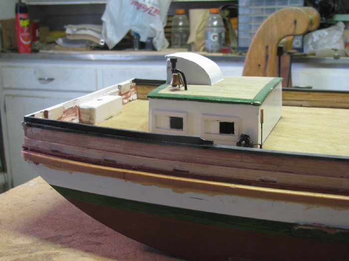
A look at the sails on the masts.
Back to working on the hull.
I want to paint the white on the inside deck rail.
But the rail being balsa wood, has in the past soaked up so much paint
and did not cover well, I decided to clear coat the deck and the inside
rail.
Hoping the clear coat which dries really fast will seal the balsa wood
so the white will not just soak in but cover.
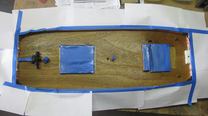
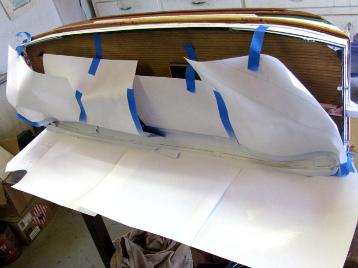
Taped off the at the railing so I could clear coat the deck and inside
railing.
I also did the forward hatch cover but I didn't get it in the photo.
It's still outside.
The bumps in the tape at railing rises and cleats under the tape.
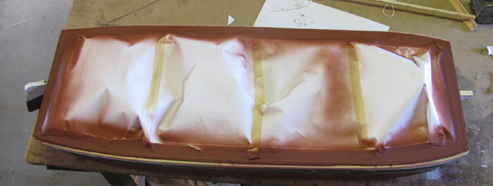
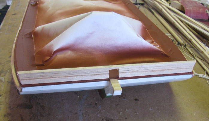
Finally back to painting.
Taped off and first coat applied.
Tack coat.
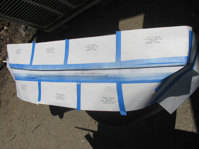
About the protective paper?
I found a box of return envelopes I had printed back in the 80's.
They were sitting in a pile of stuff destined for the dump.
Must be couple of hundred.
Figured I could use them for paint protection, then toss them out.
Sept 1, 2018
Back to the ALMA.
Working on paint.
Doing the right side inside.
The painting of white is now complete. (I sure hoe so)
The green is next after I let the white cure for a day or two.
|