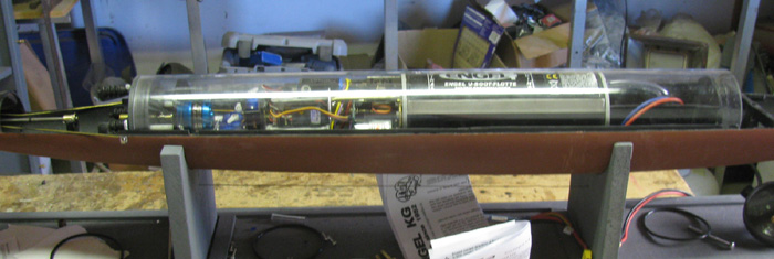
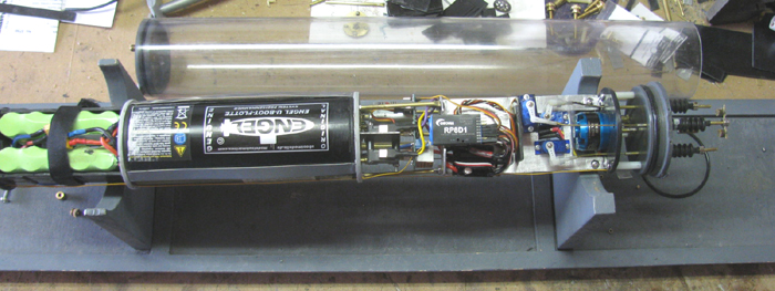
| This a total build of a new cylinder, electronics tray and ballast
system.
I have been running my Engel's Akula II with very good results.
I really like the piston ballast system.
I did some measuring and I think I can put the Engel's system in the
Skipjack.
I have gathered up all the parts needed.
Even have a longer cylinder tube.
I have laid out the parts on the work bench and found I may not have
room.
The piston will be about as long as my current ballast safety tank
but the piston has a lead screw that doubles the length of the piston.
Won't come close to fitting without some major changes.
I can get some of the length needed by rearranging the electronics
tray.
I will be removing the water pump and the speed controller for the
water pump.
But that does not get me what I need.
Yesterday, I assembles the Skipjack and put in the water to do some
testing.
I submerged and surfaced the boat three times to get all the air out
of the ballast balloon.
Then I submerged the boat to the top of the sail just above the water.
I carefully submerged the boat to get half the periscope under water.
I then lifted the boat out of the water and tipped it bow up.
This will keep the water from draining from the ballast balloon.
I opened the hull.
Turned off the power.
Removed the pressure bolts that hold the end caps on under pressure.
I removed the front end cap and slid the battery out.
I then pulled the electronics tray and ballast system out the back
of the cylinder.
I removed the ballast safety tank from the system.
Drained all the water in to a measuring cup.
This will give me the total water needed to dive the boat with a little
negative trim.
450 ml is what I got.
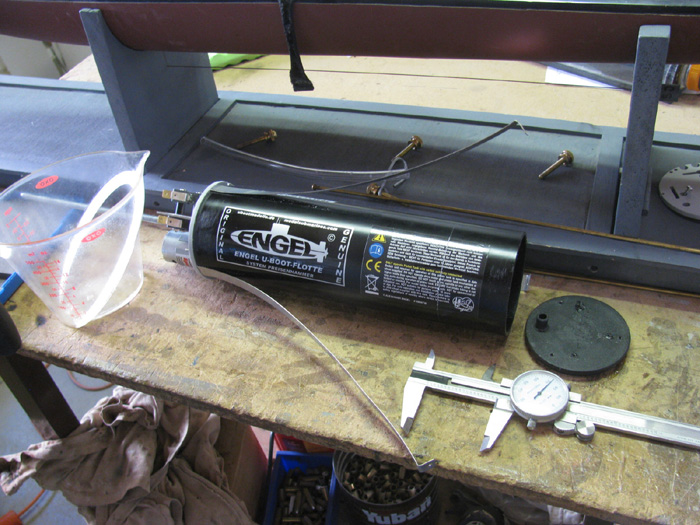
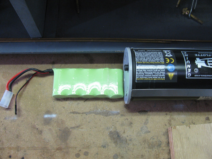
Now to test the Engel's piston.
It is a 750 ml piston tank.
I ran the lead screw to full dive.
Filled with water and then poured in to a measuring cut.
What do you know? ...750 ml.
I need the piston to be about 2" shorted overall.
I looked at the Engel's piston drawing and ran the numbers given.
I was missing something because my numbers did not match Engel's.
But the volume numbers where good.
So, I did my own math with a ruler and pencil.
The tank is 8" long.
Calculations say, I need about 6" of tank.
That's translates in to 2" shorter overall.
Note: Piston tank should be longer.
Having run this boat for some time, I want to issue a change notice.
The ballast tank should be longer.
My numbers are correct but they are right on the line of being too
small.
If I were to do this again, I would cut the ballast piston to a length
of 7". |
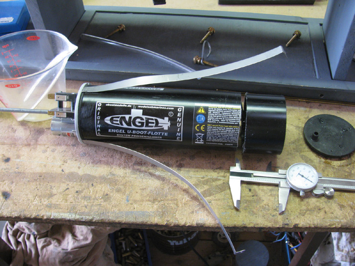
I measured 600 ml of water in the cup and poured it in to the piston
tank.
I have removed the water inlet cap and physically measured the inside
of the tank including the piston itself.
600 ml is 150 ml more than needed so I will start there.
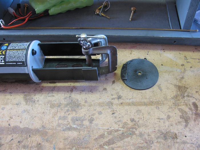
I marked the cylinder at 1.80" from the inlet side.
Too much stuff on the motor side.
Here is a photo of the tank with the cut mark on the right end.
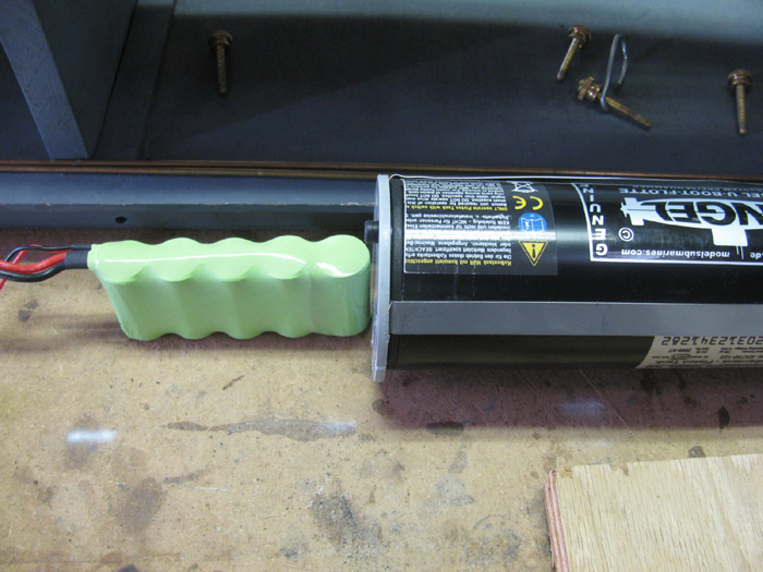
i used the calipers to scribe the mark using the end of the tank as
my guide.
Here the tank has been cut.
Need to clean p the cut and sand the edges smooth.
Finished with a rough cloth to shine the plastic cylinder.
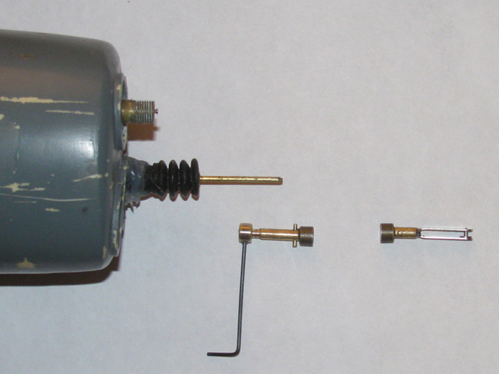
Run the pistol to full dive to get the length of the screw.
Marked with marker at the limit switch.
Pulled the piston out of the cylinder.
Then I ran the screw all the way out of the drive gear and had the
screw and piston separate from the tank.
I cut the screw on the mark and ground a taper on the end of the screw
to match the original. (sitting on table to the right)
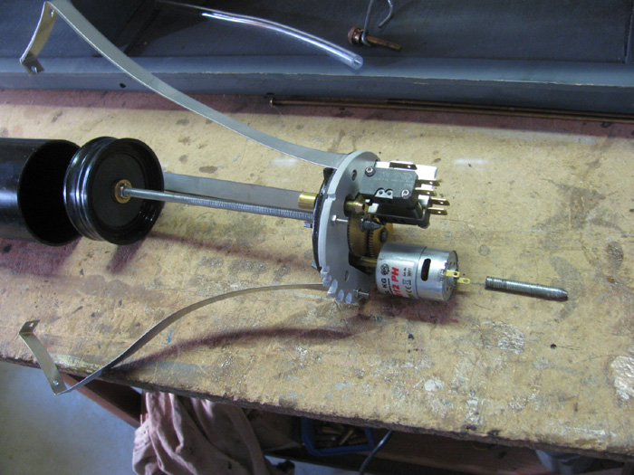
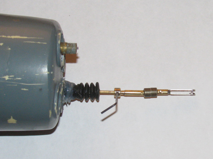
Close up of gears and screw sitting just past the limit switch activator.
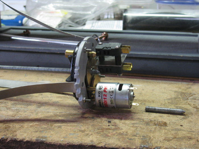
Cleaned up the cylinder and piston to get all cutting particles off.
Reassemble the piston.
Ran the screw full in and full out to make sure I had the correct length
on the screw.
Turns out, I need to remove about 1/8" from the screw end.
I can do that with the piston assembled.
So on to reassembling the piston.
Check again that the piston and tank are clean.
Put so high speed water proof axle grease on the piston edge and inside
the tank.
Slip the piston in to the tank and make sure the piston edge is straight
and not folder over on itself.
The piston slides in rather smoothly.
Same when pulling out.
Get the end caps on making sure the o-ring on the inlet side is not
pinched or folder.
The motor end has a rubber washer and no o-ring.
Just a compression fit.
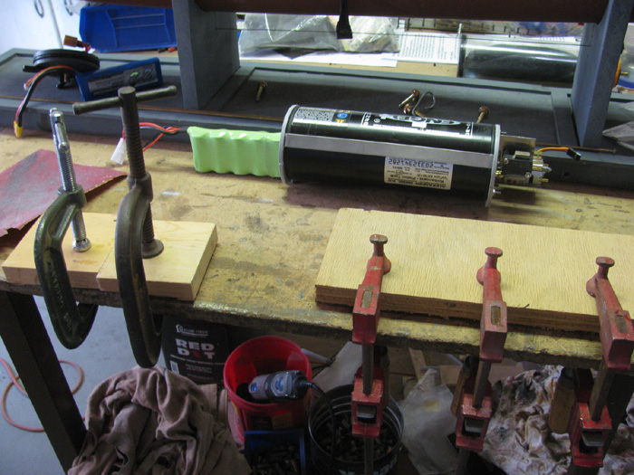
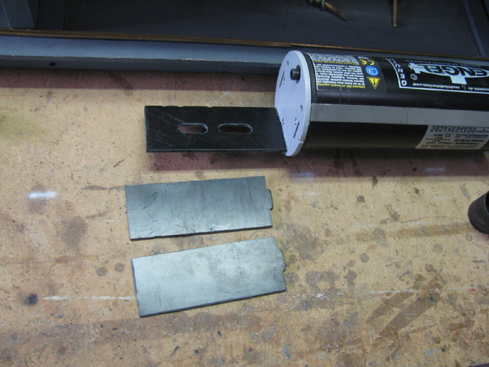
Now that piston is reassembled, the pressure bands need t be fit, cut
and drilled for the retaining screw.
Retaining straps bent and drilled for screws.
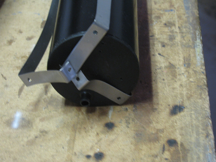
Straps bent and two are cut. (used grinding wheel on Dremel)
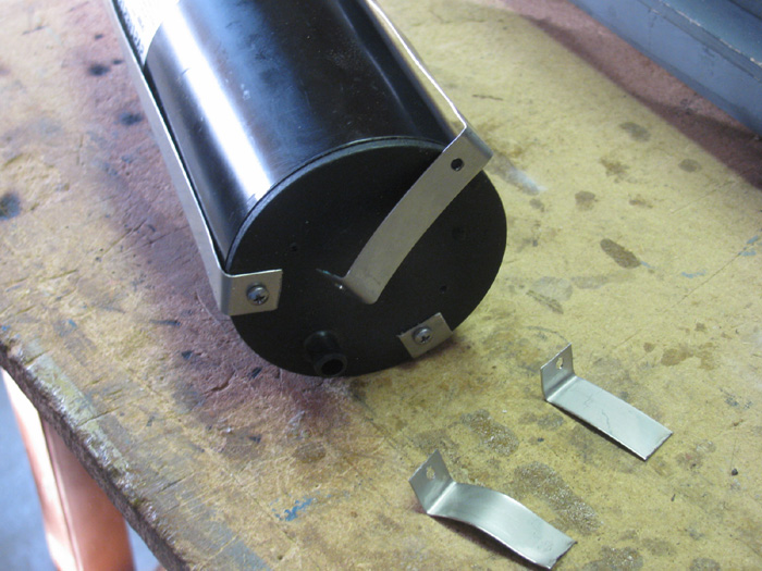
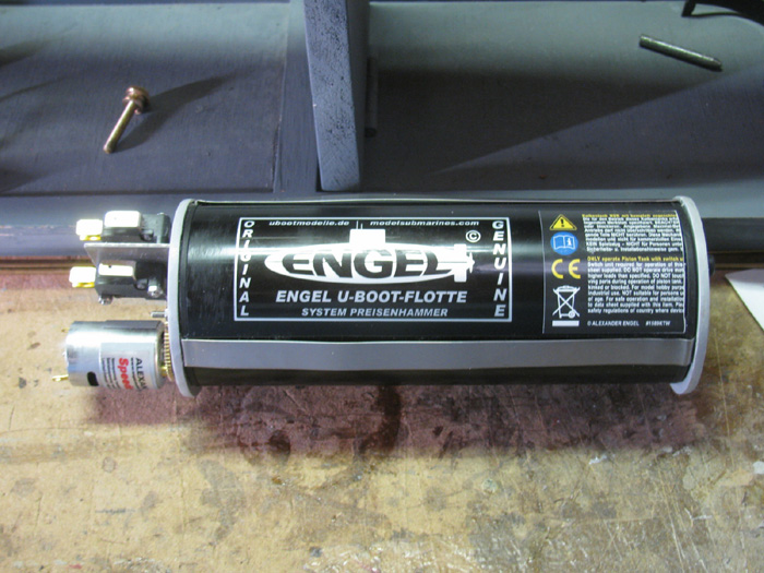
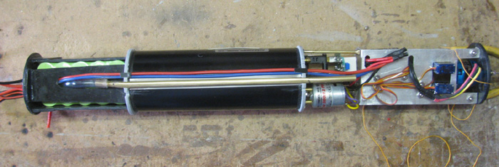
Here, I have a 750 ml piston tank modified to a 600 ml piston ballast
tank.
The first thing tomorrow, I will be working on the lead screw to shorten
it 1/8" and checking to make sure the limit switched work correctly.
With this tank, I can not start the layout of other parts that go in
the cylinder.
---------------------------
I only had about an hour to work in the shop.
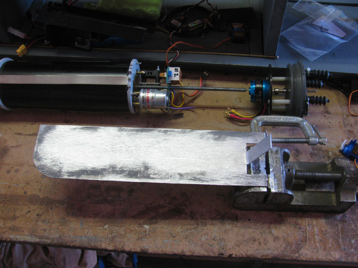
What to do?
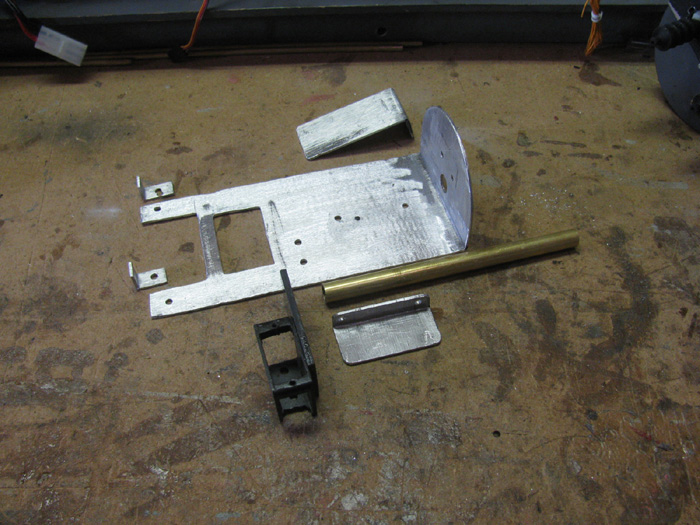
Layout the parts on the work bench to see if it will all fit in the
cylinder.
Turns out that cutting 1.80" off the cylinder and then the threaded
piston screw, it looks like I need about 21' to get everything in.
My cylinder is 24" plus about 1/2" inside the end caps.
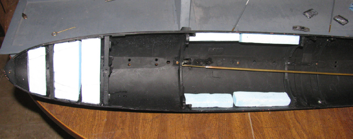
After seeing I have the room, I will start with the easy stuff and the
things that have a given length I can not change.
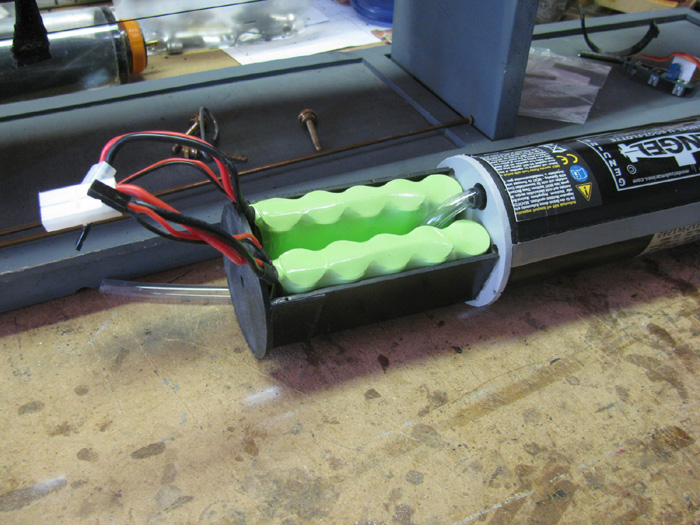
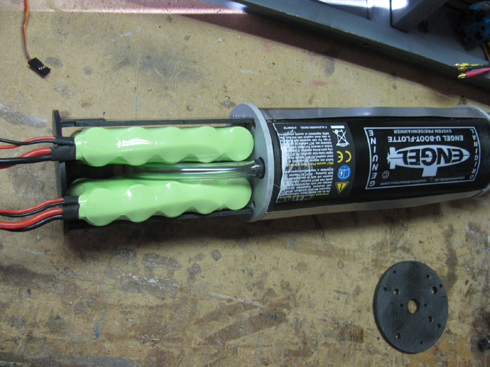
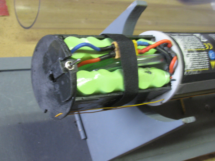
Batteries, they go all the way in the front in front of the ballast
piston.
I have the piston and the batteries.
There will be 2 battery packs to make the 12 volts needed.
Only need 1 to get the measurements to make a battery tray that will
be mounted on the frame on the front of the piston.
Okay, time to cut sheet plastic and glue pieces together to make the
parts thick enough.
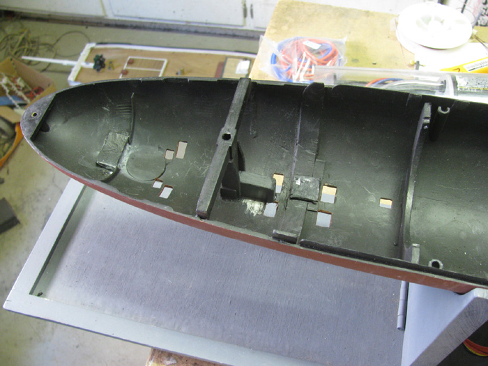
There are 3 notches in the front frame for the battery tray to plug
in to when glued in place. (most surface to bon)
I got my sheet of plastic out and measured and marked for the pieces
I will need.
Cut them out and lightly sanded one side of each part to give the plastic
cement a rough surface to bond to.
Using a clean rag, I wiped the cement on 2 surfaces at a time because
it dried very quickly.
Once covered with glue, I placed the 2 faces together and slid them
around to make a good contact of the glue to both surfaces.
Lined on 2 edges and set on table where I could set a board on top
and then clamp to the bench.
Did that with the other pieces.
One on the left is the bottom piece and the ones on the right will
be the sides of the battery tray.
Will let cure over night.
I have shaped the 3 [pieces for the battery tray.
The tank frame has grooves for the tray tongues.
The bottom being test fitted.
The 2 sides sitting on the bench.
Putting spacers on the ends of the bottom and sides to get more gluing
surface to the end piece.
Two 6 volt battery packs in the tray.
The boat systems runs on 12 volts.
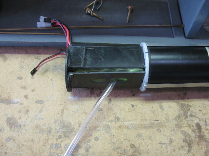
Look at the bottom of the tray with tank inlet/outlet hose in place
for a look. (making sure I got the slots big enough)
Oct 7
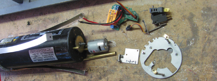
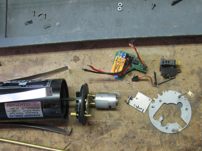
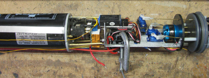
Time to disassemble the original electronics tray.
7 minutes later, I have parts.
Only the motor remains on the rear end cap standoff frame.
Rx, water pump and speed controller will not be used.
Main motor and speed controller, 3 servos, Pitch controller,
Fail Safe (depends on whether the ballast controller has a fail safe
built in)
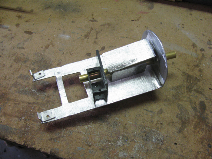
Cut a piece of 1/8" aluminum sheet to width and cut over length of what
I think I need.
Bending the end tabs that will mount to the motor frame.
Other end will bolt to the piston frame.
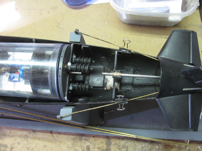
Oct 8
Test fit to find the needed length of the 3 spacer rods that goes between
the rear piston frame and the motor frame.
The Engels rods are solid brass.
I do not have solid brass rod over 1/8".
To small.
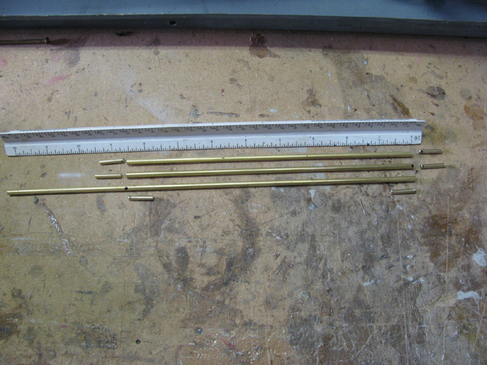
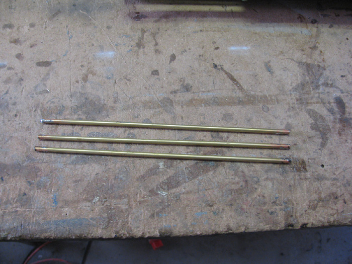
The fix is to use tubing.
Find brass tubing that is smaller than the metric bolts so I can thread
them.
Then find brass tubing to step up the size of the piece to 1/8".
Long tubing is 1/8" and the small pieces slip in to the 1/8" tube and
will be soldered.
The measurement for the rod lengths is 8.5".
I cut the pieces that slip inside a little long so if I need to shorten
the long rods, I can.
Up to a 1/4" on each end. (1/2" total)
Flux the inside of the long tubes and the outside of the short pieces.
Making 3 standoff pieces.
Here the short piece is being pushed in to the long tube using the
soldering iron to keep the solder melted until the short piece is flush
with the end of the long piece.
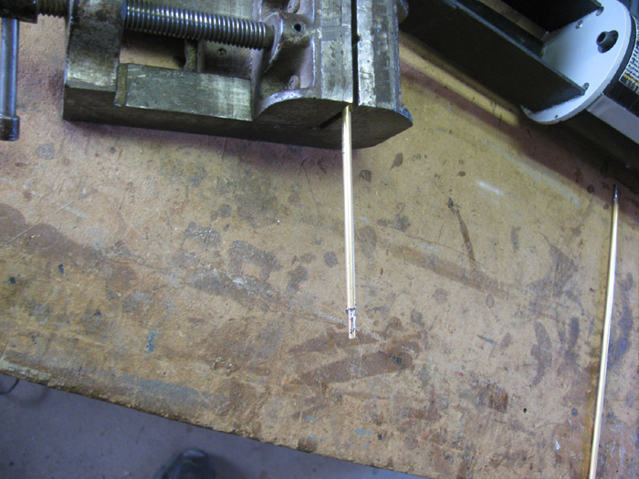
3 completed standoff rods.
Need to find a tap that fits the nut that goes on the bolts in the
piston frame.
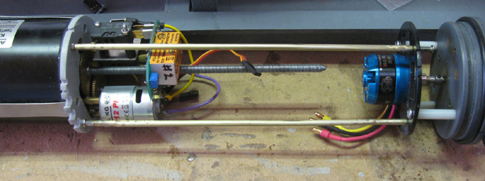
Standoff rods threaded. (3 mm)
Here are 2 rods in place.
Third goes on back side.
Need to do the final measuring.
The gap from the end of the threaded piston rod to the propeller motor
can be reduced but I need to make sure there is room for the other electronics
first.
Still looking, I see that the front end of the piston is where I want
it so the extra room at the back is an added bonus.
Oct 11th
This morning I installed the Hall's Sensor.
I am writing a web page about this but it is running long, so here
is the short version.
The sensor is bonded on a 1/4" strip with the sensor and Rx wires on
it.
Then there are magnets to install on the center reduction gear.
The first time I did this, I found that it was not very easy.
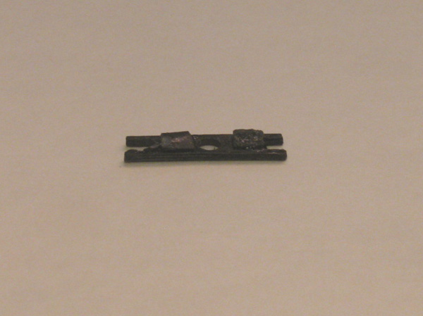
After several tries, I made a small jib to help hold the magnets in
place.
They are so strong that once the first magnet is installed, the rest
want to jump over to the first.
So I made a plastic bar that is held in place by the gear shaft.
On each end of the plastic bar, I files a square notch the size of
the magnets. 1/8" cubes.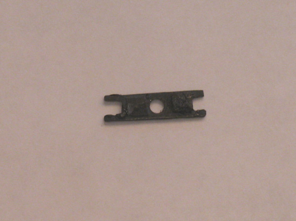
I put something on the bottom of the jig so it would stay above the
CA,
The 1st block was put on with my fingers and then move to get the bar
on.
The bar keeps the magnet 2 mm from the sensor.
Installing the second magnet was a matter of a very small drop of CA
glue and then placing the second cube in to the notch.
There is a process to find the N-S orientation of the magnets but it
is not hard at all.
Put the 4 cubes on a flat non metal surface.
Hold 1 cube down with a finger and slip the second block close to the
first.
At about 1.5" the second cube will jump to the first.
These 2 are not sitting N to S cube to cube and the sides are now also
orientated to the strongest mating.
Hold down the 2 cubes with your finger and slide the third cube near
the 2 cubes.
It will jump to the 2 but if it lands not in line, do it again until
they form a 3 block line.
Yep, the same with the fourth cube.
Once you have 4 cubes in line, you can mark them so you know where
N or S is.
Not important which it is as long as all the cubes are in a straight
line before marking.
I used a black marker only find that it wipes off while trying to place
the cubes. (Remember they are 1/8" cubes)
I finally used a drop of paint.
Put a drop of paint on the top of each cube while they are connected.
Next, paint one end of the first block in the line. Use a different
color for this so you can tell top from sides.
Let the paint dry.
Now separate the painted block from the other 3.
Do not loose orientation.
Drop of paint on the end of the second cube. Let dry.
Separate and paint third block.
Paint end. Let dry.
Separate the third cube and do not let the last cube move.
Paint the same end as the rest.
Let the paint dry before handling..
The magnets will be mounted on the gear with 2 cubes having the top
paint up and the other color towards the gear teeth.
A small drop of CA glue and hold in place a few seconds.
With the jib bar in place, install the second cube the same way.
Top paint up and the side paint towards the gear teeth.
Let set a minute or two.
Remove the jib bar.
and position 90 degrees from first 2 cubes.
CA in place with the side paint towards the gear center.
Now you should have alternating N-S-N-S magnets on the gear.
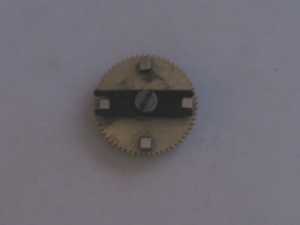
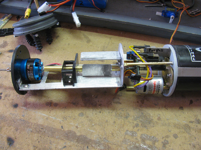
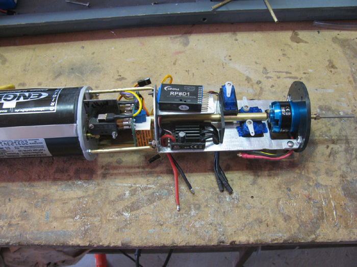
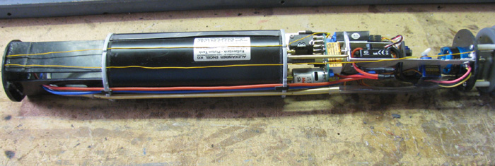
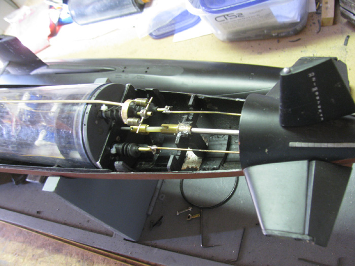
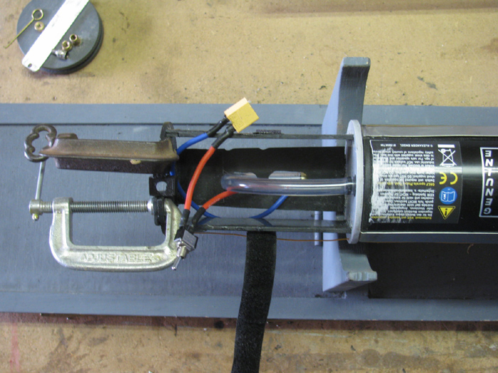
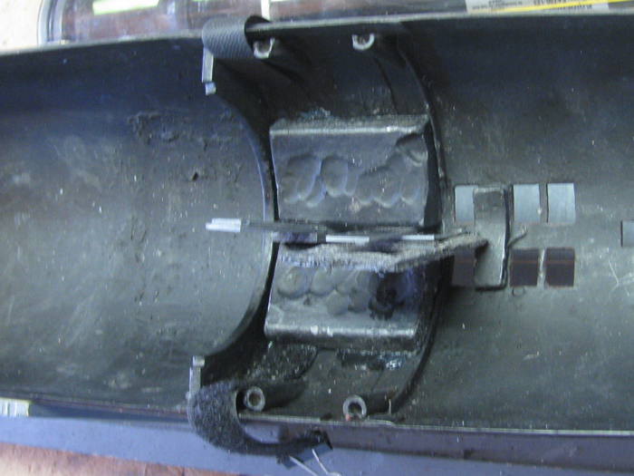
Hall's Sensor and magnets installed.
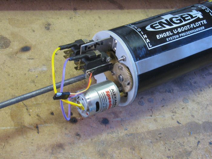
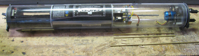
I was able to find the brass tubing I needed for the plumbing.
Here the tubing is installed under the ballast tank.
Hose is installed on the front and back of the ballast tank and to
the brass tubing.
The brass tubing had to be bent at each end to clear the wtc and get
the hose on the tubing.
I also flattened the tubing between the tank frames so it would go
in to the wtc without dragging on the wtc wall.
Plastic tubing from tank to under side of tray to brass tubing.
Oct 14th
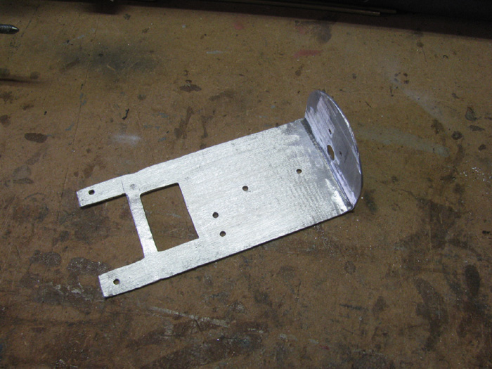
Electronics tray.
After making 2 prototype that did not quite work out, I went back to
the aluminum plate.
I used the plastic one to copy to the aluminum where it was correct.
Then I bent the front end up 90 degrees.
The holes you see drilled in to the plate came as I move along in the
process.
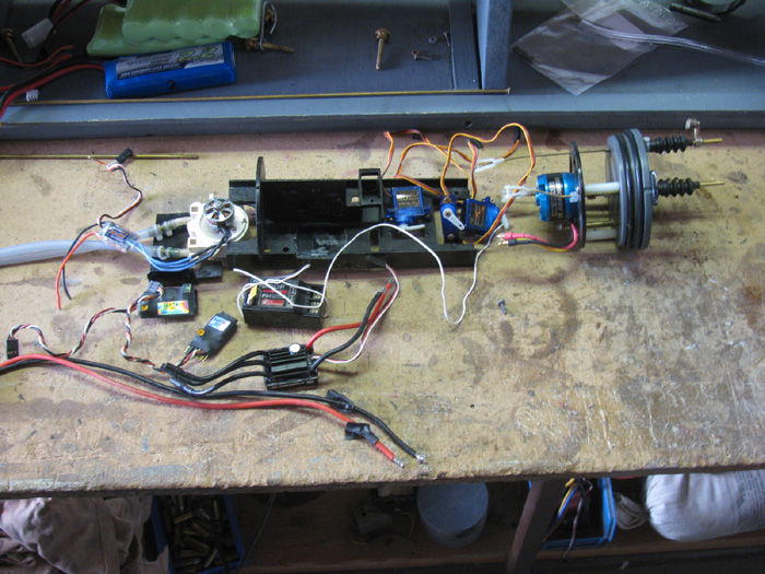
Laid out the parts that need to be placed on the tray.
3 Servos, Speed controller, Rx and Pitch controller
Going to be tight but there is a solution to raise the Rx above the
ESC and pitch controller.
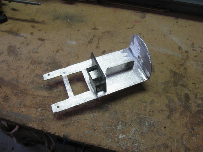
2 parts made.
A box to raise the sail servo up over the rudder and rear planes servos.
Actually took this from the original electronics tray.
It worked there and I do not see why it won't work here with a little
modification
Second part is an aluminum plate bent at 90 degrees to mount the Pitch
Controller on mounted on the tray next to the ballast tank lead screw shield.
(nothing is mounted yet)
Holes where drilled for the ballast tank screw shield.
Through the end plate and through the sail servo tray.
Shown with Pitch Controller bracket and with the Rx bracket set that
will be mounted to the end plate.
All the parts including the 2 "L" brackets that go on the motor frame.
Left to right is back to front of boat.
Now I need 10 bolts.
Will get more, tomorrow.
.
Oct 15th
Bought bolts to assemble the electronics tray. (3 mm)
Tray assembled.
I removed the motor frame from the end cap to make it easier to work
with and to drill holes for the tray brackets.
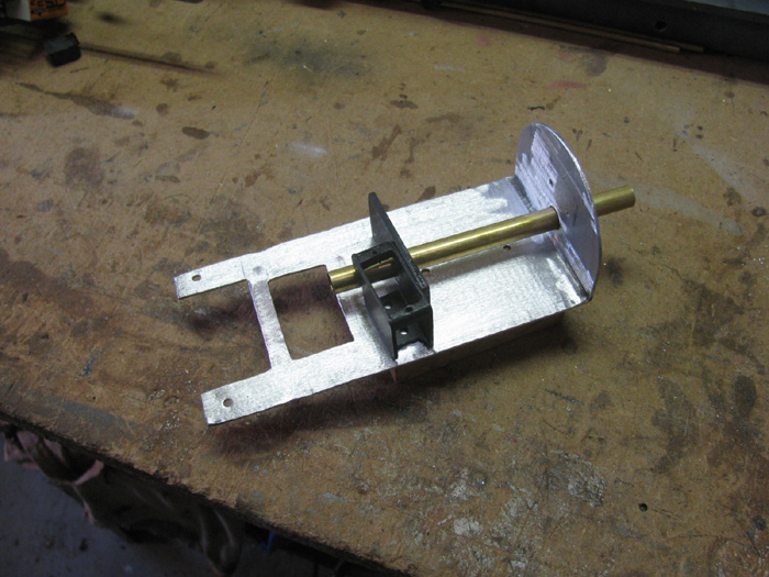
To mount the tray, I needed to line up the ballast tank screw brass
tube shield so it was centered.
Mounted the plastic servo tray, the pitch controller bracket (next
to the brass tube under the Rx bracket.
Made 2 tubing stand offs out of the tubes I made earlier that were treaded
in the ends.
Bent the second end over and drilled a hole for a bolt.
Was going to make 3 of these but the tray is ridged now.
I can always add it later.
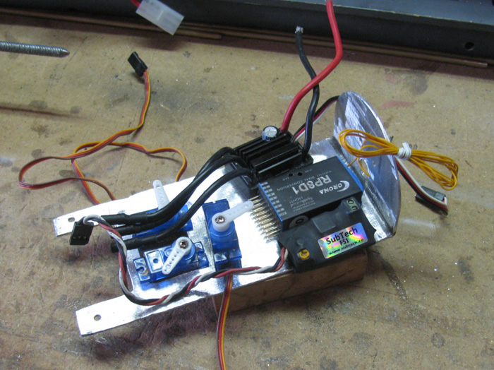
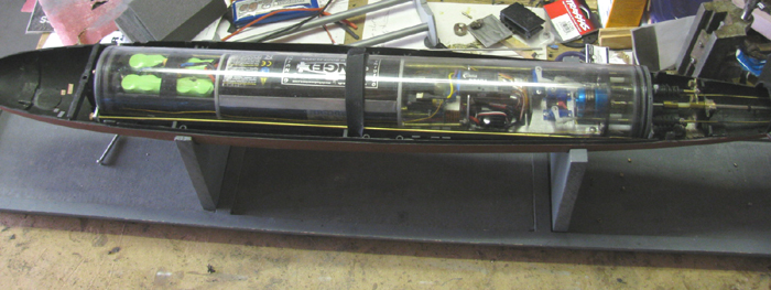
Here are all the electronics parts set in place.
3 servos, Rx and pitch controller.
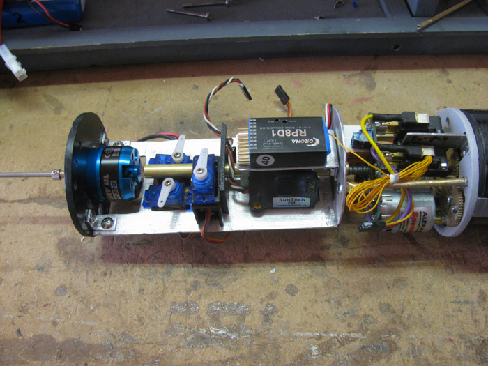
Other side shows the speed controller for the main motor.
Next I will disassemble everything and file and sand all the sharp edges
I missed as I went.
I test fit everything in to the wtc.
Found I have a tight spot.
The aluminum frame on the stand offs is too tall by about 3/16".
It goes in the wtc but it scrapes and requires force to insert.
I don't want anything that tight.
I will grind it down while I have it all apart. (the grinding will
be to the left of the Rx in this photo)
Also need to check that the Rx is not touching the wtc.
I have room to lower the Rx bracket about 1/4" if needed.
Oct 17th.
The electronics tray is assembled.
Wiring is also most complete.
Battery plug and power switch are needed.
Top
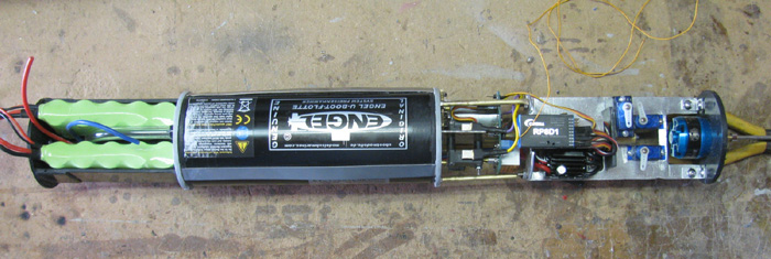
Left side
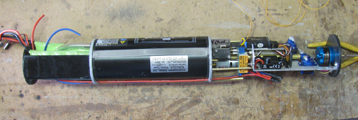
Bottom
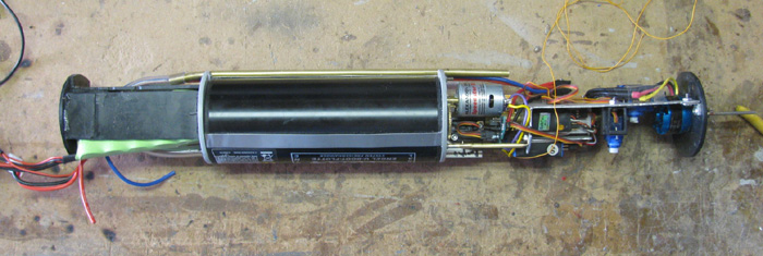
Right side
Oct 18th
Working with the electronics tray and ballast tank requires turning
it over and over.
The long antenna wire keeps getting in the way and tangling up.
Time to drill some very small holes and thread the antenna so it doesn't
move.
(orange wire going from motor frame to front of battery tray
and back)
Now it does not get tangled while working.
Scrape the paint off the lower hull so the new wtc stop can be put in
place.
It is right behind the "T" frame that joins the upper and lower hull
together.
Done.
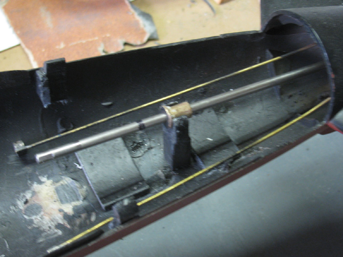
Working on the new location for the propeller shaft support.
The mark on the shaft is about where it will be cut once I know exactly
where the wtc ends.
Have to wait until I know if I am making a new front end cap.
There is a brace that goes across the hull.
It is in the vise after gluing two pieces of plastic together.
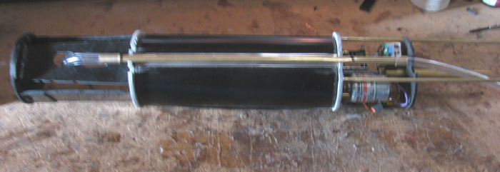
New electronics tray and ballast tank in the wtc, sitting in the lower
hull. no front cap at this time.
This afternoon, I replaced the stretched velcro strip that holds the
wtc in the lower hull.
Installed the wtc rear stop. (block under the propeller shaft)
Finished making the propeller shaft support.
Removed the tail cone bearing and cleaned it up.
Got all the silicone off of it and sanded it shinny again.
Installed the propeller shaft bearings.
Put the propeller shaft in most of the way and made sure it spins freely.
(I think it turns easier this time)

Stopped for today.
Will shorten the rudder and rear planes control rods tomorrow.
I was in town and got a few parts but did not find a terminal block
I liked.
Most where for house wiring and the blocks where huge.
Stopped a couple of places and one guy was trying his best to help.
He gave me a micro switch that would work but the amp rating is too
low. (3 amps is not enough and the wires coming off the switch are 22 gauge)
I can make brass lugs out of brass tubing that I solder on to the wires.
Flatten one end and bolt them together.
Cover with shrink tube.
(not there yet)
Going to try the 2 auto parts stores tomorrow for the terminal block.
I thought about removing some of the lead ballast weights.
Then I thought I should leave them because the wtc is longer and I
may need more weight.
Guess I will wait until trimming starts.
Oct 19
In the shop to work on shortening the control rods.
First thing was to pull the electronics tray out of the wtc to get to
the servos to put the inside control rods in place.
This required making some cuts in the sail servo tray to get the rod
past it without bending the brass tubing.
Carefully push the 1/8" brass tubing through the rubber bellows.
Bellows have very small holes on the end.
Put the electronics tray back in the wtc and cut to size the control
rods to the rudder and rear planes.
Unsolder the notched wheel collars of the cut end and solder on the
rods where cut.
Center the servos and center the rudders and planes.
Mark that location and get to soldering.
Will adjust after I get the speed controller and ballast system programed.
(coming soon)
Now the fun begins.
I made my sail planes working from the beginning.
I want the same now.
So I need to over come a small issue.
The wtc is 2" long and the stern end in very close tot he hull at this
point.
Before, I had about 1/4" to 5/155" to get the control rod through and
have 1" travel.
The old magnet assembly now holds the upper hull up about 1/4".
What to do?
The first parts I made required too much effort to connect the magnets.
(3 hands needed)
Thought about it and came up with this unit.
I removed the parts that attached the magnets to the wtc control rod.
It had a post sticking up to get the control rod up to clear the end
of the wtc.
This one is a "U" shape bracket on the control rod going forward to
the sail.
It goes around the rubber bellows and is level with the bellows.
The 2 magnets had to be move outward to clear during operation.
Then I needed to make a new bracket for the control rod coming out of
the wtc.
Made 3 all total and this one worked the best.
Took a large wheel collar (1/8") and drilled a hole 1/16" through it,
90 degrees from the Allen screw. (want the screw straight up for access)
Put a 1/16" brass rod through the hole and soldered both sides in the
wheel collar.
Drilled the rod by going through the wheel collar hole.
1 magnet goes on each end.
Currently they will still come off but will be secured after adjusting
with Tx.
The control rod has a small bend at the end cap.
This actually keeps the control rod level with the wtc side all the
way to the sail.
Had to modify the sail planes control rod to make it 2.25" longer and
fit he "U" shape magnet bracket.
The magnets are not fits in position. They will swivel a little for
self aligning.
The ones on the "U" bracket are fits only because they fit very tight
on the assembly. (I can manually move them if I have to)
I could use the original front end cap but I plane to make another one
tomorrow.
This cap is very simple to make.
It has no lip one one end.
The cap was made so it could slide all the way in to the wtc to adjust
the volume of the cylinder.
Found I didn't need it so there is an aluminum bracket screwed on to
the end that stops at the cylinder end.
The bracket is for the 2 pressure safety rods. (not in the photos but
on the table next to the stand)
This build is coming to the end.
2 drops of CA glue once I know where the magnet rod ends will be.
Adjust all controls.
Still looking for a power switch but I have decide there is an alternative.
Wire the main power to the rest of the electronics tray.
Oct 26th
In from the shop.
The pressure rods are complete.
Brass tubing and cable have been joined and set to the length needed.
The end cap is complete.
Pressure rod bracket on the front of the end cap has been make, shaped,
drilled for pressure rods and bonded to the end cap.
I need to go in to town so I may get back to this this afternoon.
Sort of waiting for the new switch to arrive, today or tomorrow.
I would like to get it mounted before I install the o-rings and assemble
the wtc.
Once assembled, I should only have to take an end cap off to charge
the batteries.
I will wait on the switch.
Then it is back to water testing and then on to trimming, I hope.
---------------------------
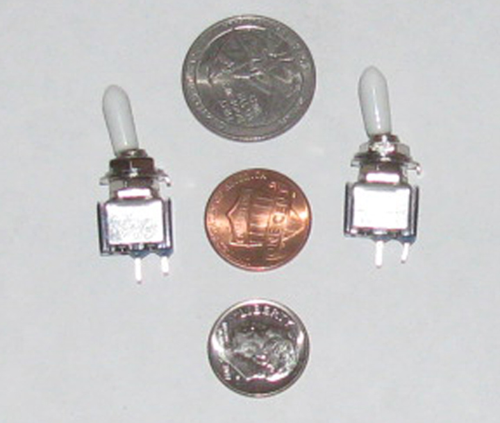
Oct 29th
I was at the post office this morning and I picked up the new
10 amp switches.
I can now build the plastic parts to hold the switch in place.
The problem was finding a small 10 amp switch that would fit in a 1/2"
space.
This looks like it will do nicely.
The switch bracket has been installed waiting for the glue to cure.
The wiring has been sorted out.
Looking from the front.
Batteries put in place.
Switch is in place.
Got the Tx so I could plug in the batteries.
Turned on Tx and then Rx.
Electronics tray did not come on.
Got the switch correct. (off)
Turned on the power switch.
Got the normal startup noise from the electronics.
Checked all the controls.
All good and correct.
Turned everything off.
Removed batteries.
Letting glues cure so they vapors do not frost the cylinder.
Then I will get photo with the cylinder slipped on.
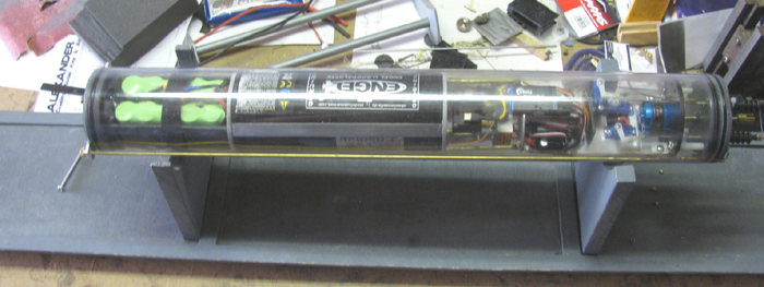
Oct 31st
Electronics tray slipped in to cylinder showing switch location.
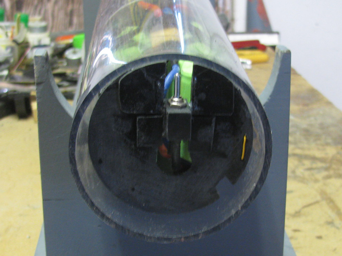
When the end cap is in place, the Shrader valve is inline with the switch.
I have a tool I made for the George Washington that works just fine
with the Skipjack.
1/16" brass rod with a loop on one end to hold on to and a 90 degree
hook on the other end that will go through the Shrader valve and pass the
switch toggle and when pulled forward turn on the switch.
Then to turn off, push the hook through and push on the switch until
off.
The shinny spot in front of the batteries is the switch and hook.
==================================
For many years I have been running submarines. (late 80)
When I run my boats all is good until I run at periscope depth and out
about 125' I loose site of the boat.
With the background sun light, hills and tree reflections, I can not
even see the wake produced from the mast.
At this point I have loose contact with my boat.
I work the rear planes or the sail planes to bring the boat up a few
inches to reacquire the boat.
Most of the time this works.
But then there are those times the boat must have gone deeper than
I thought and I have to ballast off some to bring the boat back up to where
I can see the top or more of the sail and start trimming all over again.
The part that makes me nervous is when I input planes to bring the boat
up to the surface and it does not happen.
Seconds go by and I get more nervous.
Then PANIC sets in and I empty the ballast tank more than half way
so the boat will pop up.
Lately I have been running in a lake which is probably 400' across
and length is .... I don't know. 3/4" of a mile if you go between the 3
wide areas.
Any way, while trying to relocate the boat it is moving along.
When I finally bring the boat to the surface, I find it is 100' or
more from where I lost it or it has turned in a slow circle and may be
coming at me or away from me.
While this is going on, I have to keep track of the other boats in the
water, 2 to 5 or more.
What I realized after several of these events, I noticed I can find
two of these boat rather quickly even when they are at periscope depth.
WHY?
Well, they run with white plastic antenna tubing out of the top of the
sail or tubing painted white.
It seems my silver periscopes and black antenna masts disappear in
the reflected background stuff.
So a test was called for.
My Akula II like most of my boats have removable masts.
The test would be to make a new mast about 2" taller than the tallest
mast on the boat.
Paint the lower section black and the top section white.
This gives me about 3" of white mast.
Last run at the lake. (past Saturday), I put the new mast on the boat.
I did in fact loose the boat twice.
But I reacquired it in short order, with a little up elevator.
I could see it out to 150' even with the sun light and background reflections.
I ran the boat for 3.15 minutes plus. In the water once and out of the
water once.
On my Skipjack which is being modified right now, I went out to the
shop and took my periscope mast and made a change to it.
This mast plugs in to a socket in the top of the sail but it has a thin
shaped 1/16" rods rod to look like a periscope.
I took and turned it over and dropped the periscope down in to the
socket.
It dropped all the way to the mast tube stop and was stable and tight.
I was using the periscope and the lower pin in to the socket.
Okay, that works.
I then added 4" to the bottom of the mast.
I did not use tubing the size of the mast but the size that slipped
in to the mast.
I tested before building but the small tubing dropped in to the socket
and went almost to the bottom of the sail.
I used the smaller tubing to get the height I wanted and then I added
a piece or the mast size tubing to bring the mast up.
I gained about 1" it total exposed height.
The mast main section is now painted gray.
The periscope is painted silver.
The other end is painted white.
How this will work.
While the boat is on it's work and display stand, I put the mast in
with the periscope up.
As I put the boat in the water, I can lift the mast out and turn it
over giving me the white mast at about 3" taller.
This will make it easier to track when submerged to periscope depth.
A simple fix for a big visual problem I was having.
I could have just as easily made a second taller mast that was white
and gray and just put the periscope mast on the display stand when I run
the boat.
May do that yet.
But for now, all is good.
=================
Mike Dory and Will Oudmayer run White masts.
Thanks guys, this has helped a lot!
=================
Nov 2nd
Trimming.
Tx on.
Rx on.
Controls checked.
Schrader Valve cap on.
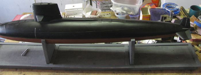
Cylinder checked in water for leaks.
Upper hull in place.
In to the water it goes.
Bow immediately goes to the bottom.
Stern stays above the surface.
Quick check of controls.
Remove boat from the water.
Remove upper hull.
Remove Schrader Valve cap.
Turn of Rx.
Turn off Tx.
Take the lower hull out to the shop bench.
Disconnect control rods (2)
Remove velcro stray.
Lift cylinder out of lower hull.
Now the work begins.
Remove the lead ballast weights.
They are siliconed in so they can be removed.
This will take 2 flat blade screw drivers.
Slowly work 1 screw driver under an edge of the ballast block.
Push the second screw driver under the block and lift slightly.
Keep doing this without breaking through the hull plastic.
I removed 6 blocks from the lower hull.
All forward of the center of the boat.
Left 1 little block in the stern under the propeller shaft.
Back in to the house to do another water check.
Have several ballast block to place on the hull using rubber bands.
Place 1 large block under the hull stern line cut.
In to the water.
The stern is still high but better.
The bow is about 1/2" low but not on the bottom.
Added another large block under the stern with the first block.
A little closer to getting down to the waterline.
I can get the boat to the water line with a small block in the stern
about 4" forward of the 2 big blocks.
However there is a bigger problem to deal with.
The new cylinder and equipment is heavier than the original system.
The boat is near waterline trim but the boat rolls over on it's side
about 80 degrees.
There is no way to shift the weight in the wtc.
The batteries are much bigger and heavier than the original battery.
So, to get more lead ballast weight in the bottom of the boat, I will
need to over come the added lead weight with foam.
(EEEK foam)
It's not that bad, I have 1 boat with lots of foam in it because the
boat is small and the cylinder would never float the boat on it's own.
Dig out my blue foam bag.
Find some blocks that will fit the space I plan to use.
80 grit sand paper and a razor saw.
Hack out some pieces and sand them to fit the hull curve.
Sand the edges smooth and clean.
Trial fit as I go.
I have made 2 blocks of foam for the bow. (think it may need a 3rd)
A smaller 1 for the stern.
I had to glue 2 blocks together to get it big enough to fill the bow
space.
Will let it cure.
Then I will test the block by attaching the lead weights to the foam
blocks and see if there is enough foam to float the lead.
If not, more foam.
If it does then I can water test and see if I need more lead.
Going to be a busy day, here.
Nov 7th
I have been updating the build on SubPirates but I thought I should
show you the foam needed.
The 3 pieces in the bow are 1.125" thick. From the center line seam
to within 1/8" of the waterline.
All foam will be underwater when on the surface.
The strips a long the sides are 3/8" thick and 1.125" tall.
Same as the bow.
From the center line on the hull to within 1/8" of the waterline.
The piston system is much heavier than the balloon system.
Once the foam was put in, to counter the weight, the length that I
cut the piston will go from surface to bottom with about 10% left on the
piston on the full side.
If I need more stability, I can add more foam and more weight but I
won't know until I run the boat in the lake to see how it reacts in a turn.
Foam blocks are shaped to fit the curve of the hull as well.
================================
================================
Skipjack Modification #7 -Parts List.
Price on parts from Engel's are converted from pounds and includes their
VAT tax.
In USA we don't pay VAT but there is Customs fee.
|
Description |
Supplier & web site |
cost |
| 1. |
WTC - 24" long 3.5" outside diameter |
McMasters-Carr
Clear Polycarbonate
tube
Part number 8585K44 |
$39.00 |
| 2. |
Piston Ballast tank |
Engel's
Piston
Tank EA750-12V
Modified to 600 ml |
$275.00 |
| 3. |
Ballast Tank Controller |
Engel's
CTS2.2
12V |
$84.00 |
| 4. |
Ballast Tank control |
Engel's
Hall's
Sensor
#1585-H05S |
$19.70 |
| 5. |
Main Propeller motor |
Engel's
Mercury
BL Outrunner C35-30-300
#3706 |
$39.25 |
| 6. |
Main Motor Speed Controller |
Engel's
Sub_Commander
BL-30
#3750 |
$41.90 |
| 7. |
Pitch Controller |
Engel's
Pitch
Controller SPC2
Works correctly in forward/reverse and has Fail safe built in.
(I am using a SubTech ALS Auto Leveler - because I have several) |
$77.00 |
| 8. |
Receiver |
Your choice
4 channels or 5 to include sail planes. |
$00.00 |
| 9. |
3 Servos |
Your Choice
I use HXT900 |
$3.05 |
| 10. |
12" brass tubing |
From ?
For ballast tank inlet/outlet. |
$00.00 |
| 11. |
3' rubber hose |
From ?
ballast tank hose |
$00.00 |
| 12. |
1 micro power switch |
From ? |
$00.00 |
| 13. |
Push rod seals 2 or 3 as needed |
Rubber boot seals. |
$00.00 |
| 14. |
1 Main shaft seal |
Cup seal
O-ring Store |
$00.00 |
| 15. |
End cap o-rings |
O-ring Store
3 1/4"ID X 3 1/2"OD X 1/8"CS
Buna-N
O-Rings 70 Duro (NBR) |
$00.14 |
I will admit that the parts are expensive.
As noted, this is my 7th modification to this boat.
I have been trying various system in this boat and I will say, this
system is by far the best system I have every run.
It is worth every penny.
I have tried vacuum systems, pressure systems, water pump systems, snorkel
systems and Compressed air systems.
The secret to this is the Hall's Sensor.
This little magnetic devise when setup correctly, counts the number
of turns on the piston lead screw.
Well actually, it counts every 1/4 turn of the thread lead screw.
If your transmitter has a very sensitive knob control or slider control,
your will get more out of the Hall's Sensor.
When I setup my Akula II, I followed the instructions.
German to English translation seems to miss a step in the setup.
It worked.
Then Will ask me why I setup the Halls like I did.
He offered to check out the system and reset the Ballast Tank controller
and Hall's.
My Tx was making about 3 to 4 turns for every click.
After will reset the thing, I could see 1/2 turns per click.
Then I bought one of Will's control pots and I could see 1/4 turns
on the gear.
Around the lake this little device has been dubbed, Will's "Dial a Depth".
I am still learning how to use this new control with the other controls.
But even I can run for an hour with just the periscope above the surface,
1/2" to 2".
Then I start messing with the other controls to see what effect they
have and then it takes quite a while to get the boat back to periscope
trim.
I swear, if I just think about touching the depth control knob, the
boat goes up or down 3" or more.
At this point I usually have to surface the boat to find it and start
over at trimming it.
Feb 16th
Repair on the Skipjack ballast tank system.
Boat on the stand.
Upper hull removed.
Cylinder out of the hull and sitting on the stand.
Electronics tray out of the cylinder sitting on the stand.
The electronics tray separated from the ballast tank system. (3 nuts.
2 bolts)
Unsolder power wires.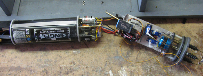
Ballast system parts removed from the tank frame.
Screws holding tank together removed.
Turn ballast tank piston screw and remove tank end.
(screws holding tank motor on are in side the tank)
Ballast tank motor replaced.
Tank electronic system reinstalled.
Electronics tray attached to the ballast system.
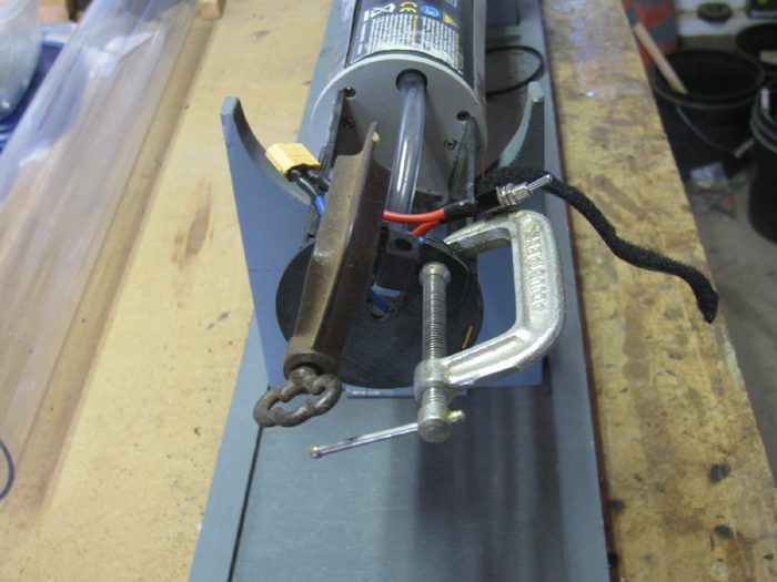
Still need to solder the power wires together.
The Clamp is holding the main motor esc as the silicone cures.
The two sided tape was not doing the job.
Testing the system tomorrow.
All testing was good.
--------------------
Feb 23rd
There was an informal gathering of SubRonLA.
4 captains and 6 or 7 submarines and 1 sailboat.
Put the Skipjack in the water and did the 2 static dive next to the
shore to get the air out of the ballast piston.
Surfaced the boat and made a few circles to check controls.
All good.
Came in to the end of the dock, we have an 8' square dock the park provided
for us. and did a static dive to the bottom in stages.
Down to decks awash.
Down to the bottom of the sail.
Down to the sail planes.
All good and level.
Down to the top of the sail.
Well that is interesting.
With the top of the sail about 1/8" to 1/4" above the water surface,
the stern starts to drop.
I continued to drop until the boat was sitting at about 10 degrees
stern low.
Continued static dive to the bottom.
About 4' or 5'.
Came up about 2' and hovered.
Still stern low.
Up to periscope depth.
Still stern low.
Put on forward power and the stern came up to level with the use of
rear
planes.
Brought the boat to the shore and out of the water for a quick look
at the wtc for leaks.
Opened up the hull and I see no water in the cylinder.
Back in the water.
Ran for about 2 hours with about 1.75 of that at periscope depth except
when I lost sight of the boat diving.
The putting full rise on the sail planes it would come up and usually
about 100' from where I last saw it and going in a different direction.
Came in and out of the water.
Opened the hull and checked for water.
None.
This was a necessary out of the water as I needed some personal time.
Third time in the water.
Still the same stern down issue but with a little forward movement
the boat came level.
Ran another 1.5 hour, mostly submerged.
Control of the boat is very precise. Some times I think I can look at
the control an the boat does it.
Last time out of the water, open the hull and look for leaks.
Again, none.
It was a good day.
While running some of the conversation was about fixing the issues I
had.
1. The stern dropping.
2. The bow has a low surfaced waterline. 1/4" low.
3. The boat over all is too heavy. I have 40% negative ballast on the
control knob.
Possible fixes.
1. Move the small ballast weight that is all the way aft. forward about
1/2".
I did this and I used a half size weight.
2. I added a small foam block in the bow below the water line.
In the photo it is the block with the arrow on it.
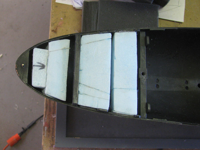
3. Add foam above the water line near the middle of the boat.
Pink foam under the sail planes control rod.
This may be in the wrong place but I will test it
before I change it.
It may be too high above the waterline. (will see).
It many not be enough foam. (will see)
I have 2 weeks to work on this trim issue.
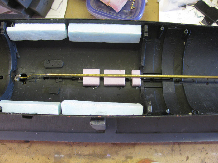
Feb 25th
Cut a groove in the 3 foam block I put in yesterday for the sail planes
control rod to move.
I added more foam just above the waterline. (pink blocks)
Next, I will have to get the boat in the water to start working on
trim.
Feb 26th
Today there will be trimming in the water.
#1 In the water, I did the check list stuff.
Fill the ballast piston. The boat went to
the bottom.
Empty ballast tank to get all the air out.
Did this 3 times to make sure all the air
is out.
#2 Surface the boat completely emptying the ballast piston.
Observe the waterline.
Stern is good.
Bow is still low. ? ?
#3 Submerge the boat to the deck sail intersection.
Boat sits level. Good.
#4 Submerge the boat to the top of the sail.
There it is.
The stern drops about 3".
Now I have rubber band around the hull so
I can place foam blocks on top of the hull.
Tried several different size blocks until
I found one that was close to holding the stern level.
Out of the water and out to the shop.
Open the hull and mark where the foam should go.
Look over the bow to find a place to add more foam to get the bow up
to waterline.
It looks like I can put 2 blocks just behind the frame that holds the
upper and lower hulls together.
Measured the space.
I can get 2 blocks about 7/8"x1"x1.25".
One on each side of the Schrader valve.
Cut 2 blocks and shaped them to fit the hull curve and around the frame
guide blocks.
I also checked on how much control input is required to submerge the
boat to the bottom.
Before starting, I had about 40% negative control
Far too much.
Now it looks like I have about 10% negative control.
The additional 2 foam blocks with use up part of this 10%.
If I can get the boat's level, surfaced and submerged, I can add weight
if I should use up all the negative control and not get to the bottom.
The weight would be added near the center of the hull.
I am talking less than 1/2 ounce weight.
Currently letting the silicone on the foam blocks cure before I get
it back in the water.
I need to put the foam block in the stern while I have the boat all
apart.
===================
I have 2 bathrooms in the house so I can leave 1 bathtub full of water
while I do the trimming.
===================
Water testing again.
The size of the foam blocks brought the boat up to waterline and I have
negative ballast to bottom the boat.
I now have most of the control for the ballast tank.
I have about 10% left when the boat does to the bottom.
This is much better than before.
I still have the stern dropping issue.
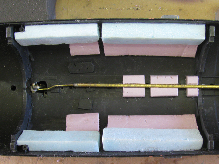
I need to move foam from the center of the boat towards the stern.
I removed the 3 foam blocks that were middle of the hull and above the
waterline.
I also removed 2 blocks on the sides which were forward of middle of
the boat.
Going to move these towards the stern.
I am not going put the small block back in for now.
I shaped a new block to fit the curve of the hull which will be placed
over the control rods coming out the back of the cylinder.
This location is below the waterline by 1/4".
The silicone for these blocks needs to cure.
Tomorrow I will be back to trimming.
Mar 17th
After running at the lake for 3 hours yesterday, I am back in the shop
moving ballast weights around to fix the trim issues I still have.
The boat ran perfectly submerged but there are issues of stern high
surfaced.
I removed two forward ballast weights.
There was no place to move the front weight without going way to fat
back.
So removing the second weigh, I was able to put the 2 weights side
by side.
I gapped them with plastic shims to get 3/8" between the weight for
water running.
Here are the two weights in their new place.
The top weight was left of the hull frame originally.
Tomorrow it is back to trimming in the water.
=
Parts made for Mike.
Magntic coupling.
|