| This modification will be to change the bow Z cut to a centerline cut.
I have 3 boats with Z cut hulls and I have come to not like them.
My method of slipping them together works well but at times, getting
the bigger boats to line up the full length of the hull becomes a frustrating
proposition.
So, I have decided to cut the lower bow off the upper hull and start
over in fitting the upper and lower hull halves together.
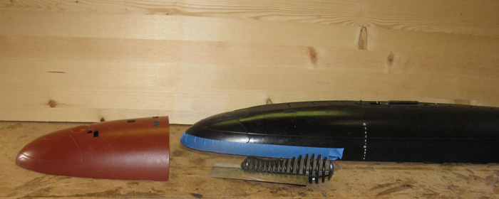
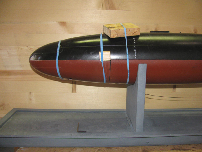
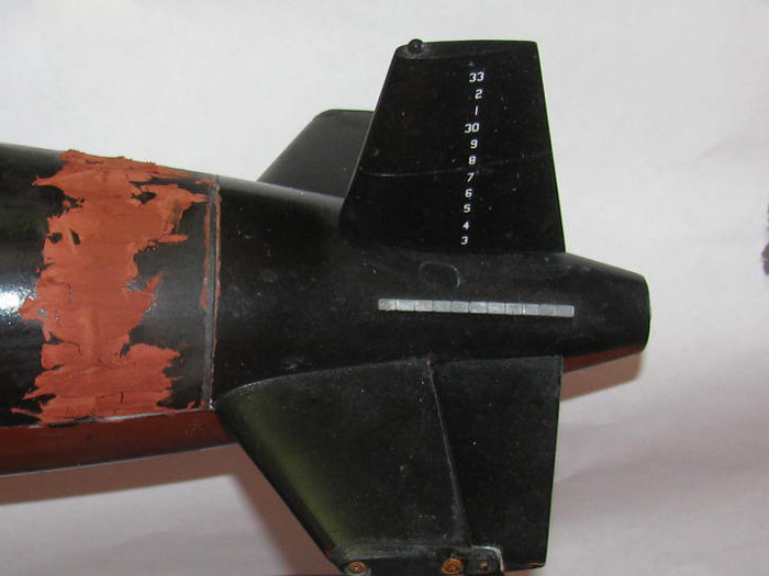
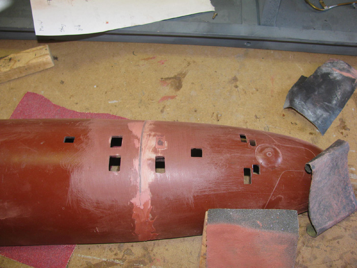
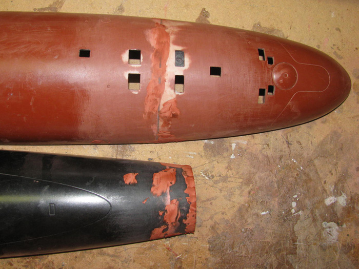
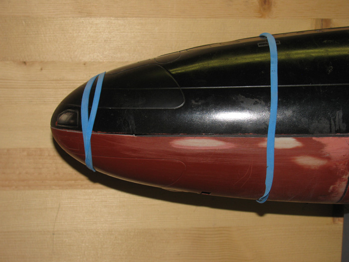
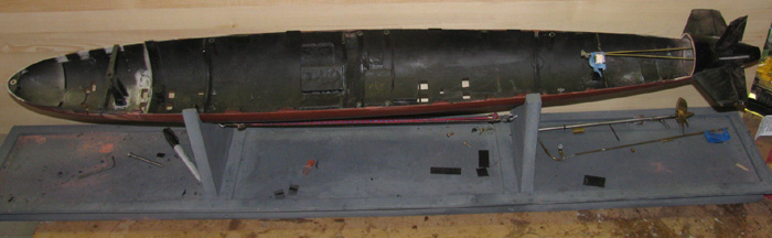
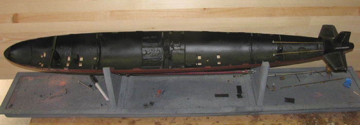
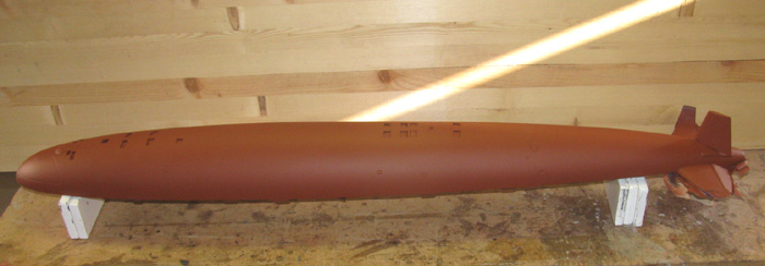
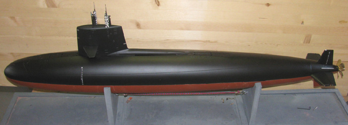
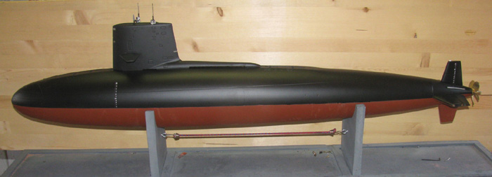
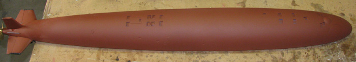
Here is the boat before I start cutting.
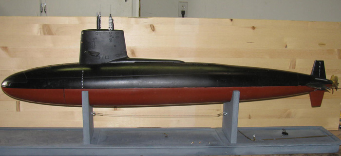
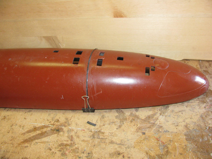
A look at the Z cut.
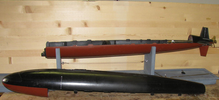
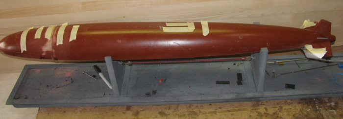
The upper hull lower bow will be removed.
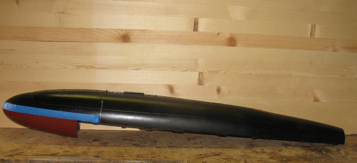
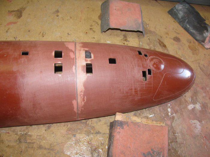
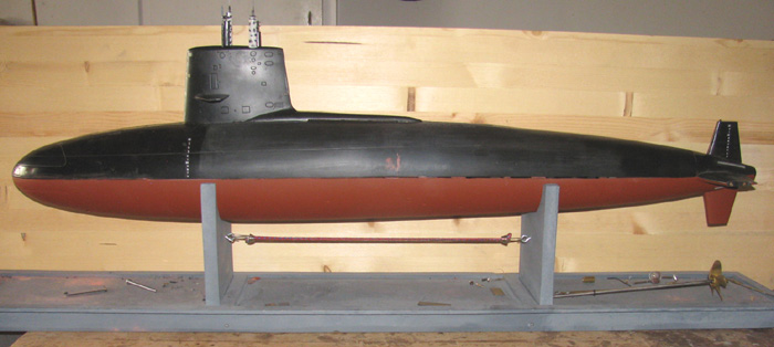
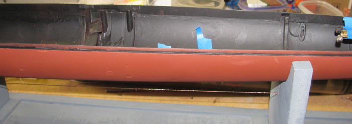
Cut line taped to guide the saw.
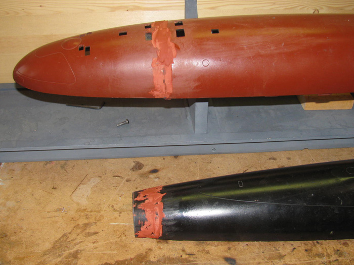
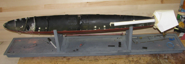
Cut made and lower bow separated from upper.
An other look of the separation.
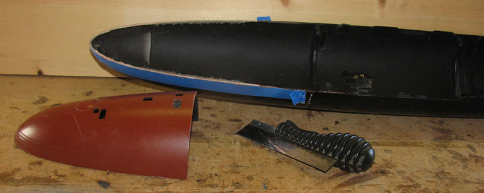
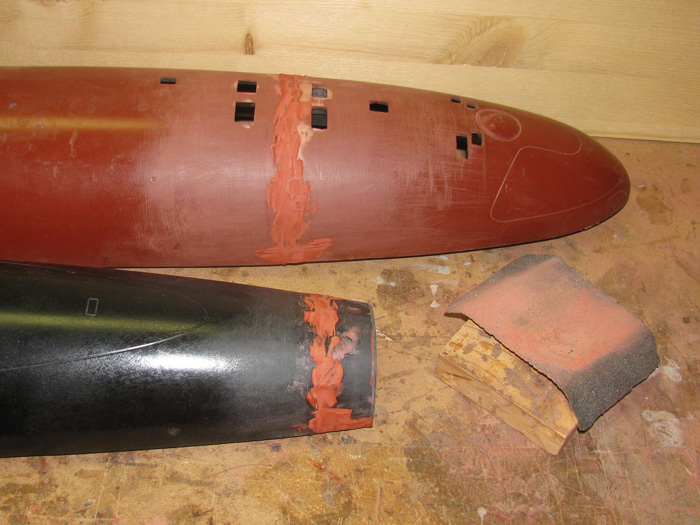
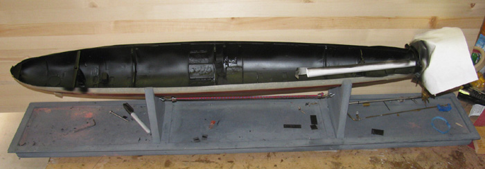
What are we looking at, here.
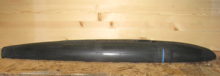
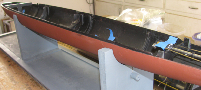
The upper hull, rear Z cut has been cemented to together.
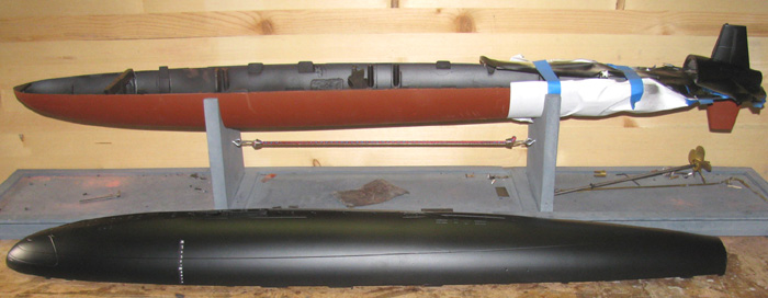
The lower bow has been cemented to the lower hull.
Using the upper and lower hull to keep every thing aligned.
The center line cut goes to 1/8" in front of rear planes.
The right side of the tape is my new cut line.
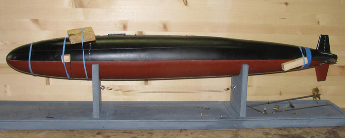
The front and back upper hull are now one piece again.
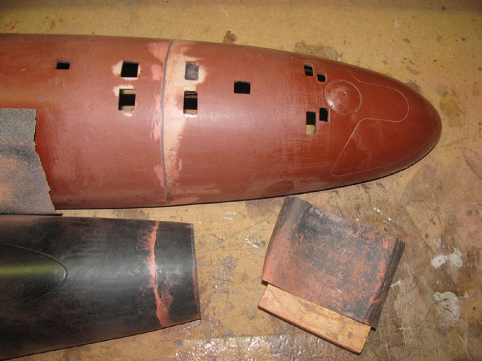
Rubber band and wooden blocks are keeping the upper and lower hull
pieces straight and aligned.
There is a gap at the old Z cut that will get fixed later.
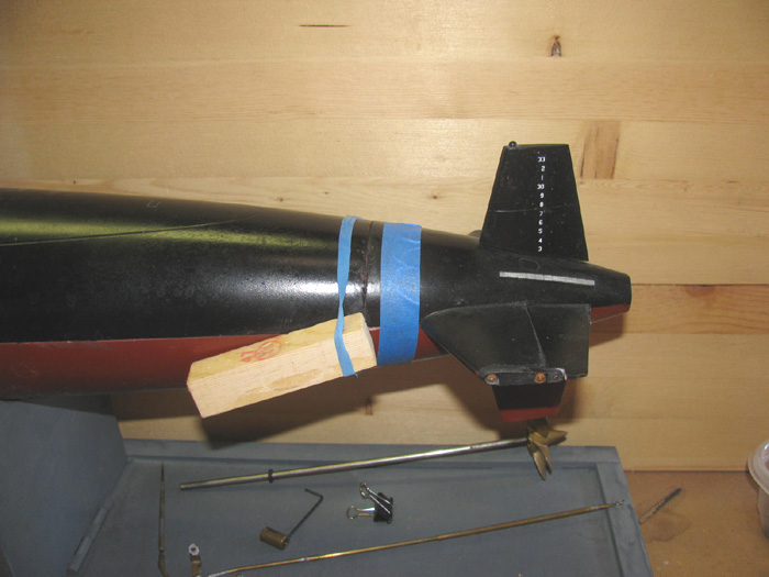
Turns out I could use the bolt that goes up through one of the flood
holes that kept the upper and lower halves together when running.
Made it easy to adjust the length and pull pressure on the joint after
applying cement.
Rubber bands to keep things aligned and wood blocks for more tension
on the rubber bands.
I will need to fill the Z cut gap on the bottom hull as well.
Cement has set over night.
Time to cut the upper hull loose from the bottom hull.
Having lined up the upper and lower hull, there is a small gap between
the main hull and the bow section.
Using a small square edged file I filed the groove wider and square.
There is a strip of plastic on the inside of the hull that join the
bow to the hull.
I filed down to the strip.
I cut a 1/8" wide by 1/16" sheet plastic strip.
Cleaned up the edges of the strip and fitted it to the groove I just
made.
Once I knew it would fit all the way around the hull joint, I started
on one side with plastic cement, bonding about 1" at a time and holding
until it held itself.
Did this until I was all the way around the joint.
I thought this to be a better fix than using glaze to fill the gap.
There will still be glaze but not very much.
Filed down the plastic spacers and sanded them flush with the hull.
Cleaned it off and glazed over the joints.
Checking the top hull fit to the lower hull.
Looks good.
I can now glaze the rear most spacer after the rest of it cures.
I will remove the top hull from the lower hull to do this.
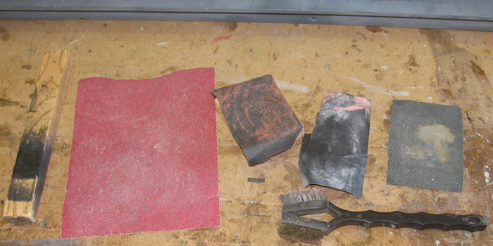
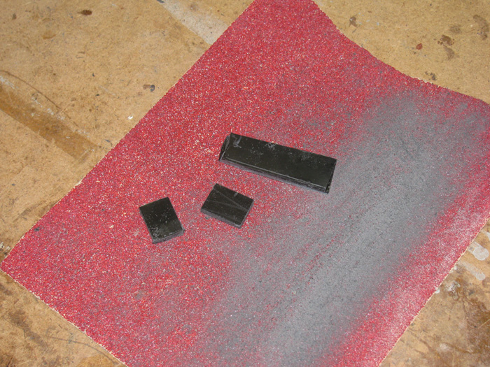
Gathered the needed tools to sand down the glaze.
Sand paper and wooden blocks.
Left to right.
.75"x1.25"x7" block
80 grit sand paper (did not use this one)
200 grit wet/dry sand paper
200 grit wet/dry worn out sand paper (did not use this)
80 grit wet/dry sand paper
Double steel/brass wire brush
2"x2.5" wooden block (not in this photo)
Using the 80 grit wet/dry sand paper, I knocked down the high glaze
spots.
I did not clean off the paper as I went.
I left it loaded up to reduce the cutting.
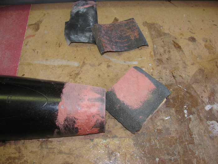
Here the joint has been sanded with the 220 wet/dry sand paper.
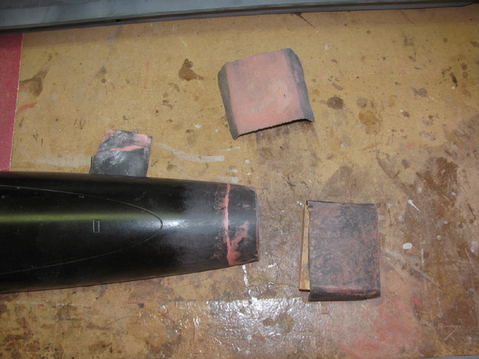
Same process on bow joint.
80 grit wet/dry.
After the 220 wet/dry sand paper.
There are small pin holes that will require and thin coat of glaze to
cover.
Glazing done and hull halves curing.
So far, I am real happy with the progress.
Ready to sand second glazing.
Sanding complete.
Still some small imperfections and the rear spacer needs to be glazed
on the stern.
What I hope is the last application of glazes on these parts.
While I was at it, I filled some very small dings on the hull,
5 spots that were there when I painted it last time.
Sanding after third glazing completed.
The center line gap show here but with a slight pressure on the top
of the hull, it closed up tight.
The top hull is just sitting there with no holding bolt.
Making a bracket to hold the upper hull to the lower hull.
I started by cutting sheet plastic strips.
1/2" wide. (sheet is 1/16" thick)
The horizontal pieces are alternated with the vertical piece in overlapping.
(like shuffling cards)
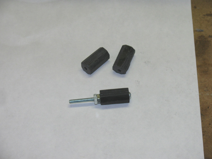
applied cement and placed in the small vise to keep pressure on the
parts over night.
The bottom bracket has 4 pieces cut in half before assembling.
These are in the center where the bolt goes through.
I did this ti have a good guide for drilling the hole for the bolt.
Only the bottom bracket is drilled all the way through.
The top bracket has a smaller hole, drilled about 3/4" in to the bracket
and then I threaded the hole.
2 brackets and stainless bolt.
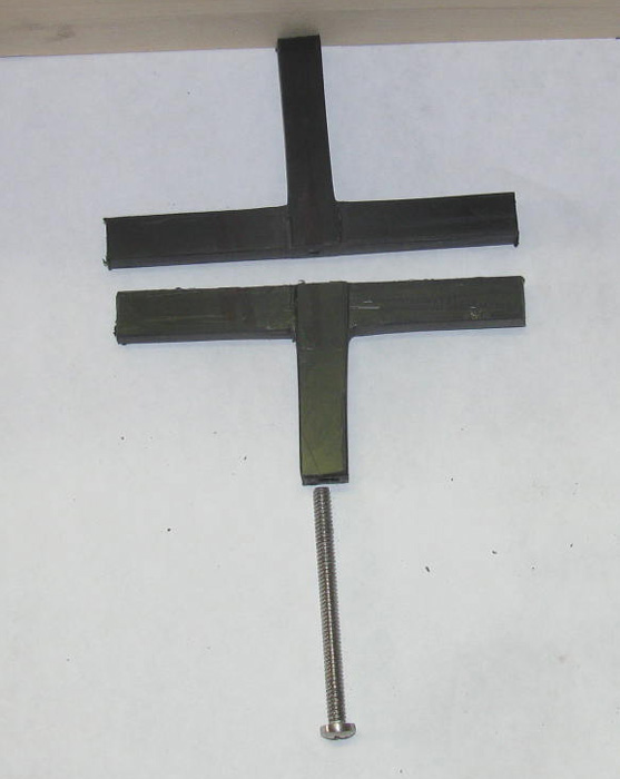
Bolt inserted and started.
Bolt tighten to snug contact. (don't want to strip the threads)
Brackets finished size is 7/16" wide by 3/8" thick.
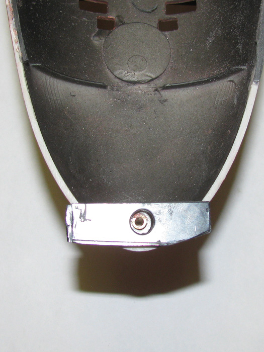
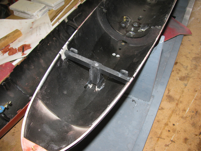
Bracket sitting in hull for look.
Shaping and adjusting height still needs to be done.
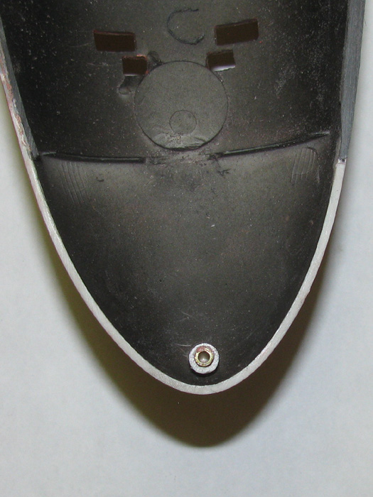
Here you can see the lower bracket sits over the center forward ballast
tank flood port.
The bracket will be raise about 3/8" using 2 pieces of sheet plastic
on each side of the bracket.
The flood port will not be covered and functional.
I have not decided which bracket will stand above the center line as
a guide to align the hull halves, yet.
But I would like the lower bracket standing tall so I can see it when
putting the top hull on.
The top bracket measure to be right under the forwards ballast tank
vents.
I will probably stand the bracket up on plastic pieces so the vents
continue to work.
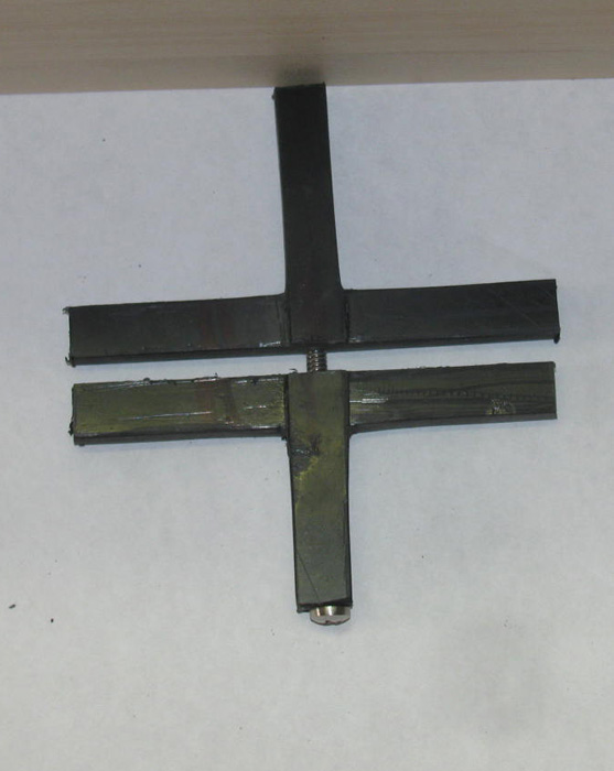
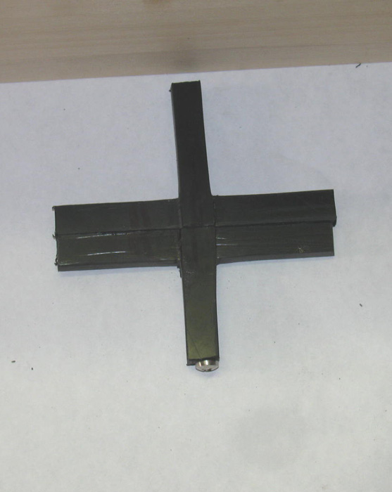
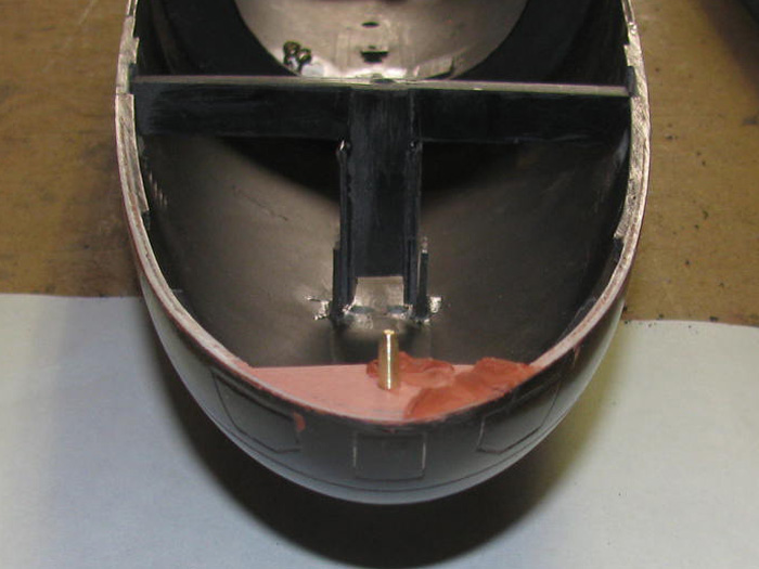
The bow connection "T" has been squared up and fitted.
The bolt is now centered in eh base piece.
The top connector is now square with the bottom.
Cutting the top stand off pieces.
This is to allow air and water to go through the forward vents.
Stand off pieces cemented and clamped in the small vise.
I cemented 3 layers of sheet plastic together.
Then I shaped the part to fit the bow curve.
Drilled a hole through the pieced to align with the upper hull pin
socket.
Drilled the holes 1/8" to accept a 1/8" brass rod pin.
The tubing goes through the part and in to the hull socket.
The part was bonded to the hull with medium CA so I would have some
time to make sure the tubing was vertical to the hull in both length and
beam.
The 3 pieces of sheet plastic fit but was slightly lower tan the hull
sides.
I used glaze to bring the part surface up tot he hull line.
I grease the tubing above the hole in the part so I can get it out.
(hopefully)
Sanded the bow socket piece.
Filled a couple of low spots.
Brass alignment pin satin place to look for square.
The pin is a little tall here. (I did not push it all the way in the
hole)
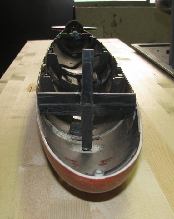
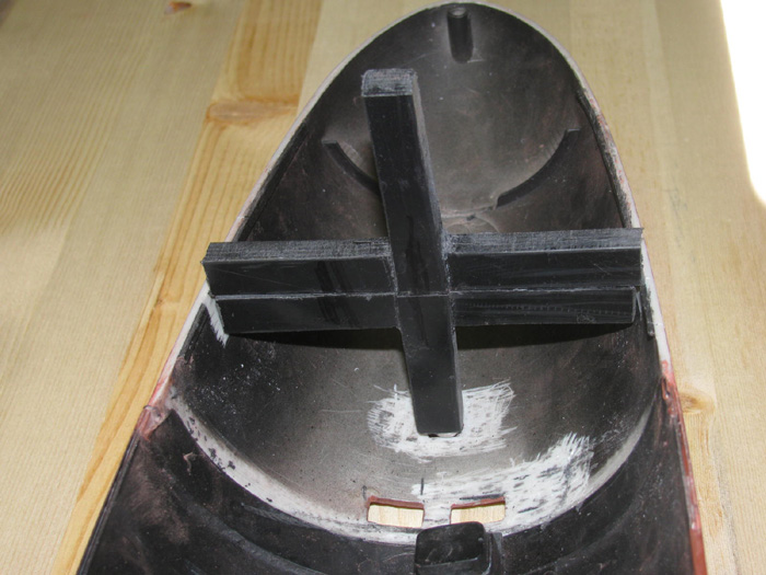
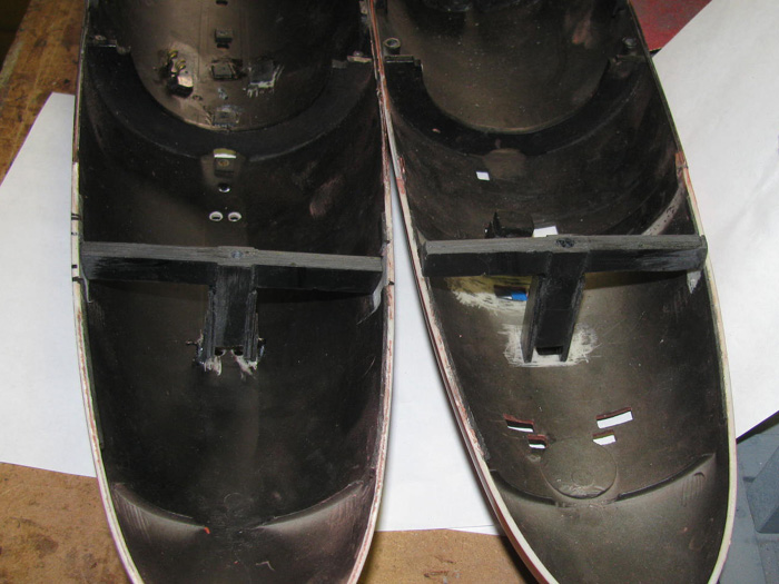
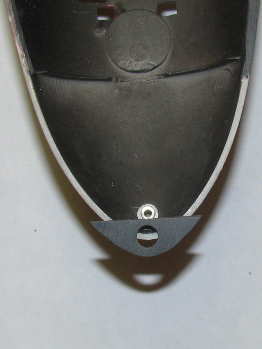
Both the top and bottom T brackets sized and sitting in place to check
measure locations.
Once the final sanding of the bow pin bracket is complete, I will work
on mounting the T brackets.
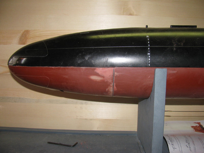
Here is the plastic piece bonded the hull.
It goes from the splice of the bow to the lower hull to about 2" from
the front of the bow.
Where the forward white line from sanding shows up.
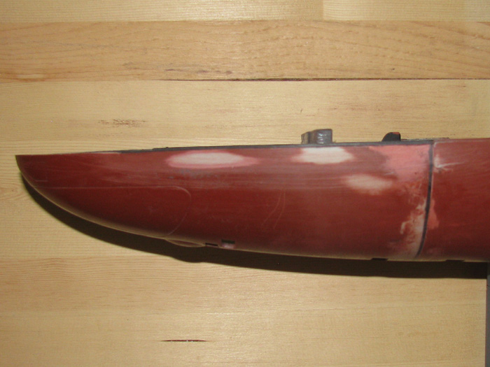
Checking the gap.
Still need to take a little more off from between the two large sand
marks forward to the little white line.
I am holding the bow closed.
There is still a small gap near the front.
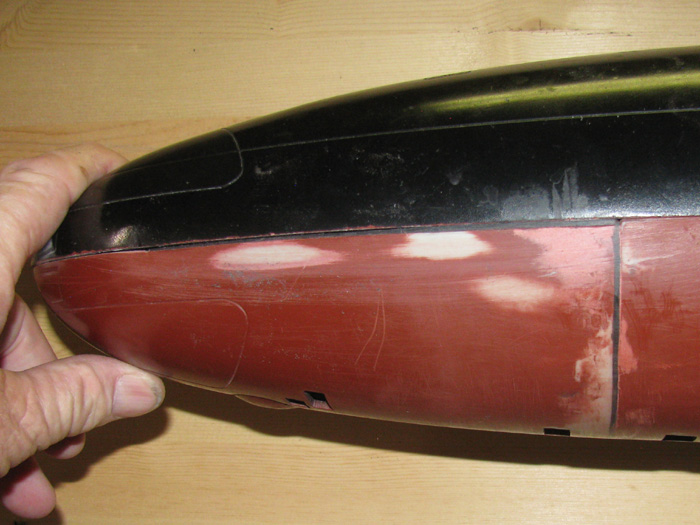
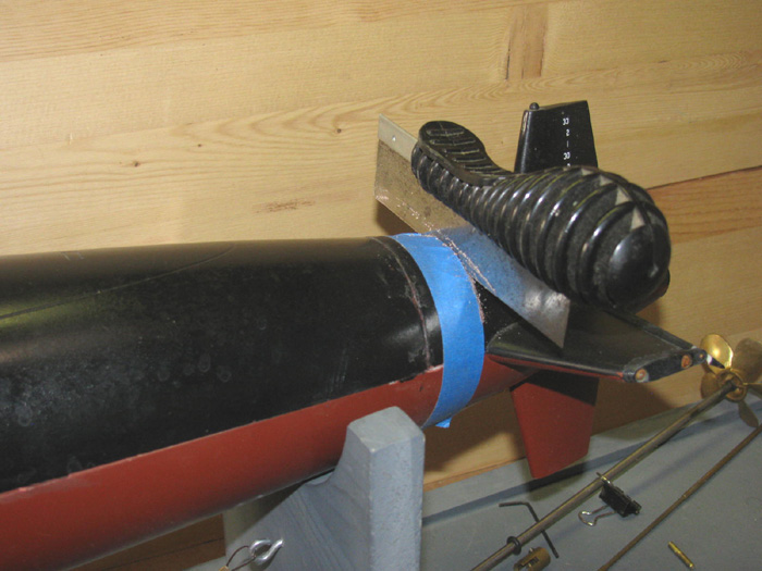
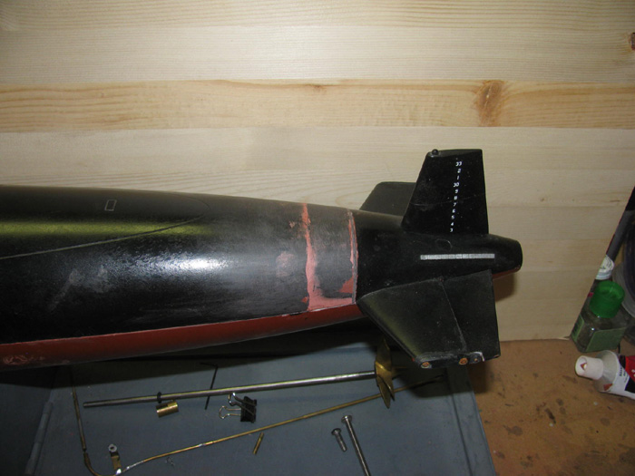
How about the tail cone joint.
You can see the black spacer I added and the cut is to the right side
of it.
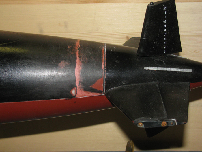
8/28/17 @ 9:15am
Back in the shop.
Making plastic parts.
Bow pin socket support.
A couple of hull alignment tabs.
Here the pin socket has been set in medium CA glue. (gives me a few
seconds to fit and move the parts.)
With socket sitting in CA glue, the upper hull is put in place with
the bow pin in the socket.
Rubber bands to keep hull joint tight and pushed back against the tail
cone cut.
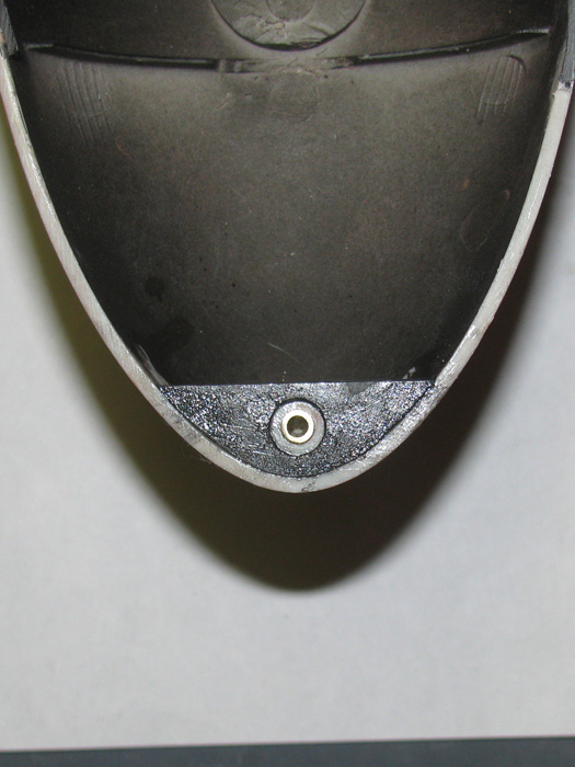
Now that the CA has cured, I am going to shape the bow socket support
piece.
Took about 10 minutes to shape.
Fits the bow curve and there is a bevel on the front edge to match
the hull shape.
Removed all the paint from the hull and plastic pin socket post so the
cement would bond.
Cement on both parts and the part put in place.
Made sure the support was flush with the hull center line.
Made the 2 tabs that go on the upper hull T bracket.
When the hull halves are place on each other, these 2 tabs will hold
the hulls apart until they are pushed against the tail cone cut and the
bow pin is over the socket.
Then the upper hull will drop own in to position ready for the connection
bolt.
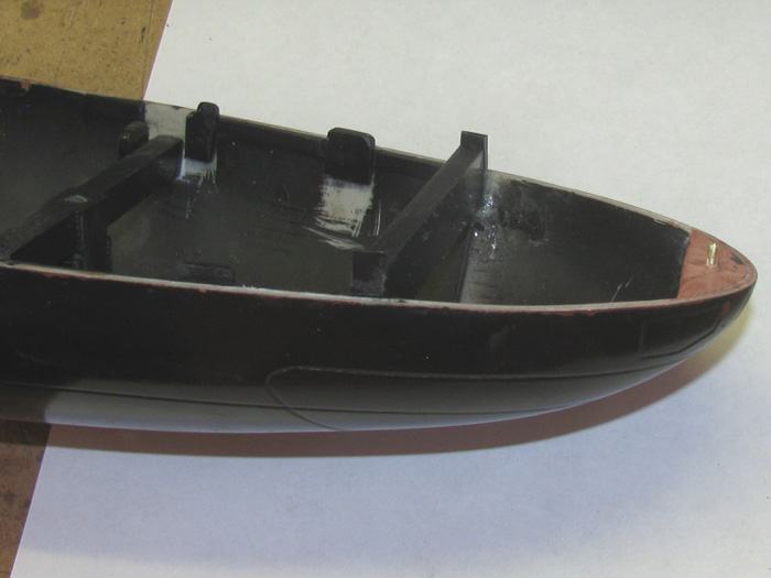
Fitting the upper hull to the lower hull.
I have installed all the plastic tabs I need. (I hope)
I have come across an issue at the bow.
With the upper and lower hull halves in place, the bow does not match
top to bottom.
The top measurement is good.
The lower hull measurement is narrow.
I thought about using plastic tabs but the plastic hull moves on both
pieces.
The top squeezes in and bottom spreads out.
Looking down the center line, this makes a con caved area.
That will not do.
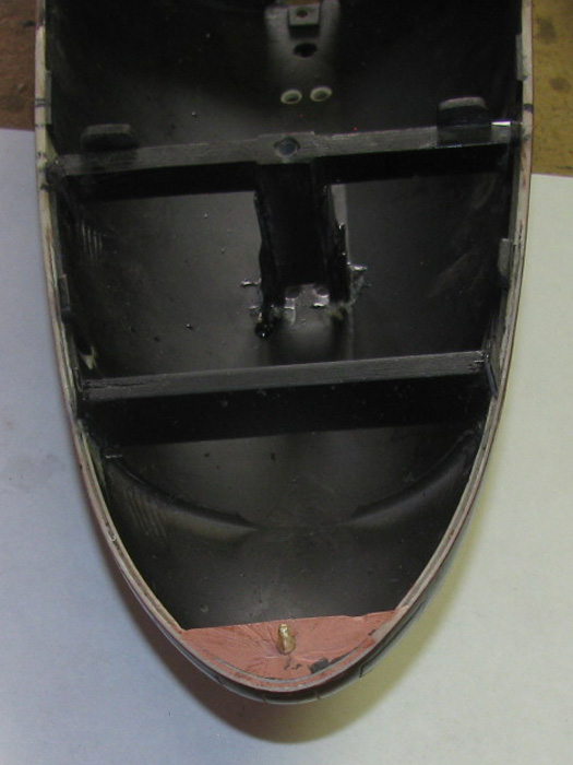
My solution is to make a pieces of plastic that will fit exactly in
the upper hull holding it at it's current width.
Make the piece tall enough to go in tot he lower hull and spread the
sides out to match the upper hull.
I cemented 4 pieces of sheet plastic together to give it strength. (1/4"
thick and 7/16" tall.
Shape to fit upper hull.
Cement bond the ends in place using a wooden stick to keep it square
and half the piece above the center line.
Turned out, I sanded the ends down to fit the upper hull and did not
watch to make sure the ends were straight to spread the lower hull.
Ooops.
Easy enough to fix.
Files end straight and cement a small piece of sheet plastic to the
end. (1/16" thick)
I left the 2 pieces tall so I could move them around and then clap
them to cure.
Trimming will be with scissors and file.
Painting has started.
Upper hull inside.
Flat Black.
Lower hull.
Still working on the gap at the bow.
It isn't much.
Maybe 1/32" but I can see it.
The gap at the bow has been fixed.
Time to move on.
Debured the plastic edges.
Light sanding of the inside hull surface.
The image below is the hull ready to be washed to get rid of scrapings
and dust.
Hull has been washed and is sitting in the shop drying.
Painting the inside of the lower hull will be done later today. (Flat
Black)
I will roll a piece of paper to protect the control rods.
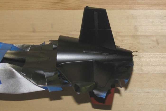
Taping to paint.
Covering ballast flood ports.
Covering the tail group and the control rods.
Inside of lower hull painting, completed.
Tape and covers removed.
This morning is cool..er and there is no wind.
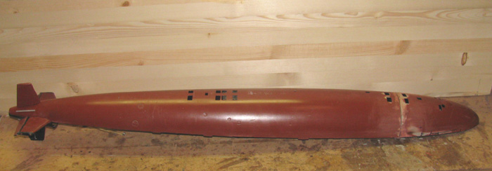
Might as well paint the bottom of the boat.
Not quite ready.
More sanding to get that shine off.
Sanding completed.
Taping completed
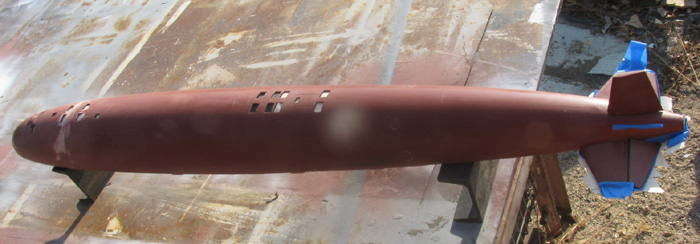
First coat applied.
Back in the shop after 3 coats.
Still need to remove the tape.
Will let it dry a little more.
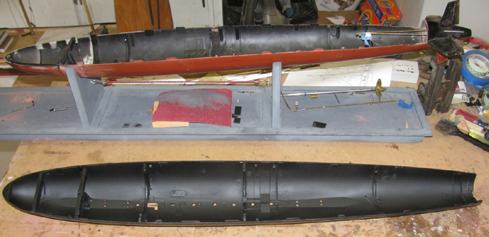
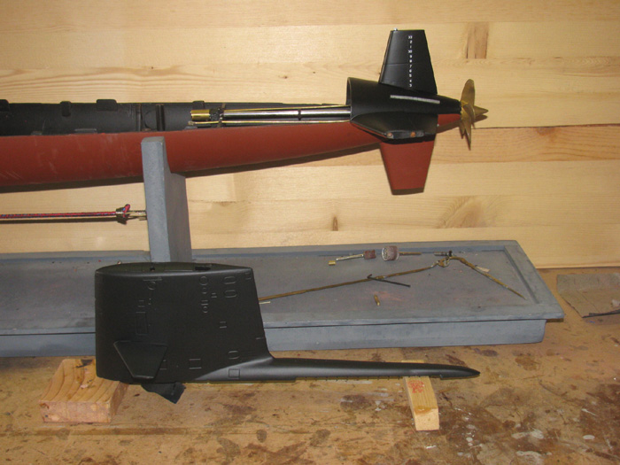
The upper hull sitting on the lower hull.
The connection bolt is not installed so the hull halves are not squeezed
together.
The inside of the sail has been reworked.
I also, removed the 2 magnets from the sail plane control horn.
I am moving the magnets to the back of the cylinder and putting the
Z bend control rod at the sail.
This will keep the control rod in the upper hull, instead of laying
on top of the cylinder when the upper hull is removed.
I was using the cylinder retaining Velcro strap to also hold the control
rod.
It worked well but at times was in the way when trying to work on the
lower hull of cylinder.
I applied primer and a light coat of paint over the upper hull in front
of the tail cone where I had been working with glaze.
Currently the upper hull has been sanded up to the draft marks.
Need to tape off the draft marks before sanding the rest of the hull.
Taped of the draft marks and sanded the entire upper hull.
Ready for paint.
So far this morning.
Upper hull painted and tape covering draft marks removed.
Tail group painted.
Needs another coat or two.
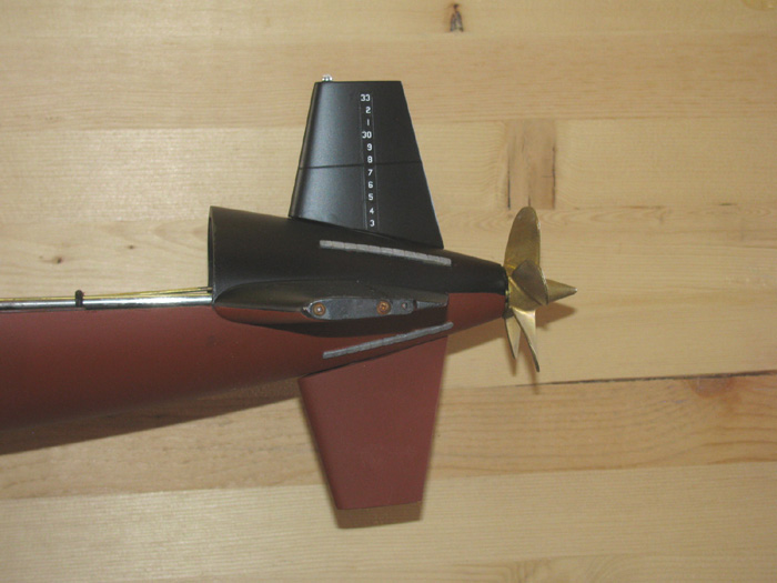
Tail group painted and tape removed from draft marks.
First coat on sail.
Closer look at tail group.
Even painted the navigation light on top of the rudder.
Silver and white.
May need more silver.
The painting of the sail is complete.
Tape removed from windows.
Sitting in place on the hull.
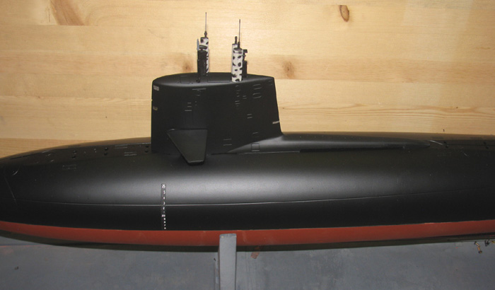
Sail installed on upper hull.
The hull modification is complete.
View from waterline.
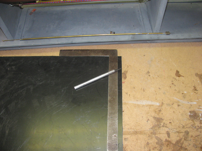
Moving on the control rod seal connectors.
I need 3 connectors, so I will build them from sheet plastic.
Using a steel square and my Exacto knife, I will make 3 1/2" x8" strips
to start.
I do not use the sharp edge of the knife.
I use the back side and drag it across the plastic against the square.
Using the sharp edge the knife blade can wonder of track.
The back edge will stay against the square by angling the knife slightly.
2 strips made.
1 more to go.
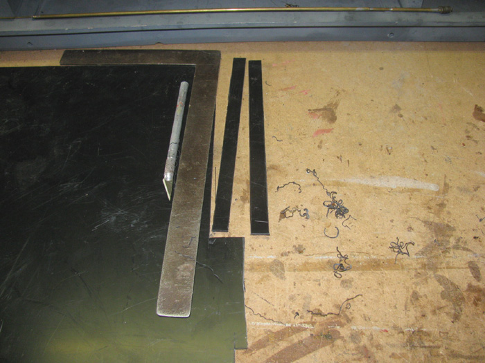
Strips cut and then I made 1" long pieces.
Takes 8 pieces to make 1 connector. 1/2"x1/2".
Cleaned up the edges of all the pieces and they are ready for cement.
Cement applied and the pieces are squared to each other 1 piece at a
time.
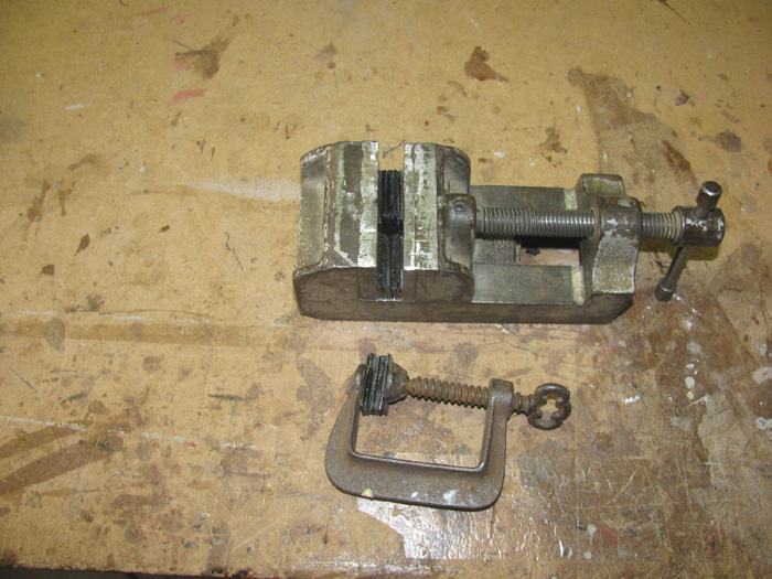
Once 8 pieces are put together, they go in the vise.
Well, 1 went in to the small clamp.
While I leave these parts to cure, I will make the parts needed to put
the magnets on the control rod.
Remember, I am turning the long control rod that goes from the sail
control horn to the rear control rod around.
The magnets were at the front and the long control rod stayed with
the cylinder.
This required a velcro strap and the rod kept getting in the way while
working on the inside of the hull.
I am turning the long control rod around so it stays in the upper hull
when the hull is open.
I need to make something that I can install and remove with just a
single set screw.
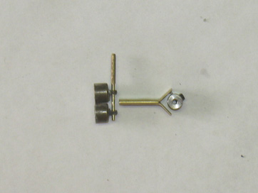
Here are the 2 magnets and the new shaft for them. (1/16" turned down
using a file and the dremel on slow)
A piece of 1/8" brass tubing split for about 1/4" and flattened in
the vise.
Hear all the parts I will assemble.
The brass tubing will be soldered to the 1/16" wheel collar. (the brass
tubing sides will be formed around the wheel collar)
A hole will be drilled in the end of the tubing one I know the height
needed.
Back to the control rod seal connectors.
I put a bolt through the plastic piece with 2 nuts to lock them in place.
This is so I can chuck it up in the drill press and turn it.
Clamping my home made cutter in place.
Moving it in until it just touches the high side of the part.
Run the plastic part up and down, slowly, against the cutter.
After getting a smooth cut, then I tape the far end of the angle iron
cutter to move it closer to the part.
Keep doing this until I get the size I want.
5 or 6 times is what was required on this part.
Then I cut a shoulder at the bottom of the part that will be inserted
in to the end cap, where the o-ring currently is.
First part roughed in.
More cutting to fit after I get the rubber boots.
All 3 parts turned for now.
Ready to turn the plastic pieces.
Well, this didn't go as planned.
During the turning, the plastic heated up enough to make the parts
deformed.
Tried turning another one with the same results.
This project failed.
======================
Time to think of something else.
Got several scrap pieces of brass tubing.
Found one that the rubber boots slipped over with a little effort.
Tight fit!
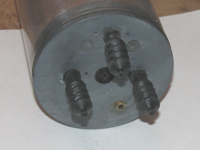
Removed rear end cap.
Removed the seal pressure plate to get access to the o-rings.
Removed the o-rings.
Removed the brass tubing push rod bearings.
Looked it all over.
I think this will work.
Cleaned the silicone grease off with detergent and nylon brush.
I cut 3 short lengths of tubing that the rubber boots fit tightly over.
Found a drill bit the same size as the brass tubing pieces.
To the drill press to drill the center off the o-ring recess in the
end cap.
The tubing requires a bit of tapping to get them in all the way to
the bottom of the recessed ledge.
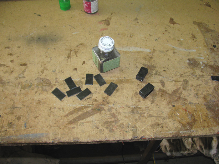
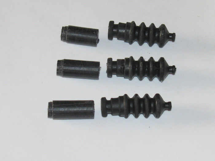
Here is the three steps.
Lower left is a piece of the brass tubing that the rubber boot slips
on with a short piece of brass tubing that will be the push rod bearing.
The center boot has the brass tubing inserted to check fit.
The top boot is installed on the brass tubing installed in the end
cap.
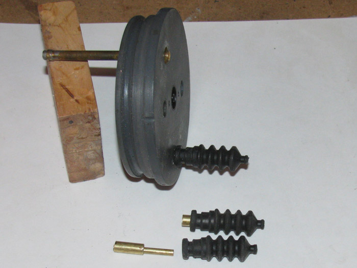
2 boots on and the 3rd brass tubing installed.
When the brass tubing is installed the the newly drilled hole there
is a 1/16" gap t the outside of the old o-ring recess.
I filled this with CA glue and used a piece of piano wire to poke at
it to make sure there were no air bubbles.
Files down the glue that was raised above the end cap until flush.
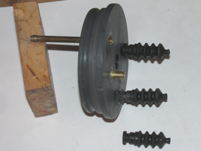
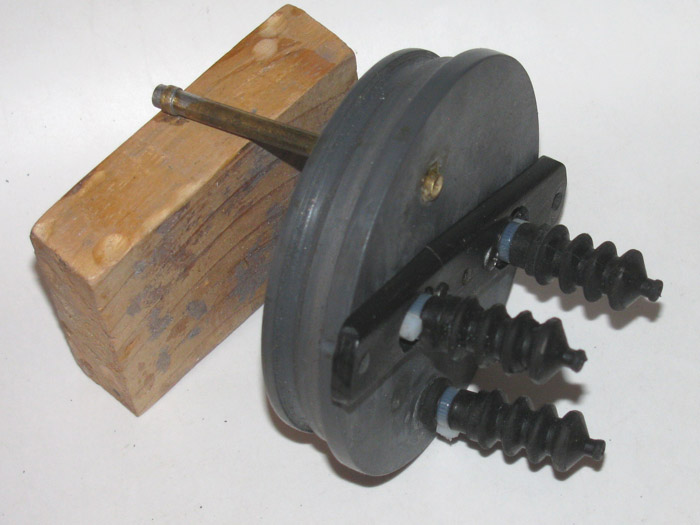
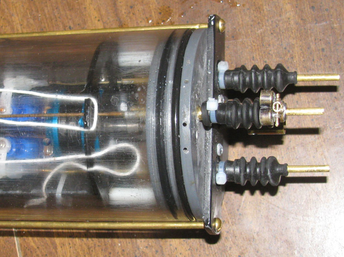
A look of all 3 boots on.
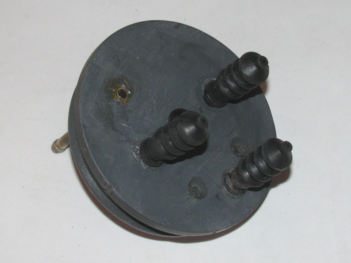
End cap sitting in the cylinder.
The seal pressure plate has been cut down making a straight bar across
the end cap.
It only needs to be there for the long brass rods that go from end
to end of the cylinder to keep the end caps for popping off when under
internal presser.
The pressure plate holes for the 2 new connector tubes have been enlarged
to accept the rubber boots and the tie wrap end.
The propeller shaft seal was removed, cleaned, regreased with silicone
grease and reinstalled.
The rubber boots can be installed with tie wraps before the pressure
plate is put on.
2 small screws, 1 on either side of the shaft seal are tightened up.
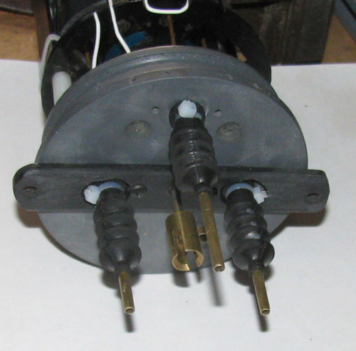
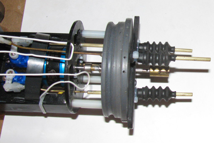
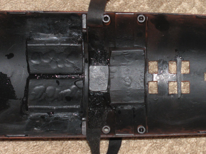
This photo is of the completed modification, ready to be put back on
the electronics tray and in to the cylinder.
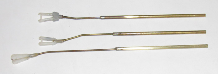
Polishing the control rods. (bottom to top..sail planes, rear planes
& rudders)
Bottom one is complete.
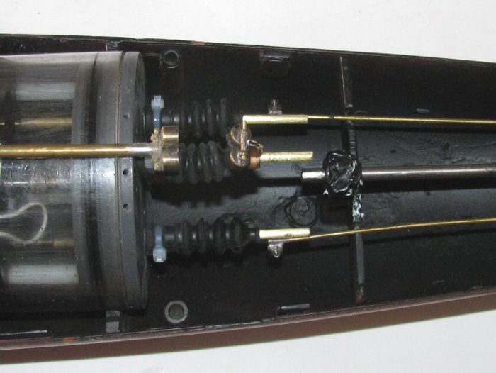
Control rods and end cap reinstalled on the electronics tray.
Side view.
The plastic pressure plate worked well when originally made to cover
half the end cap.
I cut it down because of the changes made removing the o-ring seals.
Well, it became so weak that it broke.
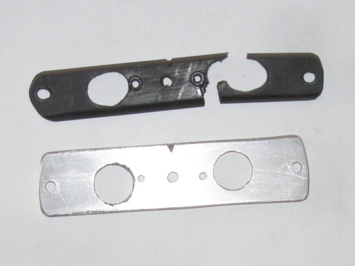
Thought about gluing it back together but decided to make the pressure
plate out of aluminum.
The notch a the center is the top location mark. (it will not wash
off)
Making the sail planes magnetic connector.
The magnets were at the sail end of the control rod are now on the
rear end of the control rod.
I have to make new parts.
I made them a few days ago and now it is time to assemble them.
My magnetic connectors are made from two jeweler magnet sets.
They are about 1/4" in diameter.
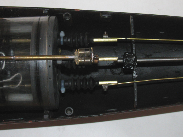
Here the connectors have not yet engaged.
Here the connectors are connected.
They are self aligning
I still need to make some sort of hanger in the upper hull so the control
rod will stay up in the hull when the upper hull is removed from the lower
hull.
Trimming completed.
Double o-ring
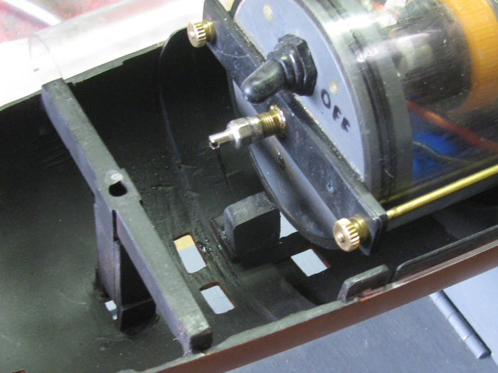
Time to work on the cylinder stop blocks.
In this photo, the cylinder with the back end in place against the stop
block is sitting on top of the stop block.
Look closely and you can see the cylinder is on top by about 1/16".
I took a file to the stop block to taper the block to allow the cylinder
to drop down.
Well, that did not work because the block moved as I tried to file it.
Did a little checking and with my Exacto knife, I realized the block
was installed using silicone glue.
Removed the cylinder.
I pinched the block between my fingers and with a little twist, the
block broke free and lifted out.
Cleaned off all the silicone from the block and the block seat
Put the cylinder in place to make sure the back end still lined up the
control rods and drive shaft.
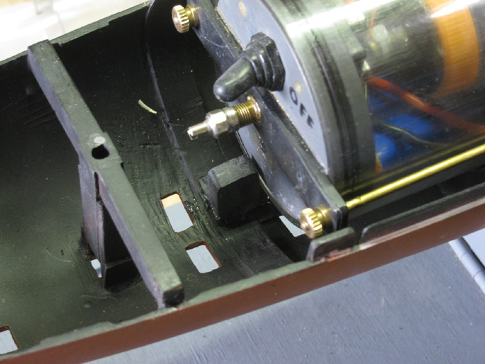
Put silicone on the bottom of the front block and set in place.
In this photo, you can see the cylinder is down with the block well
above the cylinder edge.
This entire modification took 15 minutes.
I think it would have been the same if the block had been filed.
While I wait for the silicone to cure, I started taping off the hull
to paint the alignment tab.
The tab is black plastic sheet but there are a few spots that have
red glaze that I will touchup with flat black.
Then on to the red oxide bottom paint.
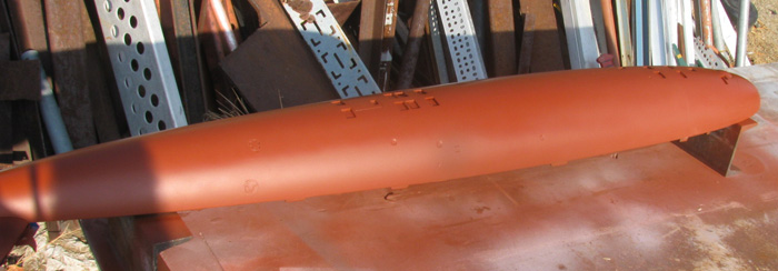
Sanded and painted bottom.
Here is the tab with over spray on it.
Not a good look.
Here I have painted the tab flat black.
Ooops. I touched the side of the hull.
Will have to touch up that spot. (center of hull)
I will let the hull dry and do the touch up tomorrow or later this
afternoon.
|