| August 2nd ================================================
My Gato project is on hold waiting for parts that may not come do to
No Trade with China.
I have to do something, so, I think I will modify the George Washington,
again. Modification #3
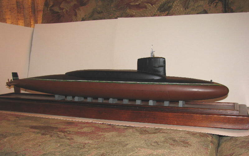
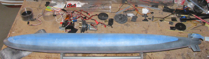
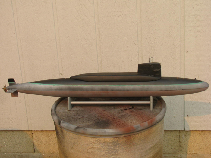
The boat has been moved to the work bench to start the modification.
This will be a down to the bare hull and a new cylinder.
Removed the sail. (2 screws)
Remove the upper hull. (1 screw under bow)
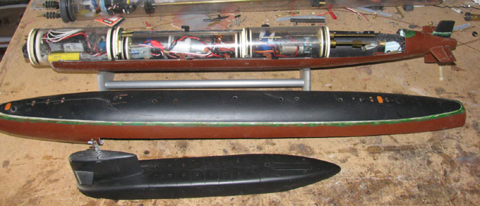
Remove cylinder.
Removed all the foam and lead ballast weights.
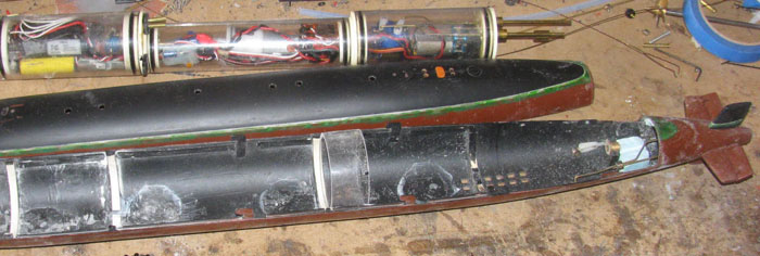
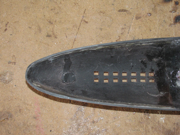
The frames for the current cylinders are 3 different heights.
I plan to install a single long cylinder so I need to grind the 4 that
the new cylinder will sit on.
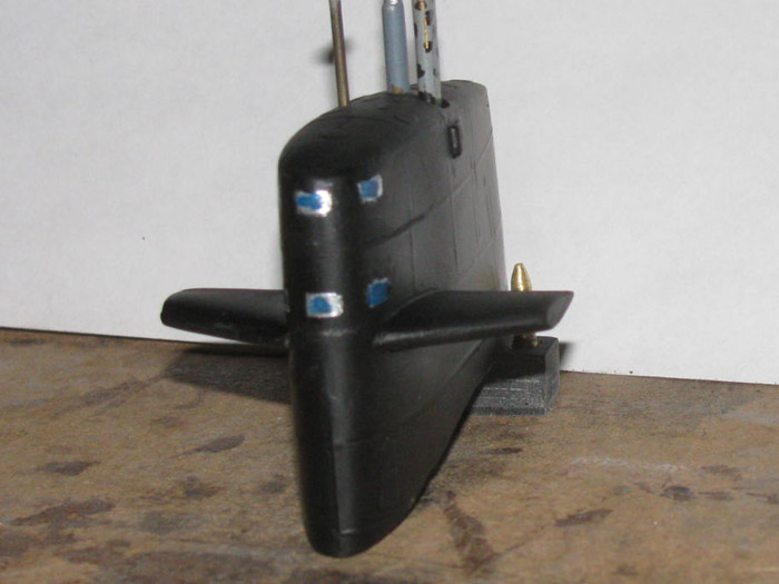
In the photo there is a test piece of cylinder sitting on 2 frames.
Those 2 and the 2 going towards the bow have been ground down to fit
the cylinder. (frames are now white)
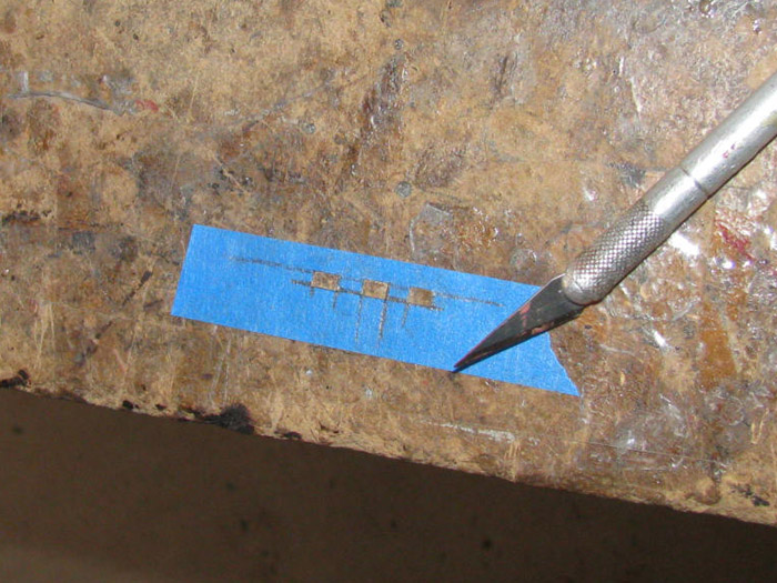
Next was to cut off the lower hull. (no more Z cut)
I did this to my Skipjack some time back
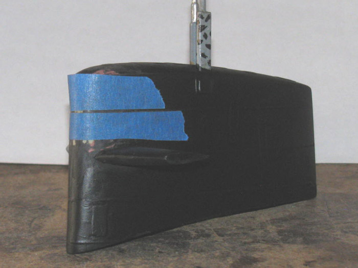
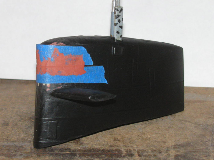
Taped the upper hull to get a straight line.
I made a starting cut on both sides following the tape.
Cutting with the razor saw was not as easy as I thought it would be.
Reason, I had fiber glass taped the joint on the inside.
Thought I would make a guide line by making a line with the Exacto knife.
Hey, the knife is following the original hull seam line.
I scribed down to the fiber glass tape.
Then I finished with the razor saw.
This took about 10 minutes.
The bow is now separated from the upper hull.
I placed the upper hull on the lower hull without the bow lower.
I lined everything up and taped it in place. (rear upper hull joint
is tight)
Turned the hull upside down and placed it on the stand.
I spent some time making sure the lower bow fit and lined up with the
upper bow.
The razor cut has a small dip near the front.
Turns out this dip lined up the upper and lower bow pieces and they
do not move around.
Maybe 1/32"-.
I was going to use plastic cement to bond the lower bow to the lower
hull.
As I cleaned the parts for glue, I realized the glass tape will not
take the cement bond.
Okay, I used medium CA glue to tack the parts together.
5 spots on the outside hull joint.
Wiped excess off.
Waited 10 minutes and then filled the gap with medium CA.
Stayed away from the ends so as not to glue the lower to the upper.
One it has cured, I plan to fiber glass tape the joint on the
inside.
The tape pieces are holding the bow together, tight and straight.
As long as I don't bump it, it should be good.
August 3rd ================================================
Today I had several places to go in town.
But before i left, I went out in to the shop while it was reasonably
cool and checked the GW hull halves.
I cleaned up the new lower hull and bow joint.
Did a quick sanding of the area I will put epoxy and glass cloth.
There is a step because of the old indexing lip.
So, I put a narrow piece of cloth down next to the lip edge.
Then I put a wider piece of cloth covering the lip and the lower area.
I will get a photo next time out to the shop.
This will keep the bow and hull together and not stress the plastic
joint.
Next I will fill the outside joint gap to get a smooth hull. (it isn't
much as the gap is tight from before)
Gap filled with medium CA and the top coat hit with baking soda to
cure it so it does not run off the sides.
August 4th ================================================
I started the morning by sanding the new bow joint down ready for glazing.
I am going to cut the upper hull at the back.
I am moving the cut closer to the stern planes as I did with the Skipjack.
Better access to the control yokes. (big fingers)
I need to remove them to replace the steel grub screws with stainless
screws.
May end up making new yokes if I can not get the screws out.
They have been in there for years.
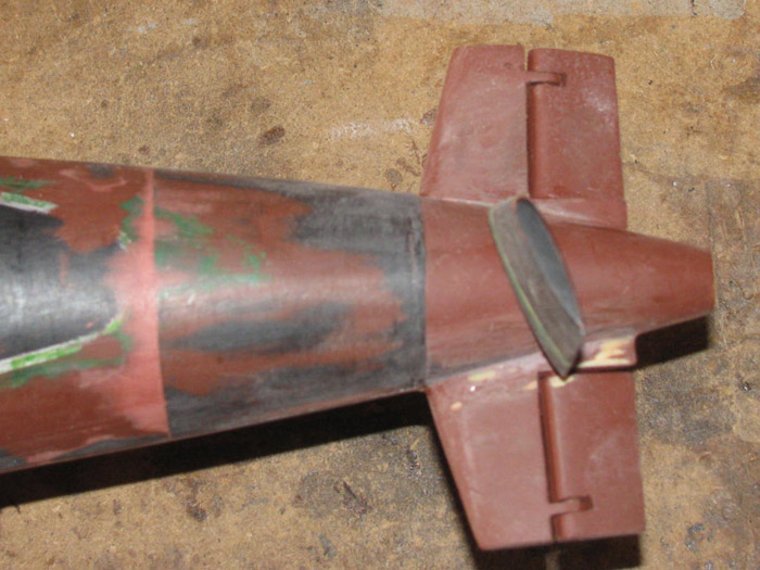
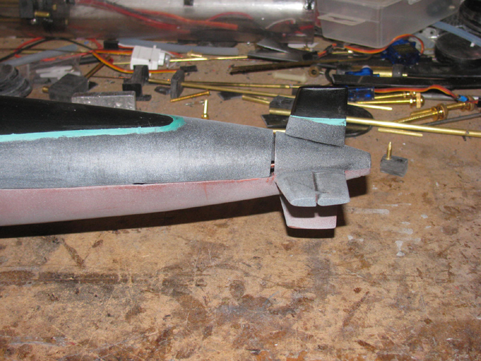
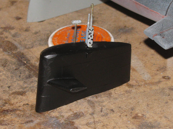
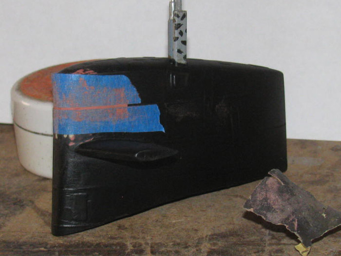
Now to cut the stern tail cone back closer to the rear planes.
When I put the boat together originally, I assembled the rudder and
stern planes before I glue the tail cone closed.
Since I built this boat, I have not been able to reach the wheel collars
on the rudders and stern planes.
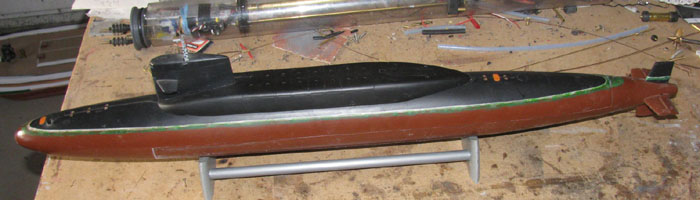
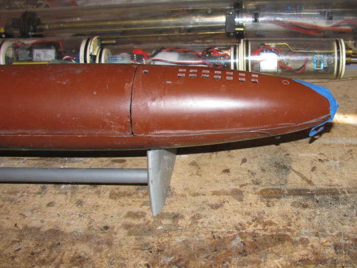
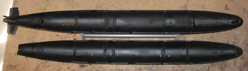
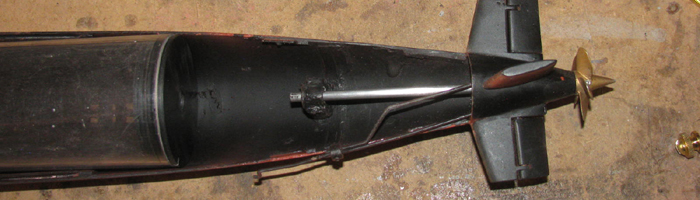
The photo shows the original cut on the right and the new cut on the
left next to the rudder.
Moving the tail cone joint back gives me 2" closer access to the rudder
and stern planes yokes.
Cleaned up the old inside lip so the cement will bond.
Cleaned the under side of the rear tail cone of foam and silicone down
to the plastic for better cement bonding.
Put the hull up on 3/4" wooden blocks to get the hull straight.
The tail cone section is also in line with the hull.
Applied medium CA to both parts and pressed together.
After 3 minutes, I turned the hull over and applied more CA to the
lip joint and turned back over and put on the alignment blocks.
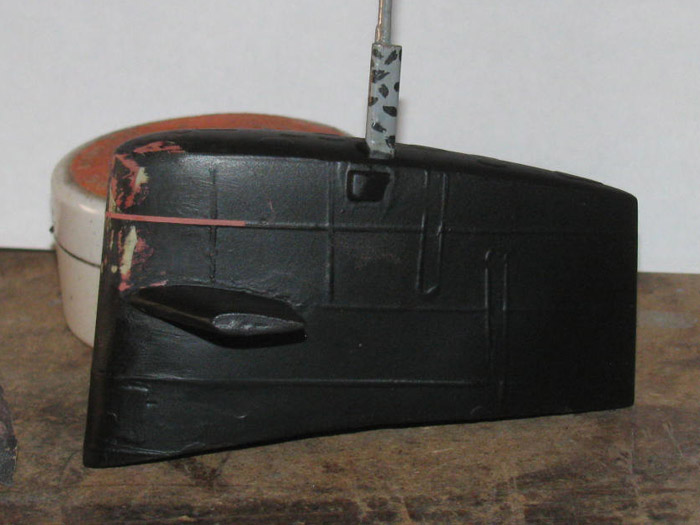
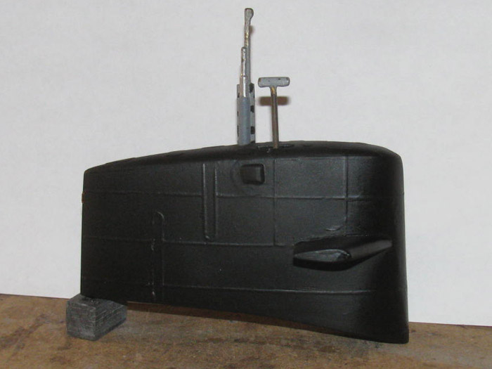
Access to the rudder and stern planes yokes will now be possible.
The tail cone section was bonded to the upper hull.
An index lip was made and installed.
Currently held by the 2 clamps.
Both the upper and lower hull joints have been sanded down flush.
Glaze has been applied in to the joint gaps.
There wasn't much of a gap on either joint.
I sanded the entire lower hull so it will be ready for paint after I
clean up the glaze.
I have not decided how I will repaint the upper hull.
Early as it is now or centerline split like it was when I was assigned
to the GW.
(got to watch the yard crew paint the boat)
After about 3 hours drying time, I sanded down the first glaze coat.
I see a few hairline cracks, so a second coat of glaze on the offending
spots.
Sanding will be tomorrow.
August 5th ================================================
Sanding is complete.
Then while looking over the lower hull, I found a blemish at the stern
just in front of the stern planes.
I could have probably filled it with primer.
But I went and filled it with glaze after using a metal pick to dig
out the little blemish.
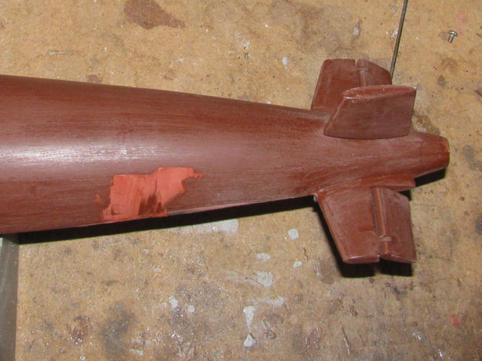
Will sand it later today.
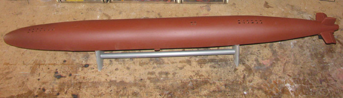
Sanding complete.
This will make the lower hull ready to paint.
I checked the fit to the upper hull.
There is work to be done but it is on the upper hull.
So I prepped and painted lower hull.
August 6th ================================================
Got a late start today.
Had in town stuff to do.
I put the upper and lower hull halves together to check for gaps.
There is a zero to 1/32"+ gap on both sides about 2" long.
This was after making sure the hull and tail cone lined up.
I cleaned the upper hull edge and made a doubter for one side.
The other side was already doubled.
Made 2 plastic strips 2.125" long and 1/4" wide to lay on the edge of
the hull.
After bonding these to the hull and clamping it all together to cure,
I decided to check the propeller shaft alignment in the lower hull.
As originally built the shaft was close to 1/16" off center.
I removed the forward bushing.
It was set in silicone so all I had to do was start an Exacto blade
between the bushing and support.
The bushing pulled out easily.
Cleaned of the silicone from the bushing and the support.
Got my half round file out and made the support a little wider on the
side the bearing needed to move.
Spun the propeller shaft to clean it up and remove the set screw bump.
The tail cone bushing is also set in silicone so moving the shaft in
a circular motion, the bushing move enough to center this bushing with
the other.
Put the shaft in the tail cone and through the forward bushing.
Spinning the propeller told me there was no binding.
Removed the forward bushing and applied silicone to the outside of
the bushing.
Placed it on the support and slid the propeller shaft through both
bushings.
Measured for center of hull and level with center line.
Braced the shaft in place and will let the silicone cure.
With bushings place in silicone, they are easy to adjust after curing.
Figure out which one is not straight and heat it with a soldering iron.
When the silicone get hot, the bushing will move.
When the silicone cools, the bushing will stay in place.
I move mast in the sail the same way.
I put the end of the soldering iron in the brass tube glued in the
sail until the glue or plastic gets soft, then move the mast to straighten
it.
Be careful not to heat it all too hot.
Really bad things can happen.
But nothing that can not be repaired. (yes, experience)
After I get the gap fixed at the rear of the hull, I am going to work
on the bow gap.
There is not a gap but the hull halves centerline is not straight.
The cut line has a drop going back about 8".
The hull mates fine but I do not like the drop.
The fix is the same as the rear except I would file the upper bow up
level and add the strips of plastic to it.
The lower hull will l need the same.
This is all to make it look better.
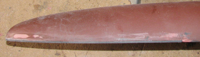
Here is a view of the plastic strip added to the edge of the tail cone.
It needs to go from zero on the left side to about 1/32"+ on the right
side to fit tight on the lower hull.
There is the top view showing the plastic strip sticking out bast the
hull side.
The strips have been sanded to the hull sides.
The inside has been trimmed to the hull as well.
There is still a little more sand to do to get it flush but I will
do that when the two hull halves are together to get them shaped to the
full hull.
The glaze on the right is on the index lip.
When I put the hull together, there was a small gap on each side.
The top mates up tight with no effort.
The propeller shaft bushing silicone has set up.
Not cured but safe to handle the hull.
August 7th ================================================
Looking at the glaze before getting after it with a file.
I have sanded and filed down the glaze on the upper hull stern lip.
The fit is good but there is still a small gap on one side.
I reapplied glaze and will do more work on it after it cures.
Sanded the upper hull where there were two small blemishes.
Looked good so I continued and sanded the compete upper hull.
Left about 2" at the stern where I am working the glaze.
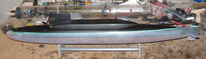
I had an idea to use the stern section of the original cylinder.
The motor and 2 servos live there.
As I sat the cylinder in the hull and the new cylinder next to it,
I measured the new cylinder (cylinder sitting under the work bench for
some time) and it will fit to the aft cylinder index mark without having
to use the original smaller cylinder.
All I have to do is grind the rear frame down to accept the new cylinder.
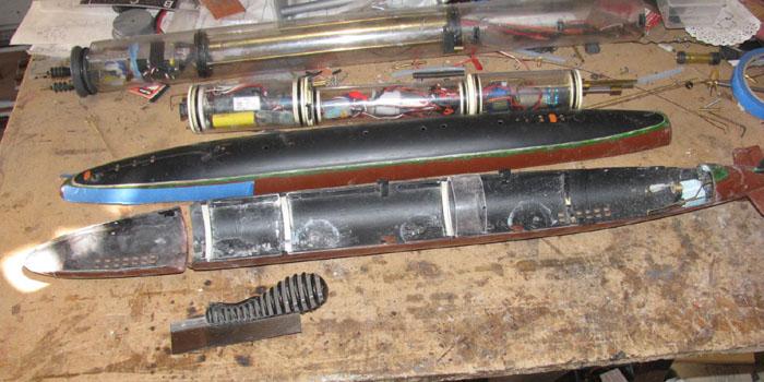
So I ground down the frame in the upper and lower hull.
As I was grinding, I test fit the new cylinder to make sure it was
centered in the frames.
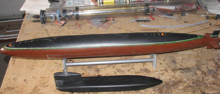
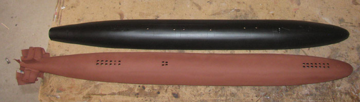
Here the frame has been ground down and the old cylinder sits next to
the hull.
Another photo with the new cylinder sitting in the hull.
The new cylinder is still 1/2" longer than the old because that is
all that will fit.
This leaves room to cut it shorter once I get all the electronics in
place.
The rear of the cylinder is the index end.
It will be the same for nt new cylinder.
The old cylinder had the ballast bag on the outside.
The new cylinder, hopefully, will have the ballast tank inside.
I have been working on the bow gap.
On one side the cut is not straight.
More like a wave.
My fix was to cut the hull down to make it straight. (about 1/16"-
material was removed)
In this photo, the problem is from the white frame to the bow center
plus 5/8".
August 8th ================================================
After removing material, I cemented 1/16" thick sheet plastic on the
edge of the hull.
I also added 1/16" plastic to the bow center to 5/8" on the other side.
Here is the look from the outside of the hull.
Ready to start trimming.
I will sand this new plastic flat to make the hull straight front to
back.
Once done, I can work on the other hull half using the completed half
as my guide to get a tight fit.
Glue, sand, file to fit.
Been here before.
I used the Dremel to remove the bulk of the extra plastic.
Then I used a rough file.
On the outside, I did the same but I finished with a wooden block and
150 wet/dry sand paper to get the plastic down to the hull.
Here the plastic strip can be seen.
I have started on the other side of the bow.
It is a long section from the frame forward stopping short of the bow
at about 1.5".
The bow front end happens to be right on the mark of straight.
I have been using this point to level every thing else.
Here is the finished tail cone joint.
The joint is at the front edge of the rear planes.
I have to put the tab on the left hull to hold it down to the tail
cone.
I removed the original to get a better angle with the Dremel and file
on the inside of the hull for trimming.
Last update for today.
All the gaps have been fixed.
The tail cone alignment tab has been installed and fitted.
With the 2 hull halves joined, I looked over the centerline cut.
There were 4 little ding gaps that I filled with glazing.
I will sand those down tomorrow.
I will get a primer coat on both halves tomorrow.
Actually it is a paint with primer in it so if it looks good, I can
leave as the finish.
The top hull will get the paint with primer as well.
I will look this over for flaws and fix them if need be.
Then I will paint the upper hull flat black.
Got to remember to do the inside first so any over spray from the outside
won't matter, much.
My plan is to get out to the shop early Monday morning before it gets
hot and turn 2 end caps.
I will also cut a piece out of my aluminum material to make a long
electronics tray.
It will go from end to end, (I hope)
I want all the electronics to slide out of the cylinder on the tray
from the back of the cylinder.
Nothing out the front.
What I am thinking is this, if I can get everything on the aluminum
tray to slide out the back as a single piece, I may bond the front end
cap permanently to the cylinder.
August 9th ================================================
Sanded both hull halves for paint.
Did 1 little glaze spot and it has been sanded.
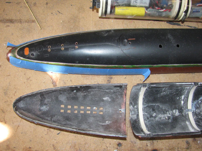
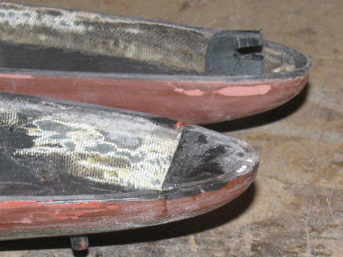
Was getting the paint out when I remembered, I needed a lug at the bow
to how the hull tight together.
In this photo you can see the 2 lugs on the side of the upper hull.
(bottom in the photo)
Time is close to making end caps.
I have several rejects from other projects that used bigger cylinders.
I should be able to find a few pieces I can turn down to the smaller
cylinder diameter.
Sanded both hull halves for paint.
Did 1 little glaze spot and it has been sanded.
Was getting the paint out when I remembered, I needed a lug at the bow
to how the hull tight together.
In this photo you can see the 2 lugs on the side of the upper hull.
(bottom in the photo)
When the hull halves are put together, I have to slide the hull 3/8"
to get the top to go back to the tail cone.
This causes the lugs to engage and pull the hull halves down together.
I am making a heavy duty lug that is going in the bow on the centerline.
(1 lug)
There will be 1 stainless screw back at the tail cone (just in front
of the rudder) to keep it together.
I am currently doing the shaping and fitting of the lug.
I need it to be tight and not let me push the hulls all the way together.
After the glue cures, I can file fit the lug so it is tight and the
hull goes all the way to the tail cone.
I remember this being a very slow process when I did the original lugs.
I remember having to make several to replace the ones that failed by
filing too much off.
At least this one does not have to follow the hull diameter curve.
Here is the bow lug which hooks on the plastic plate in the bow in the
lower hull.
The lug has been test fitted and files to lock down the 2 hull halves
correctly.
I did notice I need to put 2 small guide strips of plastic, 1 on each
side of the lug plate (the flat plate) to keep the bow from moving side
to side.
It is only 1/16" plus both sides but it can be seen.
The 2 guide blocks have been installed.
Time to paint. (flat black)
I have completed the inside of both hull halves.
I was going to paint the outside but I am not sure I have enough paint.
I am going to town tomorrow, so I will stop and get more.
While typing the above, I got to thinking about the paint.
Hey, I only need to paint the top hull, flat black.
I bet I have enough to do that.
I was right.
Here are the hull halves painted on the outside.
I haven't even pulled the tape off the planes.
While painting the lower hull I noticed that the paint was primer and
not paint with primer.
Seems I had some red oxide left.
Okay, I still have to go to the hardware store for the other paint with
primer.
I like the look of it better.
August 10th ================================================
Finally back from town.
Got the stainless bolt to hold the hull halves together.
Bad news, the correct paint on the shelf.
Asked. Might be in tomorrow's delivery.
This morning, I test fit the upper and lower hulls together.
My bow lug is too tight after painting.
So a little filing and that is corrected.
I want to put the waterline back on the hull.
Going to have to build something to hold the pencil at the right height
to draw the line for taping.
Simple stack of wood blocks and a clamp should do it.
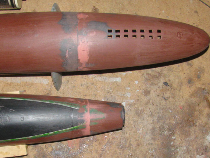
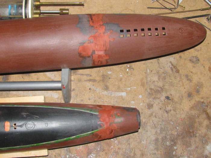
Why the waterline on a black hull.
I am going to try a little. . .very little. . .weather on the bottom
of the boat.
But before I do that, I will do a few test runs on a hard board paper.
I think I want the bleached look.
[img]https://i.pinimg.com/originals/6a/bf/34/6abf348388e2e817f37e477f77461f94.jpg[/img]
This could turn in to a mess very quickly.
====================================
Bad news from store.
The color and brand paint is no longer made.
This happened a couple of years ago.
I used Red Oxide as bottom paint.
It was discontinued in California.
I changed to a new Ruddy Brown which I liked very much.
Better color and was paint and primer all in one.
This is what I didn't like about red oxide.
It has to be clear coated or it soaks up water.
Looks like I am back to the Red Oxide primer.
----------------------
I happen to have 1 can Red Oxide I kept on hand for touch up.
This morning I see it is back on the shelf.
August 11th ================================================
Not much to report.
Was in the shop making sure the bow lugs fit and made the hull come
together tight.
By pulling the bow together, the middle of the hull separated just
a little.
Maybe 1/32"+ for 6" to 8".
This is where the other lugs are located.
So they are not tight enough and allow the hull to move apart.
I looked at the original lugs.
3 or the 4 are made of a single piece of sheet plastic.
The 4th is doubled up.
This double up lug gives me more material to work with in the way of
filing a ramp to pull the hulls together.
It allows me to add a sliver of plastic to make it tighter and then
file to fit.
Well, I can not leave things alone.
I removed the 3 single layer lugs and made new double thick lugs.
Cleaned the hull where the new lugs will go to remove all paint so
the bond is plastic to plastic.
I shaped the new lugs which are basically "L" shape pieces with a slight
ramp on the lower leg of the "L" to pull the hull halves together.
I also have to shape the lugs so they fit the hull curve.
So a little Dremel work with a 1/2" sanding drum.
Then there is the measuring from stern joint to lug catch. (this is
what the lug holds on to)
The lug needs to be measured for height. (I hold the lug in place on
the catch and scribe a line)
When I glue it in place on the other hull half, I hold it down on the
mark.
This will make me file to fit because it will be too tight to start
with.
Time passes,
The back 2 lugs have been fitted.
One at a time so I can get the lug to catch fit correct before fitting
the next one.
Right now I have 2 lugs mounted and fitted.
I have 2 lugs in the table vise holding while cement cures the next
2 lugs.
I need to make a 5th lug.
The distance from the second set of lugs which are about mid hull leaves
along distance to the bow.
2 more lugs, half way to the bow will even out the lugs.
These lugs not only hold the hull halves together but because they stick
up above the hull edge, they hold the diameter and aligned in check.
----------
4 lugs installed and fitted.
2 more to go.
Maybe. I have not looked to see if I can make the receiver for the
lugs in the upper hull.
Might require cutting some edge grooves out.
So I made a little progress.
August 12th ================================================
I have made and installed all the lugs.
There was some trimming to get the hull centerline joint tight. (enough)
Put the cylinder in the hull and closed it up.
At least I tried to close it up.
The upper hull was up about 1/32+ in spots.
Well the only way to fix this is to grind on the frames some more.
Using along straight edge ruler, I went across the frames looking for
the high frames.
I can not believe how straight I got then first time around.
I started on the bottom frames.
I took them down to about 1/8 from the hull bottom.
Got them level with my straight edge.
Still the upper hull will not fit down tight enough.
Next, I trimmed the upper hull frames.
I did the front most frame and the back most frame.
I Ground on the center frames a little at a time
I taped 3 pieces on the straight edge ruler to get it up over the frames
that where too high.
Put piece on the ruler so they would sit on the 2 frames at each end.
The third block was over the frame being ground.
Slowly ground on the frame until it was the same height as the front
and back frame.
Moved the block to eh next frame and did it.
Got to the last frame and slowly worked it down.
Now all 5 frames are level.
Now I can test fit the cylinder in the hull.
I just know I will need to go through this again to get the frames down
so the hull closes up correctly.
Yep, it took 2 more times to get it right.
Now you may be wondering why I didn't grind more off the bottom hull
frames.
The answer is I left 1/8 under the cylinder for lead sheet ballast
strips.
I may have to put some lead in the cylinder when I get to trimming
the boat.
I will leave a place for block lead in front of the ballast tank and
after the batteries.
I see more painting or repainting in my future. (inside the hull to
cover the exposed white frames)
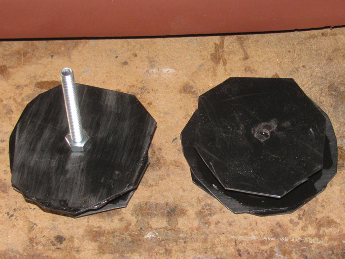
I found 2 end caps from another project that got rejected do to the
o-ring groove being too deep.
The nice part is they are 3 diameter and I need 2.5 diameter. Good
start.
August 13th ================================================
Had to go in to town this morning.
The town 24 miles away.
Got back and out to the shop I went.
It got hot early so there was no working in the tool shed turning end
caps.
The tool shed has no windows and works like an oven.
So the shop it was.
I worked some more on the hull joint lugs.
Got the hull joint as tight as I think I can but there are places with
small gaps.
Looks like I am going to have to do the build up of glaze on one of
the hull pieces to get those gaps closed.
The clear packing tape with a little silicone grease on one hull and
then squeeze the glaze in to the gap and let dry for a day or two before
opening up and seeing what I have.
In the past, this worked well and only required a little clean up.
----------------
Still thinking about what type of ballast system to build.
Last night I was think I should look in to small solenoid valves for
the air vent valve.
So I did just that.
There was one image showing the inside of the valve and it got me to
thinking about the vent valve on the Gato.
The Gato vent valve is on top of the cylinder and worked by a servo
in the rear compartment.
Bit the GW does not have the room for a valve mounted on top of the
cylinder.
But thinking about it, if I turned that valve over 180 degrees, I could
mount it in the cylinder on the ballast tank end cap.
Then run the rubber hose from the tank through the valve to the rear
end cap keeping the hose at the inside top of the cylinder.
In a slight dive, the vent hose would be angled enough to take all
the air out of the ballast tank.
I made a couple of drawings and I think I can make it using sheet plastic
(of course) and two 1/8 o-rings and a 1/8 brass rod.
1 servo would activate the valve and the air pump.
So I need to build the mast head snorkel valve and the safety tank in
the cylinder.
I built on for the Gato but I didn't use it.
I need to make another but smaller.
I have 2 back up plans for a safety devise should I not get the little
safety tank to seal.
These would make the boat a negative diving boat with reserve to bring
it up to sail above the surface for the snorkel to work.
I am also looking at parts to build a small piston tank but the parts
are all from China can I can not get them here.
So I am trying to put the equipment together in the cylinder so I can
later replace the ballast system with a piston system.
I have 2 piston boats and they are a pleasure to run. (I like the piston
boats)
August 15th ================================================
In to the shop by 6am.
I finished the bow lug to a point I like it.
Now with the upper and lower hulls pulled together I can see small
random gaps along the centerline joint.
Well, I guess I need to do something about those.
I cleaned the paint off the edge of the lower hull.
The lower hull has the widest edge for glazing.
I used a light silicone grease to grease the upper hull edge and ¼
up the outside of the hull.
Put the halves together carefully so as not to transfer any grease
from upper to lower hull.
Using my finger after trying a small plastic square to push the glaze
in to the joint, I worked 1 side of the hull.
I has turned hot again and I get to work about 1 to 2 at a time with
the glaze before it starts balling up.
Got it done.
Will let it cure until to morrow.
I will try to get out to the shop early in hopes the cool air has shrunk
the glaze enough to separate the hull halves without removing the glaze
from the lower hull.
If this does not work, I will clean it all off and leave it as it was.
Now 9:20am and the temp shows 103.
I quit.
August 16th ================================================
What got done today?
I started out by testing the 2 new Rx and servos.
The first one took a little time because of several tries following
the instructions.
Got help from Will and things moved much better.
Got both Rx bond to the Tx.
Also got both Rx in to Mode II which is No Fail Safe by the Rx.
I use the Fail Safe that goes between the Rx and servo.
Why you might ask.
The inline Fail Safe has a 6 to 7 second delay.
The Rx Fail Safe has zero delay which caused a lot of trouble when
running.
Next I got on to the hull gap.
Yesterday I glazed one side.
Today I sanded it down to the hull and then separated the hull halves.
I got a clean line and the gap is mostly filled.
Time to do the other side.
Sand the lower hull at the centerline.
Grease the upper hull so the glaze does not stick.
Put the hull halves together and get out the glaze.
It is already getting hot.
Doing 1 to 2" at a time using my finger to push the glaze down in to
the gap.
Then a second pass to over fill the gap to allow sanding down to the
hull.
Again the heat is causing the glaze to ball up as I spread it.
Down to 1" at a time.
Got it done.
Set the hull in the stand to dry.
Sanding will take place on Tuesday.
Tomorrow I go to the VA again, early.
But by the time I get home it will be too hot.
Example:
This morning I started at 7:30am and it was 83F.
I stopped at 9:20am.
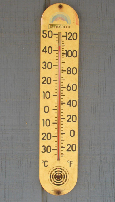
In the shop the temp reads 102F but outside on my front porch it reads
115F. (this is because I have a metal porch roof and it seems to read higher
than every where else I have thermometers.
August 18th ================================================
Everything at the VA yesterday went well.
I even got some answers that the doctors have been avoiding.
I got to see the images from the PETScan which allowed me to look for
what I had been asking about without letting the doctor know what it was.
Then we talked about it and he answer this time.
-------------
Now back to the GW.
The centerline gap closing is going well.
I sanded the second side this morning and found only 2 little 1/2"
gaps that pulled away during separation.
Cleaned up the joint edge and then put the hull back together.
Glazed the 2 spots.
When I get this done, I will paint the new glaze with thin CA glue to
seal it and to make it hard so it won't crumble during handling.
I found a plastic tube I think will work for the ballast tank.
There will be no pressure in the tank so a very thin plastic can be
used.
The tube came from weed eater strings.
It's 2" in diameter and long enough to do what I want.
A couple of end caps and 2 frames inside to help hold the shape and
I think it will work.
I cut up some sheet plastic to make end caps.
Needed 14 2.5" squares.
4 glued up in 2 layers and then there are 2 glues up as 4 layers.
There is more gluing to be done but there are 2 diameters to be turned
before I can assemble them.
I lasted until 10am before the shop was too hot to work in.
So I got a good 2.5 hours in this morning. (major progress)
August 19th ================================================
In the shop about 5:30am.
Sanded and prepped the hull for paint.
The lower hull is done.
The upper hull has first coat and needs a second coat.
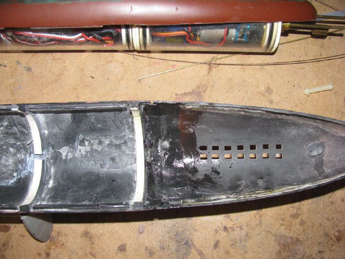
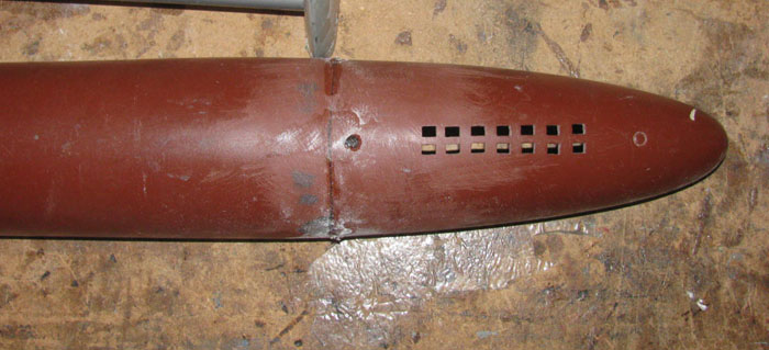
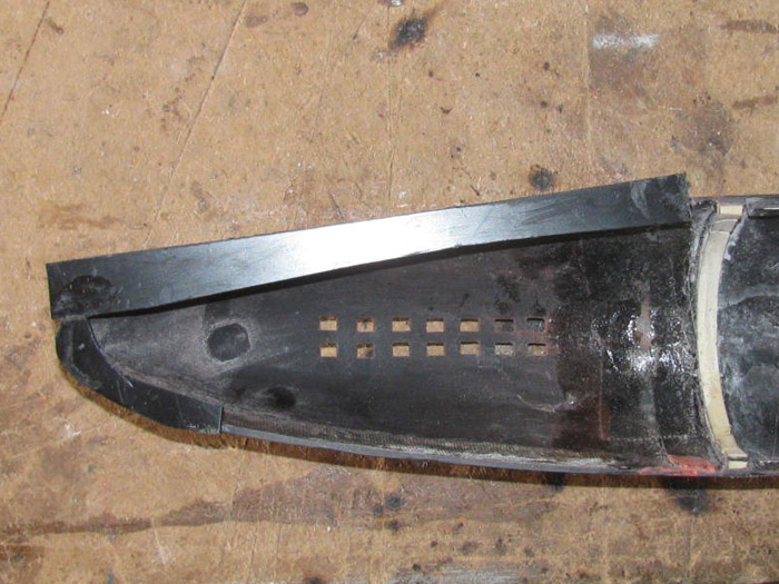
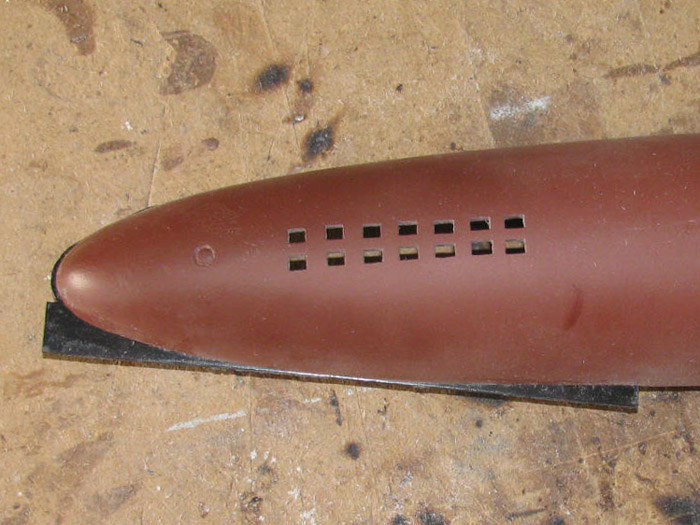
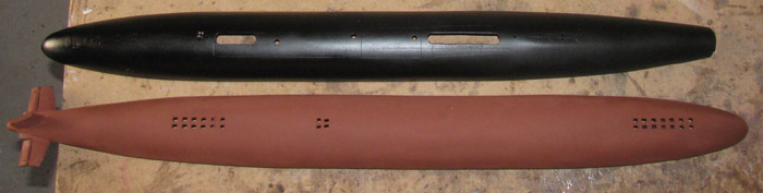
You may notice the 2 new slots in the top of the hull.
These will be under the missile deck and out of sight.
The one under the sail is where the intake for the air pump will be
located.
The slot will also let water fill and drain from the sail easier.
The rear slot is where the intake hose will drop in to the hull near
the rear end cap to be connected to a through tube.
The layers of plastic out of the clamps.
NExt is to turn them in to end caps for the ballast tank.
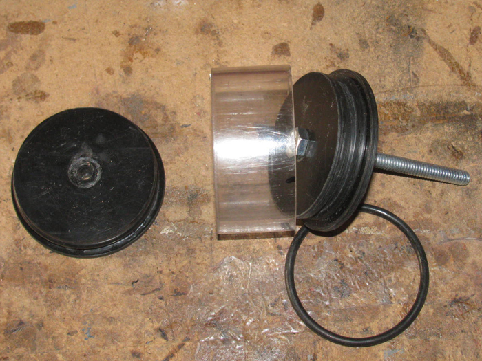
Plastic parts turned.
Left to right.
1. 2 layers to be mounted to the tube end cap.
2. Plastic tube end cap with shoulder removed.
3. 2 layer baffle frame to keep the plastic tube round. (tube is very
thin)
4. Second end cap with shoulder removed.
5. 2 layers to be mounted to then tube end cap.
Ballast tank with parts sitting where they will go.
Making sure the test cylinder ring fits over the ballast tank leaving
enough room for some wiring.
Making sure it fits in the cylinder.
Ballast cylinder inside main cylinder.
Now I need to get brass parts to make the long through bolts for the
ballast tank.
August 20th ================================================
I planned to go in to town to get paint and brass bolts, washers, nuts
and tubing.
I went out to the shop to check my stash of brass tubing and rod.
While sorting the brass tubing I found a few packages that had fallen
behind the box.
Some was just what I was needing.
So the brass tubing and brass rod is good.
I looked online to make sure which store had the paint I wanted.
Off I went.
Got there and found some brass bolts and nuts but no washers or o-rings.
Not a problem, I can get them at the local hardware if need be.
But NO paint.
Talked to worker and he said they did not have any at this store but
the other store had 24 cans.
This other store is only 7 miles away.
Sounds okay but I had already drove 24 miles to get to the first store.
Made the drive.
Got the paint and I found all the other brass bolts, washers and things.
Still no o-rings.
They had ever size but what I wanted.
I will have to look in my o-ring stash.
There should be some but I can't remember how many.
Been using then over the years.
Tomorrow, I will get up early and see if I can make a couple of end
caps for the WTC.
Then the disassembly of the original WTC starts to get all the equipment
out of it.
Everything but the ballast system will be used again. (well the switches
and servo will be used)
--------------------------------------------
I think I will clean off my kitchen table.
Bring the upper GW hull inside.
This way I can work on it during the heat of the day or evenings.
I need to draw a water line on the hull.
I am going to try my hand at a little weathering.
Actually, a little below the waterline growth and bleaching.
August 21th ================================================
Cylinder end caps have been started.
The end caps will be made in two parts.
1. The part that has the o-ring on it and goes inside the cylinder
tube.
2. This part will be the outside shoulder of the cap that stops the
cap from going all the way in to the cylinder.
I make these to go inside ballast tanks to be adjustable during trimming.
I happen to have a few of these already made up and I picked 2 that
fit tight and with the o-ring seals nicely to use.
I have cut sheet plastic and rough cut them to make turning them round
easier.
I have glued up two 2 layer pieces for the end cap ends.
They are all clamped up to cure.
I know the plastic cement bonds without pressure but I like the positive
bond when clamped to cure.
It is starting to get hot in the shop but I have to wait for the cement
to cure before the next step.
So I am going in to town for groceries, gas for the car, mail and a
stop at the hardware store for a couple of parts.
(noticed, I have no more silicone caulking or ¼ bolts that
I use to put the plastic on to turn)
I looked at the hull.
The top hull needs a little attention.
I see where the paint tried to run near the bow.
A little sanding and touch up is in order.
I will spend some time this afternoon drawing up a vent valve.
This vent valve will be inside the WTC mounted on the ballast tank
end cap with a brass tube running from the ballast tank to the cylinder
end cap.
OR I will see if I can put the vent valve on the WTC over the ballast
tank and use a couple of o-rings to push a brass tube through the WTC in
to the ballast tank.
(this seems overly complicated in my head)
Well the plan changed.
Before I left for town, the house cooler quit.
The belt broke.
The belt has the number on it so I wrote it down.
Went to town to get a new belt and some other hardware parts.
Did not get to anything else.
It's 110 degrees and without the cooler . . . . I hate to think what
might happen to me.
Got home and installed the new belt.
Adjusted it and got it going.
It will take a while to catch up and get the house cooler.
So I went out to the shop and did the next step with the end caps.
A matter of bonding more plastic pieces to together making the end
caps the right thickness.
This took about 6 to 8 minutes.
They are clamped up for the night.
THe pliers I used to turn the drill bit through the center to line every
thing up where almost too hot to hold on to.
I put a glove on to work on the second cap.
Now inside in the office sitting in front of the cooler air flow.
Makes life better and the rest of the house will cool down and I can
sit here in the cool breeze.
August 22nd ================================================
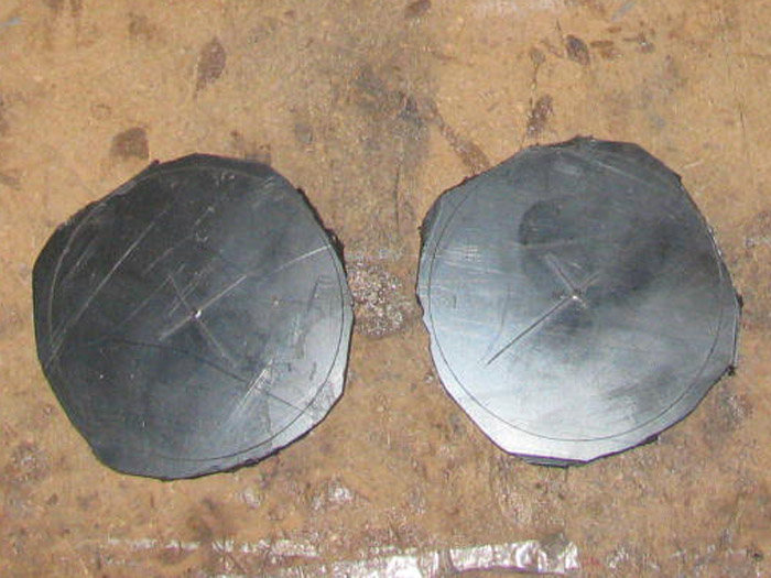
Ready to turn the cylinder end caps.
One side will be turned down to the center section diameter. This is
the inside of the cap.
The other end will be turned down 1/8" more than the cylinder diameter
to sit on the cylinder edge.
The groove is already in the center section. (the center sections where
made some time ago)
The center bolt is 1/4" diameter to chuck up in the drill press.
Both end caps have been turned.
Tested with o-ring installed in short cylinder test piece.
I put the cylinder in the lower hull and looked through the tail shaft
bushing, through the support bushing to see the end cap center hole.
If I had a longer propeller shaft, it would go through all three holes.
The original cylinder end cap was not centered and the dog bone had
to be bent a little to connect.
This is my front porch.
It is about 5 degrees cooler in the shop.
August 23nd ================================================
I made a couple of more parts for the ballast tank.
And yes, they are in the vise curing.
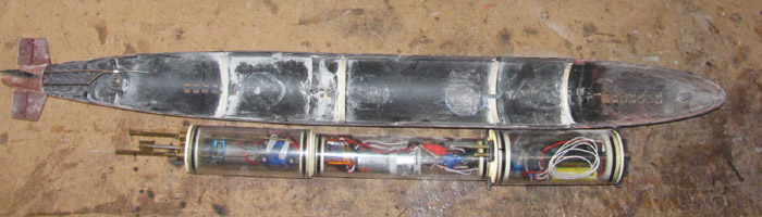
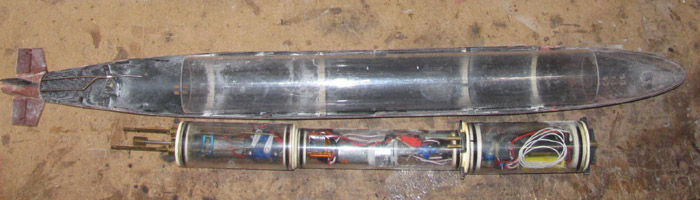
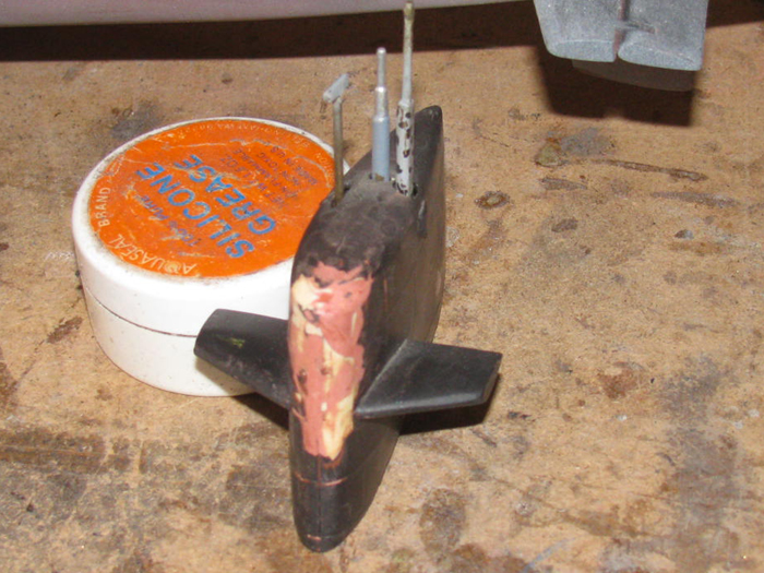
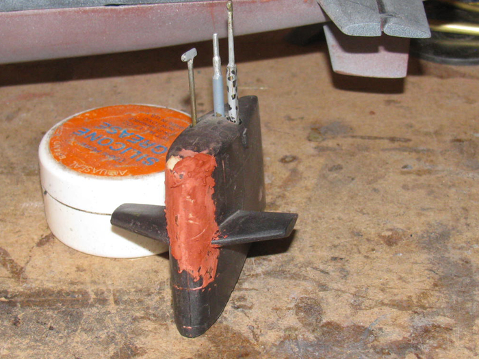
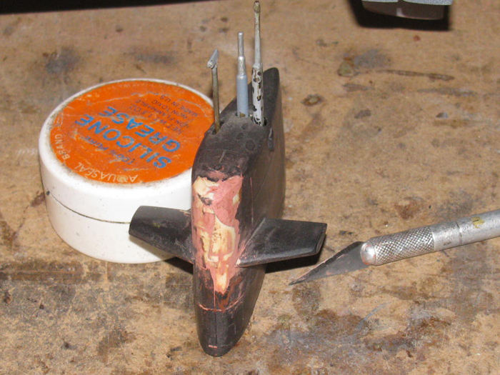
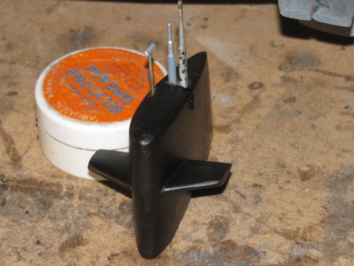
On to the original GW cylinder.
Time to disassemble it for parts.
The system was a 3 cylinder WTC.
Not in the image is the ballast bag that sits on top of the cylinder
in the hull.
These parts will not be used in the new cylinder.
The end cap on the right has a servo and vent valve mounted on it.
I didn't think to turn it around so we could see it.
These parts will be used in the new cylinder.
Main motor with gear box.
Rudder and read planes servos.
Auto Pitch Controller.
8 channel Rx.
Speed Controller for main motor.
I may use some of the end cap seals housings.
What this system did not have was a Fail Safe board.
(There just was no room for it)
There will be a Fail Safe in the new cylinder.
August 24th ================================================
I am still making small plastic parts.
The end caps for the ballast tank are made from 5 pieces of sheet plastic
each.
Each end cap has 2 large disks and 3 smaller disks.
The large disks fit tight in the WTC so the ballast tank will not move.
The inside disks fit inside the ballast tank tube.
The inside disk are mounted offset on the large disks.
The ballast tank will sit on the bottom of the WTC and leave room on
the sides and top to run the wires.
These wires are the main power from the batteries in the front compartment
to the rear compartment where the equipment is.
There is about 1/8" clearance between the WTC and ballast tank at the
top.
The small disks have been shaped and I put a small groove in the center
of the disk edge for silicone glue.
Once I get all the parts made for the ballast tank, I will glue the
end caps in to the tank tube.
Silicone in case I have to remove the end cap.
I think the tank tube is bigger than needed and is easier to shorten
than lengthen.
Good news.
While looking over the original parts, I found the Fail Safe stuck
to the under side of the main motor tray.
This means I have all the electronic equipment I need.
Just have to finish making ballast tank parts.
The vent valve is next.
It will be mounted on the rear end cap and vent in to a tube that goes
out the rear cylinder end cap when venting.
I won't know if the valve will be offset or straight inline until I
start making it.
I also need to make up 2 rods with threads on each end to go through
the ballast tank.
It has to be adjustable because I may have to shorten the tank.
These rods will hold the tank together and the threaded ends will stick
out so I can mount the electronics tray to each end.
My plan is to have all the equipment in the WTC slide out the back for
maintenance and repairs.
August 25th ================================================
Going to see what I come up with in the way of a vent valve.
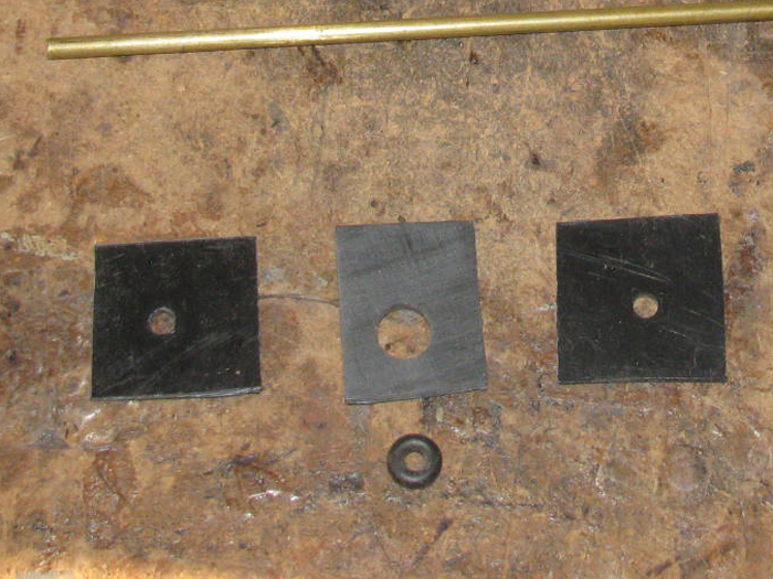
Gather some scrap plastic sheet pieces.
Some tools.
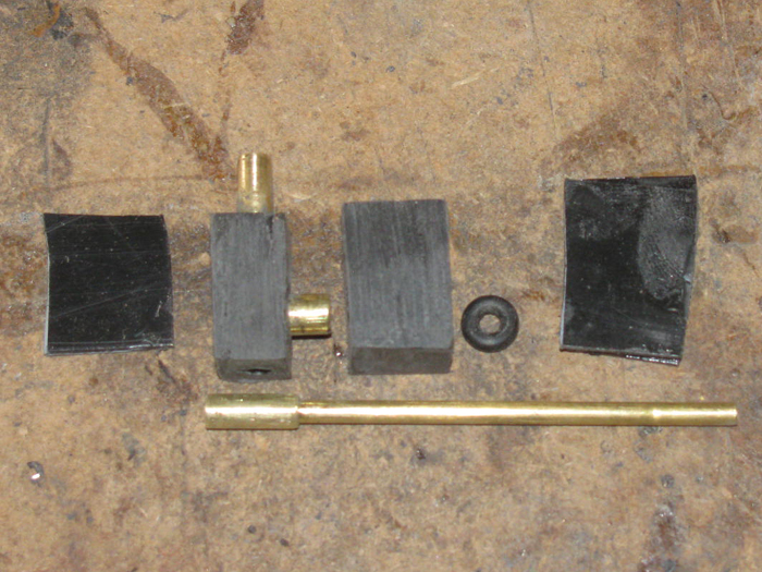
Start making parts.
First I will make an o-ring seal housing.
3 parts.
2 guides for the 1/8" brass tube.
1 for the o-ring. (slight compression on the sides and the diameter.
The o-ring housing was too thin with 1 piece of plastic and too thick
with 2.
So 2 it is.
After the cement cured, I sat down on my milk crate and started sanding
both sides of the plastic block.
Took my time checking thickness so many times.
Then I saw the o-ring starting to stick up above the plastic block.
I stopped here.
I can always sand more off later after the valve is complete.
Parts slid on to 1/8" brass tube.
The tube will be the actuator of the valve in the plastic block.
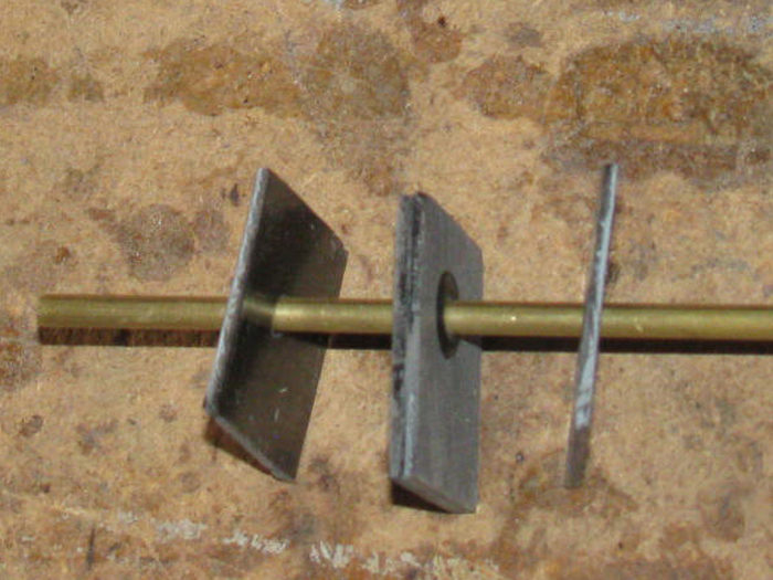
One side of the o-ring housing has been cemented to the center section.
The other side will be mounted with screws so it can be removed to
replace the o-ring if need be.
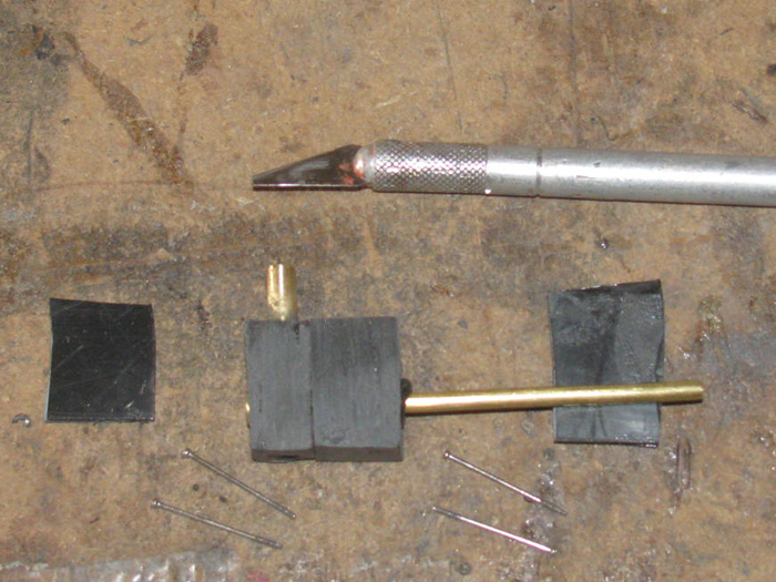
On to the valve body which will be 2 chambers with the vent valve between
the 2 chambers.
Made 2 blocks 3 layers thick from scrap plastic.
Did some measuring and drilling.
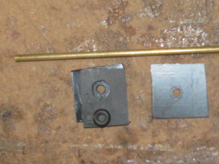
Left to right.
Bottom of o-ring housing.
O-ring housing.
Chamber from ballast tank.
Blank piece of plastic will go between the o-ring housing and intake
chamber.
The o-ring valve seal will set on this piece to seal the ballast tank.
Chamber from valve to exit hull hose.
Blank plastic to be the cover of the valve assembly.
The o-ring housing mounted to the intake chamber. (center)
To the right is the outlet chamber with the brass 3/32" brass tube.
(sorry about the clear tape reflection)
The glue on the outlet chamber and brass tubing will take 18 hours to
cure before I can work with it again.
August 26th ================================================
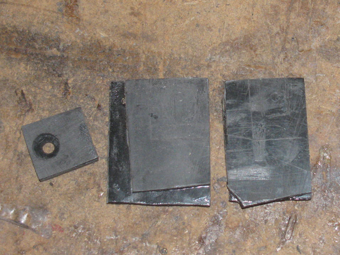
Parts for the vent valve.
Test fit on shaft.
Top of valve is on the right.
For scale, the o-rings are on a 1/8" diameter tube.
Well after test fitting and then some assembly.
I had to take it apart.
I took it apart 3 times.
Each time I noticed something was missing.
First time I realized I needed a plate between the 2 middle parts.
I had no place for the o-ring to seal against.
The plate will go between the right o-ring on the shaft.
It will be cemented to the valve body on the left.
The inlet and outlet bodies will separate.
Then I took it apart because I noticed I had no way to service the o-rings.
Okay, a little thinking was required.
Once I got it figured out, I need the valve body to separate in 2 places
to get to the o-rings.
The left plate will be bolted on to the inlet valve body with no glue.
Then the plate on the right will be glue to the outlet valve body.
I am going to look for some very small diameter bolts which I know the
hardware store has but they need to be 1" long.
If I can not find 1" long then I will use bolts or screws from each
end of the valve body and fasten to the plastic.
August 28th ================================================
I was not in the shop yesterday but for a few minutes.
I tested the valve.
I works!
But I think it is too big and I can not get it up high enough in the
cylinder and may not empty the ballast tank completely.
May leave 1/8" in the top of the tank.
So, I have another idea to try.
The valve will be a straight through with no step in it.
And it will be less complicated.
I think I can make it out of 2 brass parts, a plastic body, spring
and o-ring.
I have other things to do today but before I get to them, I will glue
up the plastic sheets pieces for the body so they will be ready to drill
later today or tomorrow.
-------------------------------------
Got in the shop for a few more minutes.
I had started the brass valve earlier today out of several scrap pieces.
Looking at it now, I can see making 2 different valve pieces.
Sort of like a needle valve and a slide valve.
Beings the brass pieces are long enough, I plan to make both valve types.
I cut up several plastic sheet squares to build up the valve body.
Not going to do any assembly this evening.
Just not up to it.
But first thing tomorrow morning, I hope to build both new valve bodies.
Today, I got a letter confirming my next surgery on my eye. (in 2 weeks)
The other eye.
The first on went very well.
This building with just 1 eye makes everything harder.
August 29th ================================================
The slide valve is coming along nicely.
The slide itself had been measured and trimmed to length.
The upper valve body has been shaped and cut to length for the slide.
When the slide is up, the valve is closed.
My original plan was to have the valve open when up but it required
more room at the top and I just don't have it.
It is easier to have the servo push up than pull down.
Up required no linkage just the servo arm hitting the control rod.
To pull down, the servo arm has to engage the control rod to pull down.
After thinking about it, the solution is to make a fork servo arm that
has the control rod in between the fork arms.
This way the arm will disengage and travel father to operate the micro
switch to run the air pump.
I have room for this system.
Below are all the parts to complete the slide valve. (except for the
4 little bolts. In next photo)
The valve body test fitting.
O-ring on right side and cap, that will be glues on on the left.
On the right is the bottom cap but it needs a hole for the control
rod.
Then shaping to match the upper body.
The outlet brass tube has been installed. (sticking up)
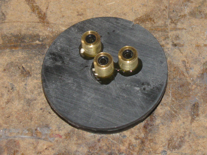
While the cement cures, I disassembled the original end cap.
I needed the main motor with gear box and the 2 servos.
I also took the plastic mounts which will make it easier to re mount.
Now I have a bare original end cap with the holes for the main shaft
and 2 servos.
Using as a pattern, I drilled the new end cap for the through cap seal
fittings.
I checked them first.
They do not leak.
Here are the main motor with gear box and the 2 servos with control
rods.
I can see one of the seals leaning so I put the assembly in the vise
to hold the seal fittings tight and straight while the glue cures.
The motor to shaft connection is interesting.
It is just a short piece of fuel hose slipped over both shafts.
The hose is in a recess in the end cap.
I can just see it between the end cap and motor mount.
(I was not sure about it, but I can say it has never slipped)
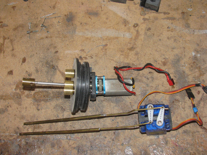
Tomorrow, I will finish assembly of the vent slide valve.
Then it will be time to start making the aluminum electronics tray.
(there will be 3 that connect together so everything slides in and out
of the wtc as 1 unit. (that's the plan)
September 2nd ================================================
I have been busy else where.
This morning, I had about 45 minutes in the shop.
I worked on the original motor mount to make it fit the new end cap.
This required drilling the mount holes just a little bigger so I could
use stainless bolts instead of steel Allen bolts that were rusty.
Once I got the stainless bolts through the motor mount and in to the
spacer piece, I needed to align the mount to the propeller shaft bearing.
To do this, I just push the motor shaft in to the rubber hose connector
and the short shaft out through the bearing.
Turn the motor gear to make sure it was straight.
Rough up the plastic end cap and the back side of the motor mount spacer
and apply plastic cement bond.
Hold for a bout a minute.
Then I put the unit on the short test cylinder piece and place an 8
pound weight on top of it to hold it down.
I went on to put the top plastic piece on the valve body.
A small problem came up.
A little sanding and filing and the top plastic piece fits.
I need to make a slight recess in the top to accept the piston.
The piston needed to go up an additional 1/32" to make the piston center
of the tube opening.
Now the top piece has been bonded.
This is all I got done this morning.
I think I will be done with the life stuff today and can get more time
tomorrow.
Still want to cut the aluminum electronics tray so I can start mounting
all the equipment.
The temperature is going to go up over 100 and higher the next few days.
So time in the shop may be short.
September 3rd ================================================
Out out to the shop early, only to get tools to work on the house cooler.
The cooler started squealing which is the V-belt.
Tried to adjust the tension and the bolt was so rusty that no wrench
would hold it.
Time to remove it and replace it.
Drug my Dremel out and ground a slot in the bolt head.
Got the a big screw drive out of the tools hsed.
Ground the slot wider to accept the screw drive.
With a 7/16" on the screw drive square shaft, I was able to rock the
bolt back and forth until I got it out.
Found a new bolt.
Got he liquid wrench out and retapped the welded in nut.
With the new bolt I can adjust the tension on the V-belt as needed.
Even made a squre tube steel adjustment bar.
I can slip it in between the fan cage and motor housing and move the
motor in and out on the adjustment frame.
Moving it was not a proble.
It was holding it there while I tightened the bolt.
The is done.
----------
In to the shop and back to the slide valve.
Put it together and tested it.
Now, what?
The slide works fine until I put the o-ring in and cover it.
Took it apart several times trying to see the problem.
Found it.
Turns out that when I glue the parts together and put them in the table
vise to put pressure on the parts, the glue makes the plastic soft enough
that it spreads under pressure.
When I put the cover plate over the o-ring, the o-ring was moved off
center of the slide valve shaft.
I took my exacto knife and trimmed loittle by little of the plastic
away from the o-ring retaining plastic.
Basically making he o-ring hole oval in shape.
But I only need the top and bottom of the o-ring to be in contact to
seal, the over size hole is not a problem.
I opened it up 3/4 of the way around the housing.
Now the valve is ready to close up and mount to the ballast tank end
cap.
Well maybe not.
I have to lay out where the servo will go and the micro pump switch.
I had been placing it vertically and horizontally to try to make it
fit.
I set everything down to move laundry to drier.
Came back and looked at the parts on the bench.
The servo had turned to about 40 degrees on the end cap.
The micro switch turns as well but not as far.
Okay.
All the parts are laying on the ballast tank end cap and there is room
around the parts.
Happy accident.
I made a paper drawing before moving the parts.
I need to build up some plastic mounts to hold the servo and mirco switch.
More curing time involved.
Late last night I was watching youtube videos of machines made to solve
problems. (third world fixes0
I saw a part on a machine that made me think of how to make the snorkel
parts for botht eh Gato and GW.
Time to make more plastic pieces to make these snorkel heads.
I have snorkel head valves before but I just could need a good seal
with only a small foam float doing the work.
So, I will be making more test pieces and see if what I saw will work
in this small of a version.
------------
Good news.
I received notice that my eye surgery is still on for Sept 15th and
pre op started next week.
So I may wait until after the surgery to try making these small parts.
------------
I cut several plastic pieces but I did not start assembling them to
make the snorkel heads.
I did work a little more on the sliding valve.
Working with the Exacto knife tip is not easy with 1 good eye and no
depth preseption.
I went slow and cut away a little more plastic so the o-ring could
move from side to side in all directions.
Making sure that the o-ring side stayed on the cover plate and not
move over the control rod hole.
I took me a bit but I got it.
The slide moves smooth and easy.
The micro servo will have no problems moving the side up and down.
(up will have a spring to keep it up in place)
The servo only pulls the valve slide down to vent the ballast tank.
No wind so far and the temp has gone over 105 F in the shop.
I am done.
I think I will go make a detail drawing of what I think the snorkel
head should look like and the peices to make it.
Or maybe it's time for lunch.
YEP! that's it.
September 4nd ================================================
Here are parts for the snorkel head.
I am making 2.
Top is the 1/8 ID breathing tube.
Next is the valve check valve. (1 on each end of the 1/8" brass rod)
Below that are 2 valve cylinders which the check valve will go in to.
Bottom are lots of plastic pieces to build up the snorkel head body.
SOme parts have been glued together and are in the vise under pressure.
September 5th ================================================
The brass check valve needles are made.
The brass tube sleeve for the brass needles are made.
The plastic valve bodies have been drilled and shaping has started.
The plastic piece that has the air channel from the inlet to the outlet
have been made and bonded to the valve body.
Waiting for bonding to cure to move on to installing the outlet sleeves
and the inlet brass tube. (needs to be measured to fit inside the sail
and exit at the bottom enough to put a 90 degree turn on it.
A plastic block will be made and then drilled to accomplish the 90
degree turn just under the missile deck and above the hull.
The second valve work has stopped.
I will continue on it when I get the Gato back on the bench and can
measure the conning tower for fit inside.
In the photo there are 2 snorkel valves
The left one will end up in the Gato, I hope.
This is the one the work has stopped until I get the Gato back on the
bench.
The right valve is going in the George Washington.
The sail is so small, I hope it works.
On the left valve body you can see the air channel from the intake to
the outlet.
Just needs to be covered.
The right valve body has the intake brass tube in place.
The needle valve is where it will enter the sleeve to stop air flow.
The sleeve will be glued and pushed in flush in to the body.
It will stop short of the air channel.
The needle valve point will stop when it touches the top plate of the
valve seen here laying down next to the valve body.
There will be a foam block with a hole through it to slide up and down
the long brass tube.
The needle will be mounted in to the top of foam so it goes in to the
sleeve tube.
I also think there will be 2 pieces of plastic along side the foam
to keep it from rotating away for the needle valve sleeve.
It depends on whether it fits up in the GW sail.
Time in the shop is over for today.
As I left I looked. 106 F.
I think that's enough for me.
September 6th ================================================
Snorkel head valve.
Foam float testing shows I have plenty of extra buoyancy.
I could cut 1/2" off but will wait to see if I can get it all in the
sail.
The valve check valve pin is glued in place in the foam block.
Valve open.
Valve closed.
Next I need to fit this in to the sail and figure out a way to mount
it so it does not move.
--------------------------
I decided to face my fears.
Painting. (I hate painting)
Start by marking the waterline by leveling the hull to the waterline
marks I wrote down for bow and stern.
Make a wooden block to hold the pencil to the marks.
Trace the pencil around the hull.
Tape off the center of the upper hull not to be painted.
I thought I would try using white first and light gray second spray
paint from 4 feet.
It acutally covered more than I thought it would.
Touching the paint, it feels rough.
I think that's good.
I may be able to use a cloth to rub some of the paint off to let more
of the bottom red and upper black show through.
IBy hand rubbing it I can make it streak.
I might even use 220 wet/dry sand paper to streak it.
Inoticed I got the rudder tape crooked.
Will have to fix that when I get to the streaking.
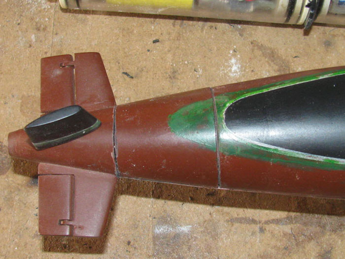
I used a green with white to lighten it up for the growth line and brushed
it on to make it not straight and perfect.
I pulled the tape and place the deck and sail on the hull for a look.
Yea, I am going to try removing some of the below waterline paint.
But I am not unhappen at this point.
I do not expect much from me doing any painting that is not 1 color.
Today the heat has come even earlier than yesterday.
105 F at 9:30am.
September 7th ================================================
I sat down on my wooden milk crate and started in on trying to soften
the white and gray fouling paint.
It all feels like over spray.
Paint seems to be just sitting on the hull like dust.
Using a rough rag, I wiped down the hull to see if the paint would
come of.
Some did but not enough.
I looked on the bench for some used sand paper.
Found some 220 wet/dry that has been used for a couple of years on
flat parts.
I lightly sanded in vertical motion.
Taking my time, it started looking good.
I want to see the black and red under the fouling.
I think I have what I want.
I can always do more sanding.
I worked on the upper rudder to fix the bad waterline.
I taped a correct waterline on the rudder.
I scraped the green paint off and sanded the upper rudder.
Applied new black paint.
Removed the protective tape and paper.
After it dries, I will paint the green back on.
Hull after sanding
Looks bright which it is not.
Must be the flash on the camera.
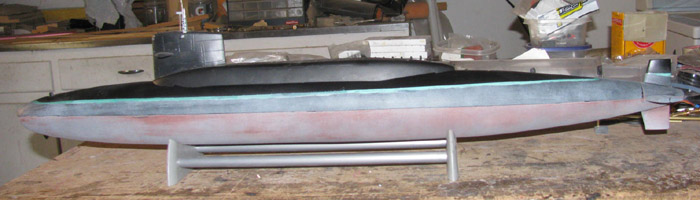
Took the boat outside to take another photo.
This looks more like what I see in the shop.
Now for bad news.
I took the sail off the missile deck to measure for the snorkel valve
and float.
Set the sail on the work bench expection it to sit upright.
I was wrong.
The sail fell to the floor.
Now I have another project to work on.
September 8th ================================================
Had an idea to fix the sail.
First I got down on the floor with my flashlight to look for the piece
that broke off the sail.
No luck at all.finding it.
So I will make a plastic piece to put in the sail to back up the repair.
I cut a 1/2" x 3/4" piece of 1/16" plastic sheet.
I flat sanded it on the bench to reduce the thickness of the piece.
Got it down to about half the original thickness.
Time to shape it.
I got the soldering iron out and heated the piece of plastic.
I slowly bent the piece in to a 90 degree angle.
The piece and wrapped it around the Exacto knife handle giving me a
curve of about 1/2".
Ths was close to the front of the sail curve.
I glued a piece of plastic to one end ot the bent piece.
This should give me a little on one side of the sail, the nose and at
the top.
After it cured, I sanded the top and edges to get a smooth curve.
A couple od test fits up inside the sail and I got what I wanted.
The piece fits tight up in the sail to all three surfaces.
I use my thin CA glue which has turned in to medium thick to cover the
inside of the sail around the hole and break.
Slipped the part up in to the sail and pushed it in to place with a
brass rod.
Slid it about to make sure to get CA on all the surfaces.
With the brass rod, I put CA on the edges of the new piece of plastic
to the sail.
Looked it over and when this cures, I should be able to use red auto
body glaze to finish off the outside.
Then detail the windows.
I think I originally tapes off the sail leaving the windows exposed
and just used silver paint to make the window.
This fix took about 15 minutes.
I am happy so far.
While out in the shop, I decided to fix a small error on the missile
deck.
The opening for the sail was cut a little big on one side.
I found a scrape of plastic, (a sliver) I glued it in place and this
morning I filed and sanded it to shape.
Did a quick light sanding of the complete missile deck and repainted.
I am currently doing small odd jobs on the GW and Gato.
I start the hospital stuff tomorrow to get ready for surgery next week.
Other eye. (the first eye turned out really well)
End of next week I should have depth preseption again.
---------------------
I have applied the first layer of body glaze.
It was a new tube of glaze so the glaze was soft, lots of liquid.
It pushed in to the gaps and seams very easily.
---------------------
I sanded the first glazing coat.
Second application of glazing.
This should be the last coat.
There where only a couple of low spots after the first coat.
Remember this sail is very small.
Top to bottom of the glazed area is less that 1.25".
The sail is less than 1/2" wide.
---------------------
Second glaze coat sanded.
The 6 windows will be taped off and painted when I get back from VA.
I also have to put some weld lines back on.
That is a matter of taping the lines and painting them on.
The thickness of the paint shows up nicely.
But first the sail needs to be repainted completely before any windows
or weld lines can be put on.
Taped off the masts and repainted the sail.
Second view of the sail.
Looks like a second coat will be necessary to cover the glazed areas
at the front of the sail.
The paint is glossy because I just painted the sail and it is not dry.
(the paint is flat black)
September 10th ================================================
First, yesterday went well at the VA.
I am cleared for surgery this coming Tuesday.
Got a late start in the shop.
But today's temperature is only 85 F compared to the weekend and Monday
which were over 114 F.
I am repairing the sail panel weld lines.
I know they are over size but I might as well continue the original
marks.
The heavy marks I saw under the paint have been sanded down and made
smooth.
I taped the weld line to be repaired.
A little body glaze applied with the Exacto knife tip.
Once it cures, I will sand down to the tape.
This seems to leave a nice looking weld line.
While the glaze cures, I will make a template to put the windows back
on the front of the sail.
I start by putting a piece of clear packing tape on the bench top.
Then I put blue masking tape on top.
This makes lifting the blue tape up without loosing the stickyness
of the blue tape.
I measured and marked the blue tape.
Cut with Exacto knife and steel ruler.
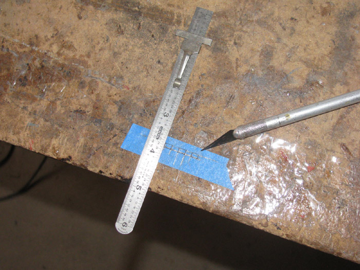
I now have a template to put on the sail.
I will paint through the holes.
I think I will use silver and then a light brush streaked light blue.
Let it dry and pull the tape.
Move the tape to the second location of 3 windows.
3 near the top of the front of the sial and 3 just above the sail planes
top surface.
--------------------
Glaze dried.
Sanding done.
Tape pulled.
I found 2 little low spots on the other side of the sail.
Looks like the original paint came up with the tape leaving these low
spots.
Sanded and filled with glaze.
Will sand a little later today.
Then it will be ready for repainting again.
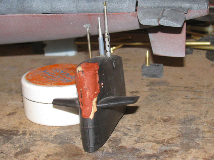
--------------------
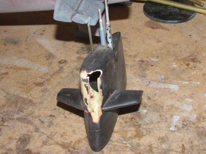
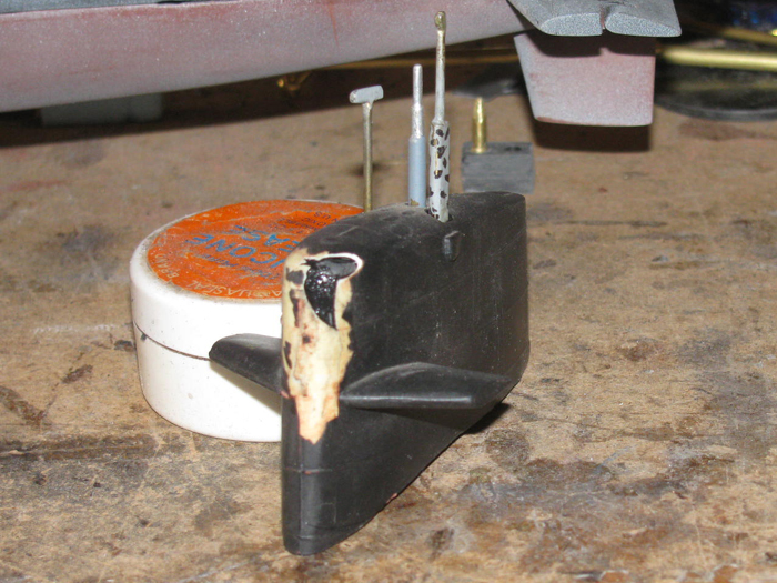
Repairs to the sail that was damaged when it fell off the work bench.
It fell because I thought it would sit upright and did not.
In this photo, I raised the back of the sail up to almost normal level
and the sail plane on the other side is leaning agaist the background paper.
I will let the paint dry over night and paint the windows on tomorrow.
--------------------
As you can see, I did not wait until tomorrow.
Tomorrow I will see if I can trim the edges of the first painting of
the windows.
Tone down the blue, though it is tranparent paint.
In the sun it may show up less.
I hate painting and I may not do much to the windows)
They are so small.
The brass pin sticking up at theback of the sail is 1/8" rod.
Side view.
|