Piece of 1/16" plastic that I have squared up one corner.
I also cut it to a length of 9.25"+.
I want a finished length of 9.25" for my tray(s)
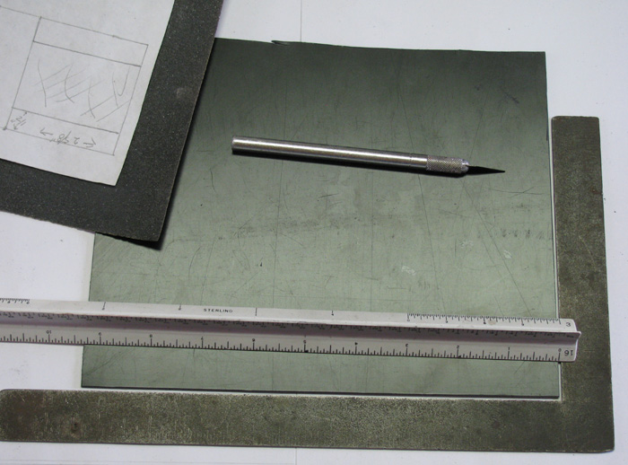
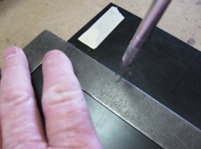
I am measuring and marking using my Exacto knife.
Just putting small holes where I want to cut the plastic.
Notice the tape on the plastic.
This marks the corner that was squared up.
Don't want to loose track of it.
Causes problems when I do.
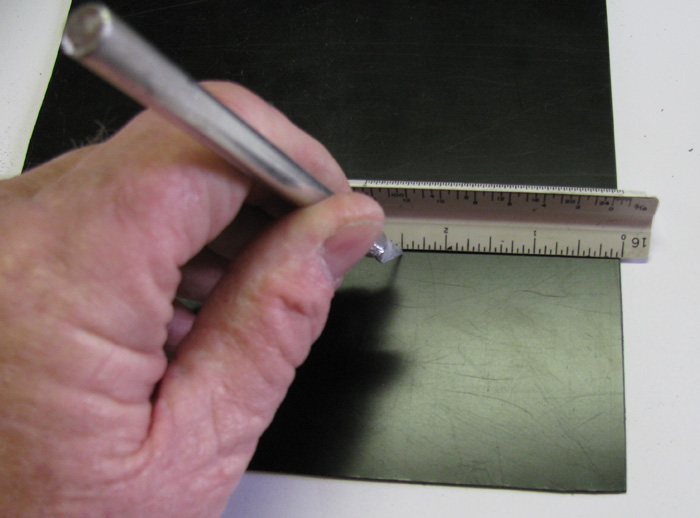
Using steel straight edge I am scribing the cut lines with the Exacto
knife.
Now a tip.
If you use the cutting edge of the knife, it can and will wonder way
from the straight edge.
Doesn't seem to matter how much attention you give it.
The trick is to use the back of the knife, not the cutting edge to
scribe the line.
If you turn the blade just a little to track towards the straight edge
it will stay there.
It took 5 passes with the back side of the knife to cut a little more
than half way through the 1/16" plastic.
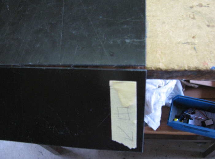
After scribing the. I move the plastic to the edge of the bench and
just pushed down and snapped it on the scribe line.
Nice clean break.
A little trimming to take down the plastic edge that rolled up during
scribing and it's done.
As you might know if you have been following the progress on this build,
I am using the Skipjack to see how things fit and will be using it as a
guide for two other boats.
The tray has been test fitted in the cylinder and I like the way it
looks and how everything fits on it.
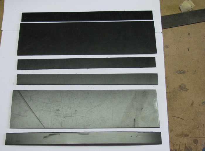
So, the next photo shows the other two tray parts after cutting them
to size.
The 4 narrow strips are to reinforce the tray edges.
Photos below.
Using the first tray to get measurements from I marked the second and
third tray.
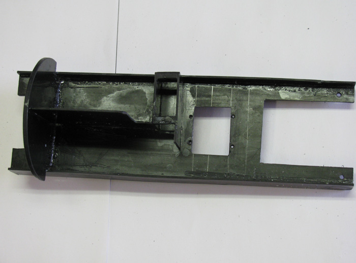
Here the motor recess has been cut out and I am working on the hole
for the rudder and rear planes servos.
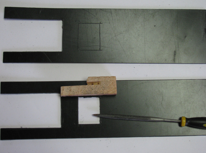
Test fitting the servo.
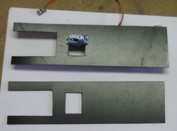
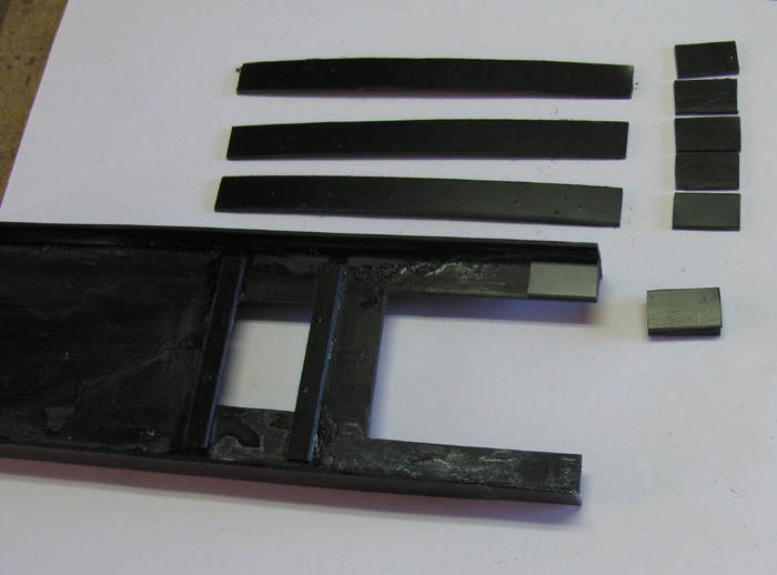
The two trays I just cut out are at the top of the photo.
The bottom one is the first tray built by trial and error.
It was wider but didn't fit in the cylinder right. Needed it lower.
Below center line.
Here you can see the two side strips for strengthening.
The tray is going to be have about 1" in length removed.
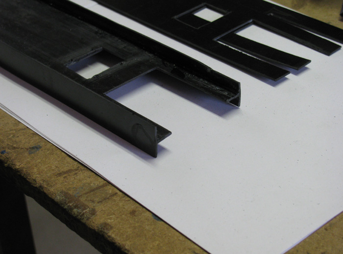
Cut the tray to accept the ballast pump.
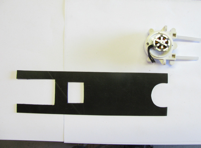
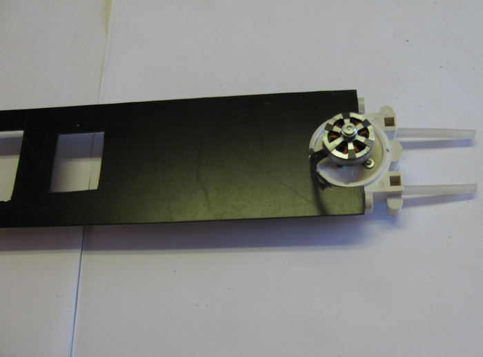
Ballast pump test fitting.
Works out that the bolts will enters from the right side center of
the tray deck.
I will cut some small pieces of plastic to stack and glue two on top
and two on bottom of tray.
That ought to do just fine.
Adding re enforcement blocks.
Two for the servos screws.
Eight for the pump bolts. 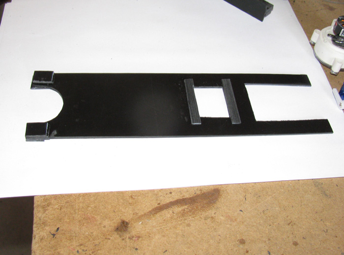
Needed some blocks for mounting the tray to the motor bulkhead.
I cut some 5/8" strips using the Exacto knife, scribing lines until
I could break them straight. (top center)
Using scissors, I cut the strips in to 3/4" long pieces. (top right)
I will mount one block on each side on the bottom of the tray to give
it more strength for the attachment screw to go through.
I will bond 4 pieces to make up the blocks that will mount on the motor
bulk head that the screw will go in to.
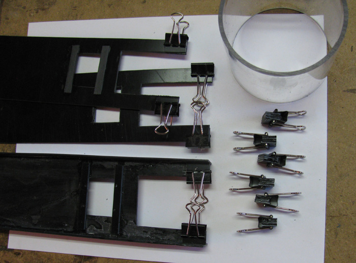
Here the two pieces have been cemented to the three trays I need.
Also the 4 piece blocks can be seen held together for curing with paper
clamps.
The short cylinder is the cut off from the Skipjack cylinder.
It's 3" long which makes it very handy to check fit with the various
parts as I go along.
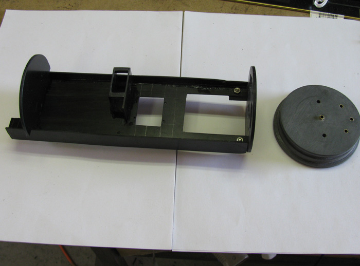
The tray with the sail planes servo box in place.
That's it in the middle of the tray.
I needed to raise the height of the servo to go over two other servos
and the motor.
The right disk is the motor and Mast Gizmo servo mounting bulk head.
The left partial disk is the for aligning the tray in the cylinder
and the ballast pump ESC will be mounted on this bulk head.
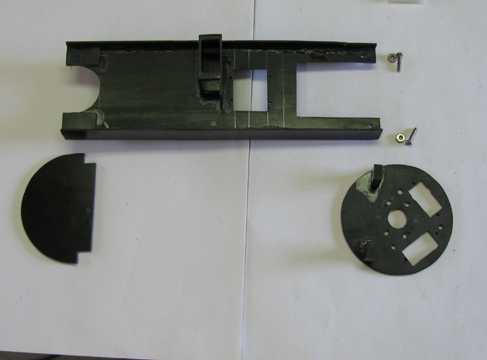
Bulk heads in place. (temporarily)
I needed some where to mount the FailSafe board and the Auto leveler
board.
I decided that I could place a piece of plastic sheet between the Rx
and the main motor ESC.
I made sure there was room for both, including for cooling around the
parts.
While setting parts on the tray, I found I had made a mistake in measuring
for the rudder control rod through the rear end cap. It was only 1/16".
But this caused the rod to drag on the motor can. Not acceptable. So I
filled the rudder and the stern plane control rods through the end cap.
I'll need to let this cure for a couple of days. I did this once before
and only allowed a day to cure. When I drilled the new hole, the glue was
still wet in the center. What a mess that was. My plan after remeasuring
everything with all the equipment on the tray, is to move the holes over
3/16". I have enough room to move the servos over to keep everything straight.
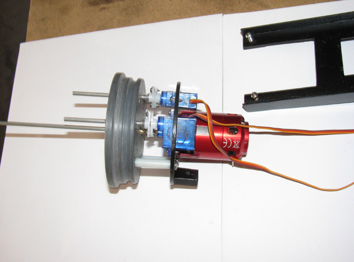
Assembly of the electronics tray begins.
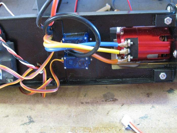
Two Mast Gizmo servos mounted to rear tray bulk head including their
winch shafts.
Main motor mounted to rear bulk head including the propeller jack shaft.
Rear bulk head mounted to rear end cap including the 1" nylon tubing
spacers.
These nylon tubing spacers are hard nylon. They don't bend.
I threaded the bolts 1.2" in to the in to the end cap.
Tray bolted to rear bulk head.
You can see the bolts in the photo above. Nuts are on the bottom.
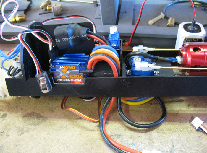
Three servos mounted to the tray.
Rudder, Rear Planes and Sail Planes.
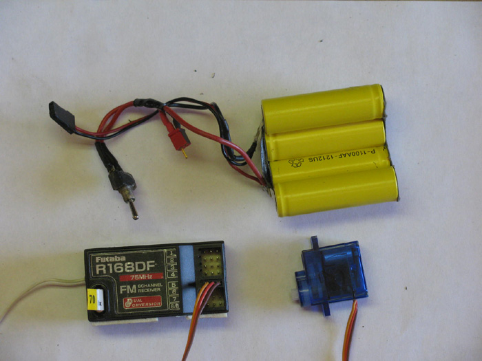
Rx is in the photos.
I tested all servos and they all work and work in the correct directions.
The sail plane servo is a bit noisy so, I may replace it.
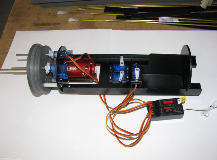
Rx mounted in place with double face foam tape piece.
Main motor ESC mounted with double face foam tape piece.
Ballast pump set in place but not mounts as I need to make holes in
the centering bulk head for wires.
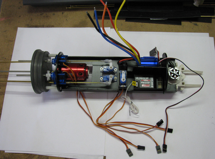
The ballast pump ESC will be mounted with double face tape on the pump
side of the centering bulk head.
Yes, there's room between bulk head and pump motor.
Lost Signal FailSafe will be mounted with double face foam tape on
the dividing bulk head above the motor ESC.
The Auto Leveler will be mounted with double face foam tape on the
dividing bulk head above the Rx.
Important numbers.
Length from front of rear end cap to forward most of ballast pump.
(not including hoses) 10 1/2"
Width of centering bulk head. Just aft of the ballast pump. 3
1/8"
Width of tray. 2 5/8"
There is room for the battery under the tray but I will probably move
the battery forward under the ballast tank container. My cylinder is 22"
long so that leaves me about 10" of empty cylinder forward of the electronics
tray to put a ballast tank, battery, Off/On switch and any thing I might
have forgotten.
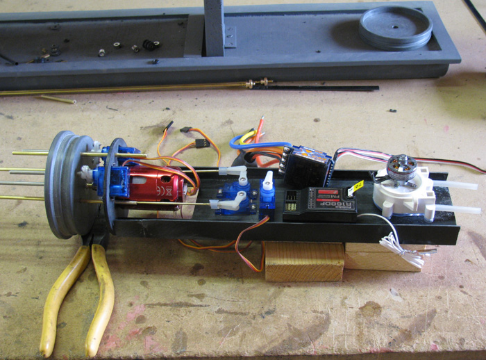
Here are a couple of photos showing the progress with the tray.
Tray is not glued to motor mount bulkhead....yet.
Main motor is mounted.
Two servos to operate mast Gizmos mounted.
Rudder and Rear planes servo mounted.
Sail servo set in place, not mounted.
Rx set in place, not mounted.
Main Motor speed controller set in place, not mounted.
Ballast pump setting on tray, not mounted. The pump will be fitted
in to the tray with the motor above the tray and the pump below the tray.
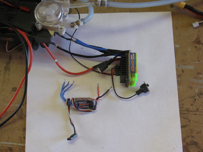
The FailSafe board and Leveler board are not in the photo. Due to the
leveler needing to be vertically and horizontally leveled, it will be mounted
on a plastic piece mounted between the Rx and speed controller.
There is also a speed controller for the water pump motor but it is
very small. Smaller than either the Failsafe or Leveler.
It can be mounted any where. There will be more than enough room next
to the pump motor once put in place.
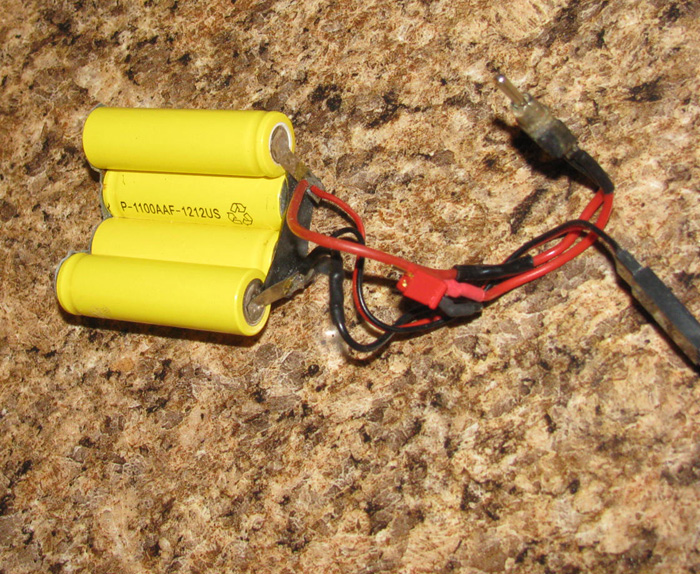
Battery. It will fit under the electronics tray and it will fit under
the ballast tank holding tray.
Perspective. This electronics tray is a little less than half the cylinder
length so there is plenty of room for more. Don't for get there will be
an On/Off switch. Not sure it it will be at the back or front. Leaning
towards front.
The tray itself is still about 1" longer than it needs to be. Will cut
it after all equipment is mounted. There's a stiffing/centering bulkhead
that will go on the end.
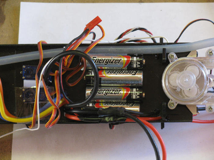
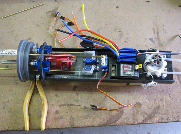
This photo is of the first tray while seeing how everything will fit
on it.
I have decided to cut the tray 1" shorter.
That's next.
Then I will cut a hole for the pump and make mounts for it.
I have double face foam tap for the ESC and Rx.
The right servo is for the sail planes.
In the photo it is just sitting there and too low.
I have made a plastic box to put the servo in and raise it so that
it lines up with the rear cap seal exit.
It will be braced with a plastic piece that will have the FailSafe
and Leveler mounted on the sides above the Rx and ESC.
Yes, it all fits.
There will be lots of wires. They should fit under the tray and come
up where needed.
 |