Last time out with my Akula II submarine, I ran it so long that the
BEC cut main power to the propeller motor.
There was no wind that early in the morning.
I had no where to be that was important so I decided to just sit it
out until the boat came to shore.
The real question was which way would the wind blow when it came.
The boat was about 150' out from shore but if the wind blew off shore,
the boat would go across the lake and it was about 3/4 mile around to the
other side.
I got lucky because there is an aerator out about 175' out from shore
and this causes a very slight current moving sort of towards shore at about
90 degrees from where I was using the park bench.
Using trees on the far side of the lake, I could see the sub moving
about 10' every 15 minutes and in the right directions.
Then I noticed the leaves on the tree above me where starting to move
slightly.
Good news, the wind was in the correct direction so far.
From the time I lost main power until I could reach my sub with the
antenna I removed from the Tx.
It took about 1 hour 45 minutes.
Got to sit in the park and enjoy the morning. (A bit of stress)
Everything turned out just fine.
This would not have been a problem if I had taken a second boat with
me.
I did not.
I also was running alone because this was not a group day to run.
So there where no other boats of any kind to help push the sub back
to shore.
While sitting there watching my sub slowly drift towards shore, I thought
I needed to bring a second boat every time I go out.
Also thought I might build a rescue boat for just this sort of thing.
Have it with me for me and any one else who might need rescuing.
There have been others that have gotten stuck off shore and needed
a push.
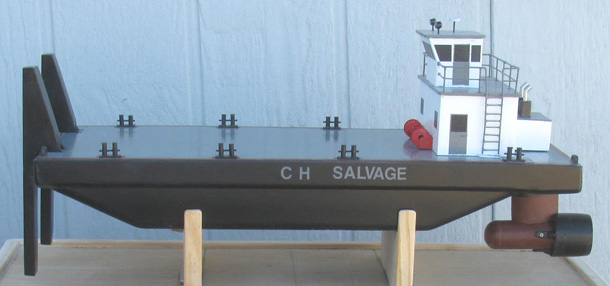
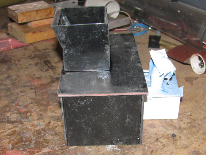
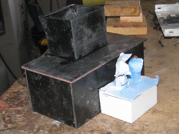
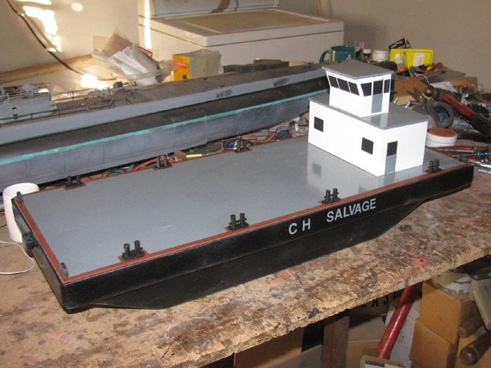
I posted this adventure on Sub Committee and got a response from Greg
with attached photos of his rescue barge.
Very simple design and much like I was thinking sitting in the park.
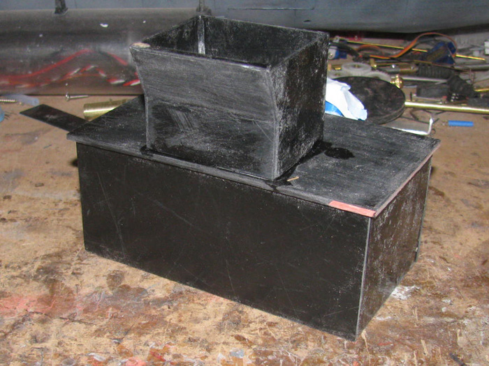
A cement mixing box, square in shape and rounded up are both ends.
Greg made me an offer of a hull like his that I could not refuse.
It arrived with in a few days. (Greg, Thank You)
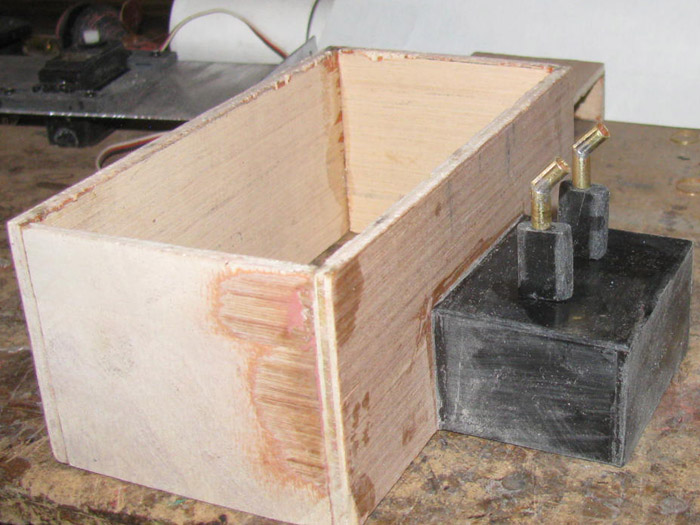
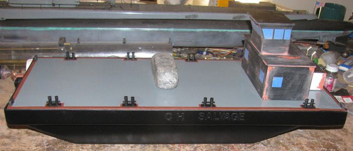
So here is where the build will start.
====================================
The building of a Rescue Barge.
November 14th =================================================
I looked through my parts box and I think I have everything but a propeller
the size I want to use.
I have spare sub propellers but they are either to big or too small
in diameter.
I have ordered parts.
Couple of propellers and a couple of dog bone universals. (spares)
I have thought about it.
A propeller with 2 rudders or a Pod hanging below the hull with the
motor in it.
The steering linkage is simple.
I can get about 100 degrees from a 60 degree servo using 2 wheels with
notches and cable.
I am going to start building a propeller pod.
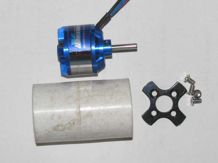
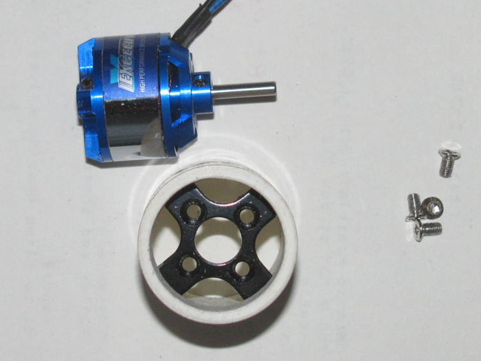
I have a brushless motor that has lots of torque and is small in size.
It will fit inside a 1" plastic pipe connector.
I do have to grind out the inside about 3/32" to get it to slide in.
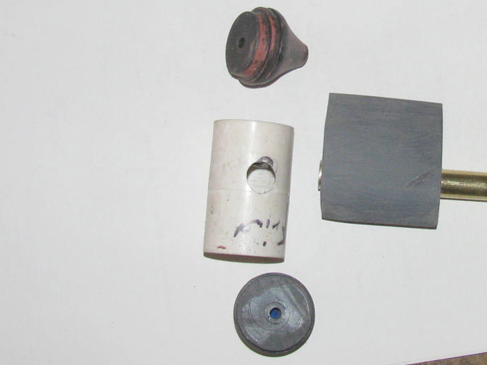
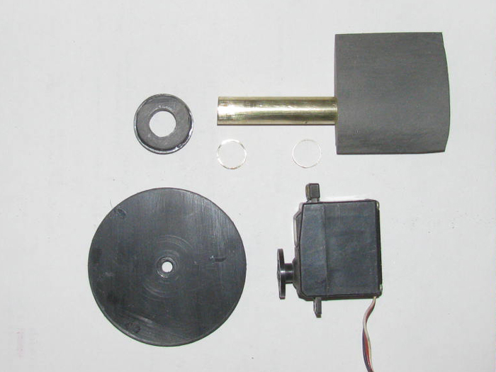
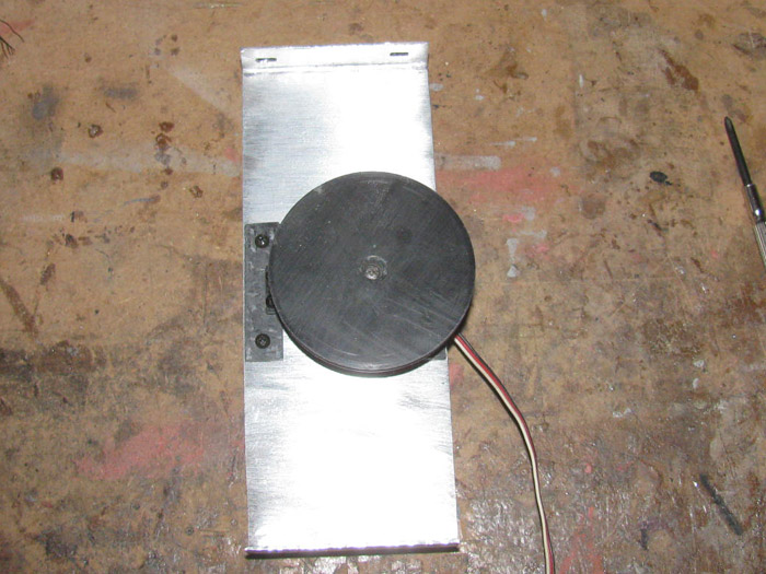
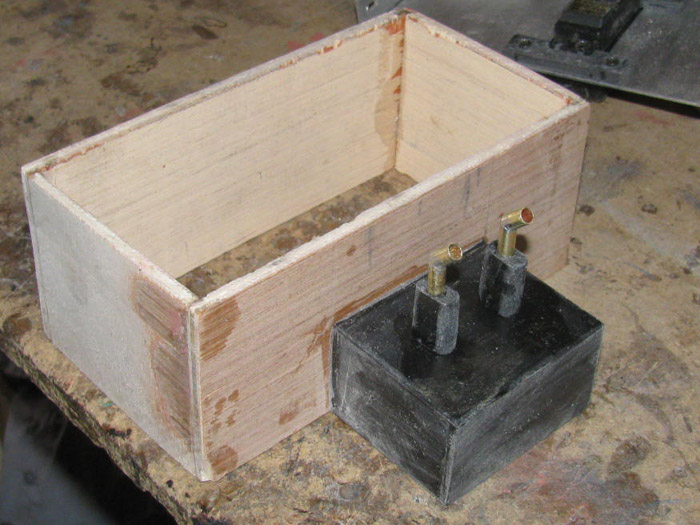
Here is the brushless motor.
The mounting bracket that came with the motor cut down to fit inside
the connector and mounting screws.
The 1" plastic PVC pipe connector.
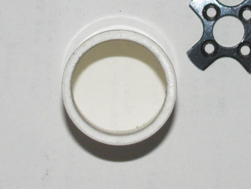
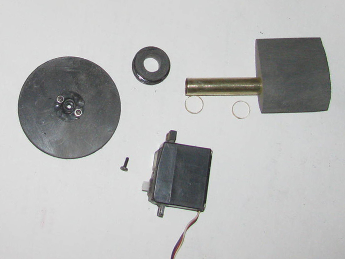
Before grinding on the PVC connector.
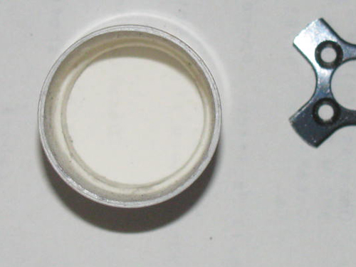
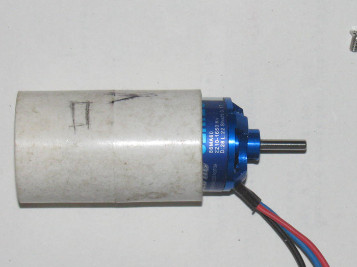
After grinding.
I made a shoulder for the mounting bracket to sit on.
I will epoxy the bracket to the connector.
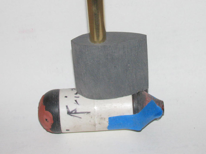
Bracket pushed in to check fit.
Took a couple times to get it down to size.
The motor is currently in backwards because the wires are pain to get
in the connector and through the bracket.
The wires will come up through a 1/2'" brass tube.
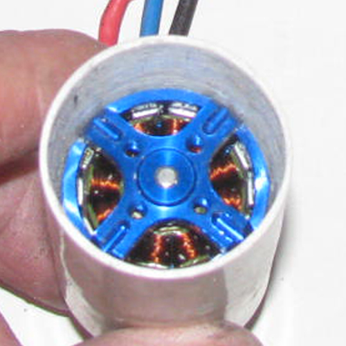
Motor mounted on bracket.
Pushed in to connector to check fit.
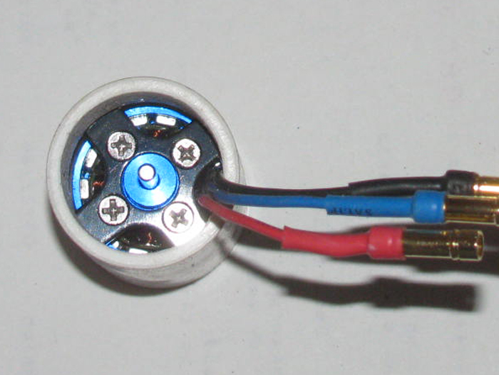
I will clean up the inside of the connector with sand paper.
Then I can epoxy the bracket in place.
Something to do tomorrow.
I have also cut a bunch of 1/16" plastic sheet square to make the front
of the pod and the rear shaft section of the pod.
The have been cemented up and are in the table vise.
I need to get a cup seal out of the parts box so I know how big to make
the tail of the pod.
I will actually wait until the propeller gets here to make the rear
section.
November 15th =================================================
I am going to turn the front of the pod drive.
Yesterday, I cut the plastic sheet squares and cemented them together.
Today, I drilled a hole through the rough center.
Put a bolt through the hole and put a couple of nuts on it to keep
it from spinning on the bolt.
Put in my drill press and got after it.
This is what I have after spinning.
There is a shoulder on the bottom of the part to slip in to the PVC
connector.
The rest was rounded to give it a better look and cut through the water
a little better.
The hole has been filled with glue and is curing.
I will continue shaping once the glue cures.
Here the front part is pushed in to the connector.
It is a tight fit so I may need to sand it a little more.
I want a slip fit and will put it together with a little silicone glue.
If I have to work on the motor, I can twist and pull these a part.
I marked it for 3 small screws as well.
Might use the screws instead and use silicone grease.
The connector is long and will be cut after I get all the parts made
and fitted.
The motor mount bracket with the motor on it have been epoxied in to
the connector.
I have plastic shims holding the motor centered in the connector.
I am using 1 hour epoxy so I will have to let it cure as well.
November 16th =================================================
Making up the plastic part to turn a tail cone for the motor pod.
This will be in two pieces so I can get to the cup seal..
Making is so I can get to the motor, the seal cup and propeller shaft
is the fun part.
I have how to do this in my mind.
Thought I would try to make a drawing.
A PVC connector for the pod body.
The blue is the brushless motor.
The red is the motor mount.
The green is the seal cup.
The gray are the pod body parts held together with stainless screws.
November 17th =================================================
Progress today.
I made the tail cone for the pod.
Even got the under cut curve I wanted.
While spinning the part in the drill press, I used my Dremel with a
1.5" grinding disk.
Then I used 200 wet/dry sand paper to smooth the curve out.
Next I will make the spacer between the pod and the tail cone that will
hold the cup seal.
I did not get to the space because I had to modify the nose piece.
After sitting over night, I guess the plastic cooled and shrunk a little.
The step of the nose that slips in to the connector is now very loose.
I built up the edge and will return it after it cures.
After looking at the pod test fitted, I did not like the look of the
nose.
It was too blunt, so I added 2 layers of plastic to the front so I
could reshape the nose a little.
I really don't know what it will look like until the propeller gets
here and I can place it on the shaft.
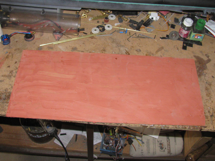
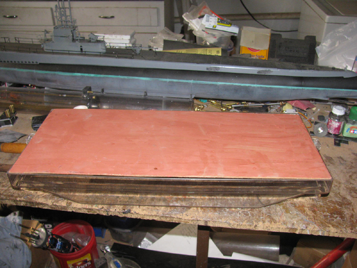
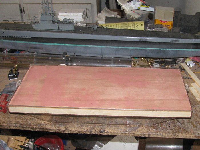
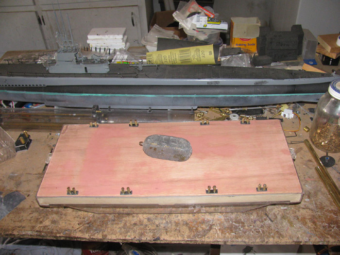
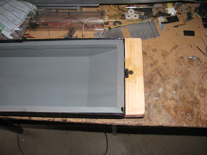
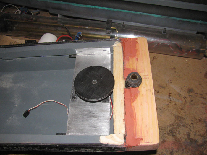
I looked through my wood pile and found some 3/16" thick plywood.
I will set it on the hull and see if it will make a good deck.
I will have time in the shop tomorrow.
Hope to get more done.
November 18th =================================================
Today, I worked on the tail cone spacer until it fit the tail cone and
connector correctly.
I took the nose piece out to the shop along with a Dremel, Exacto knife,
couple drill bits, several small files.
When I got in to the tool shed, I didn't have the nose piece. ? ? ?
I looked in the shop, the tools shed and the path from the shop to
the tools shed.
That nose pieces is nowhere to be found.
I looked for 10 minutes.
Okay, that is enough.
Cut some more plastic squares and glues them up.
I will turn the piece again later in the week.
Put this in the small vise.
I thought about cutting the plywood deck to size.
I made one more trip to the scrap wood pile.
I found a piece of 1/8 plywood that was 2 long and 3 wider than
needed.
I have measured and cut this to size.
Rounded the corners to fit in to the hull.
The hull is a polycarbonate electrical box cover.
Photos of that later.
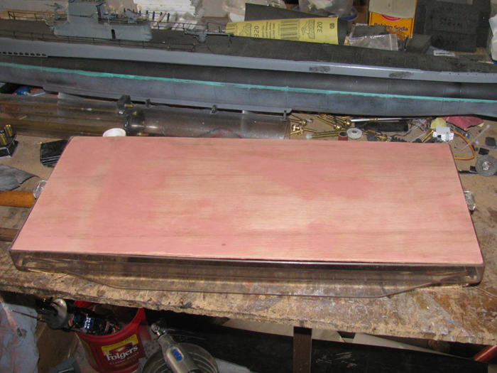
I glazed the deck to get rid of the wood grain.
I want a smooth deck look.
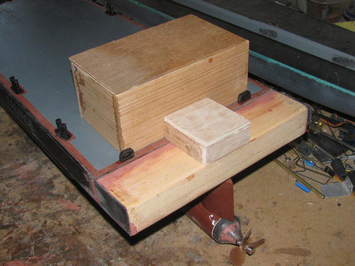
I cut some ¾ pine board to make a 1.5 extension to the stern
to get the motor pod will get in to clean water flow.
This extension will have ¾ bottom with 1/8 wood sides to match
the hull.
All the parts are cut and the gluing has started.
While the parts cure, I did a quick layout for the servo and steering
post down to the pod.
I plan to make plastic 2 pulley wheels to make the 60 degrees servo
move the steering post 190 degrees.
I have plenty of room to make this happen.
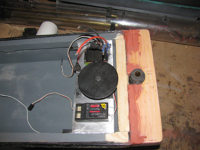
Remember, I need 1 Rx, 1 servo, ESC, motor and battery pack to make
this work.
I will have a second servo and hope to make some sort of crane devise
to get around the rescued boats.
May not be needed but time will tell.
I have foam to fill the hull leaving pockets for the equipment.
More than enough to keep the barge and even a rescued boat from sinking
should the barge hull flood completely.
=======================
I also am still working on the Gato cylinder cap.
I am filling a hole in the cap so I can re drill the bolt hole that
was in the wrong place.
This is slow going because I fill about 1/8 at a time and let cure
completely.
Then I add more glue.
I think I am on the 4th fill.
Hope this is the last.
=======================
More barge parts.
I have glazed the tail cone and spacer.
I have sanded the glaze down with 220 wet/dry sand paper.
This got rid of the cutter marks.
Making propeller shaft bushings to go in the tail cone.
Cut to length and roughed up so the glue will hold.
Here are the tail cone and the tail cone spacer.
The cup seal will go in the tail cone and the spacer will squeeze the
cup seal slightly.
--------------------------
Changes to the pod.
Room in the pd has become an issue.
I had to move the cup seal back in to the tail cone.
Shorten the front of the pod spacer that goes in to the pod body.
This is required because I need more room to make a connector for the
motor shaft and the propeller shaft.
I left room to drill a bigger diameter recess in the spacer.
This is why the bushing is short in the spacer.
(gold color represents shaft bushings)
At this time, I am not sure there is enough room.
Got to make parts to see what I can do.
Already tried to drill 1/16" wheel collars to 1/8".
Fail because I could not hold the wheel collar tight enough to keep
it from spinning with the drill bit without crushing it.
November 19th =================================================
Before going to the big city this morning, I was out in the shop.
Did a little more work on the stern addition that will hold the pod/rudder
through tube and the servo to control the pod.
This is a wood structure about 1.5" deep by 1.75" long and 9" wide.
I have 2 of the 3 sides glued together and will do the 3rd side in
the morning.
It will be fitted to the back end of the hull I have.
After completing in town stuff, I drove over to the hobby shop.
I picked up stainless 1/8" rod for propeller shaft.
Found a brass tube that will slide tightly in to the short test piece
of tube I took with me.
Got more 1/16" & 1/8" wheel collars.
A bottle of CA glue.
I am good to go once the propeller gets here.
I need it with the pod to determine where to put the pod and how deep
to put it.
---------------------
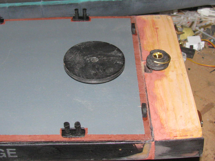
While driving to town, I thought about how to hold the deck on the
hull so it can be easily removed.
Either bollards or cleats down each side of the deck.
These will turn 90 degrees and hook under the deck in to wood beams
with slight notches in them to receive the latch piece.
I will see if I can find some already made before taking on making
8 of these.
November 20th =================================================
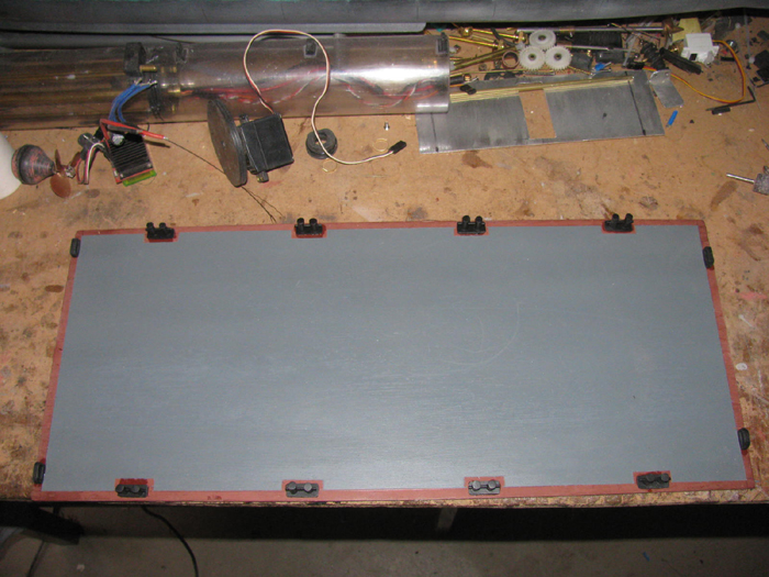
I am working on the deck and it's frame.
Deck cut and fit.
Sanded the deck surface and then applied glaze to get rid of the wood
grain.
Re check deck fit.
Sanded the glaze smooth.
The beginning of the deck support frame.
I want the deck flush with the top edge of the hull.
Main frame is shown in the hull.
I need to make a few shims to raise the deck up about 3/16" to be flush.
The shims will go under the frame seen here.
Maybe 3 per side and one centered on ends.
The corner shims will support both the sides and ends.
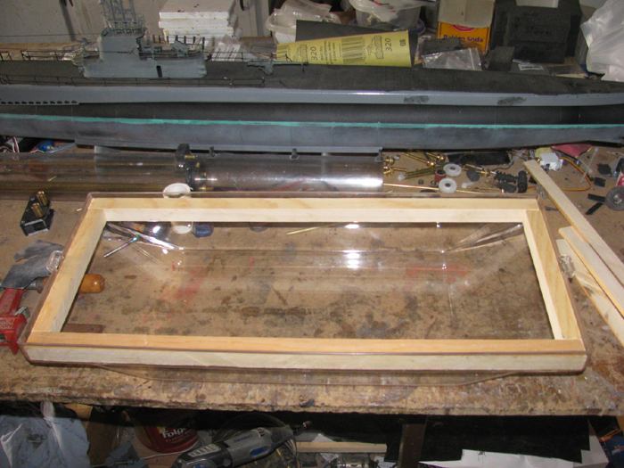
Deck fitted before shims added.
The shims and long frame pieces are cut to size.
The shims are being glued to the frames.
1 in each corner and 1 in the center.
All clamped together to cure.
---------------
Of course there is always this curing time.
Not to waste the time I have left in the shop.
I knew when I started I was going to detail the deck a little.
I thought 4 bollards on each long side would look good.
Found a photo I could scale and made dimensions for the bollards.
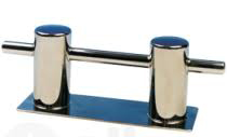
About 1/60 scale.
That happened because the 1/72 scale looked to small and the 1/48 scale
was too big.
Works out for the size of brass tubing I have in the parts box.
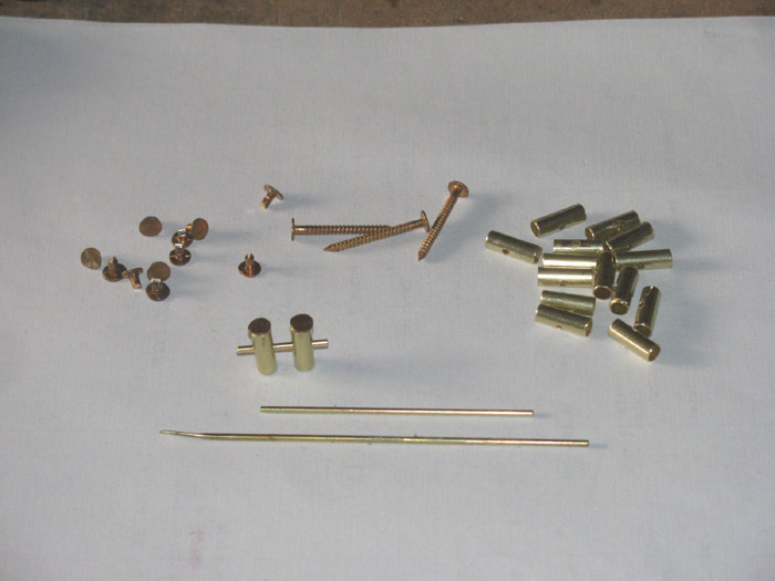
I got my wooden milk crate over by the bench and started cutting 9/16"
long pieces from the tubing.
Need 16 of them little . . . . things.
Tomorrow, I will drill each tube for the 1/16" cross bar per pair of
tubes.
I will make the 8 bollard deck plates. (plastic)
Found some bronze nails out in the tool shed that I can use the head
to top off the bollard posts.
Tomorrow, I can work more on the deck frame pieces.
November 21st =================================================
Made a jig so I could drill the 16 bollard tubes.
Cut bronze nails to tops and 1/16" brass rod for cross bar.
I am not sure I like the bronze nails on top.
The problems is they are not all round or centered.
If after I get the bollards completely assembled so I can handle then
after the glue cures, I will see if I can fit the look.
If not, I can take a pair of pliers and twist them out.
Fill with epoxy and sand flat.
Here are all 8 bollards with glue in side to hold the cross bars in
place.
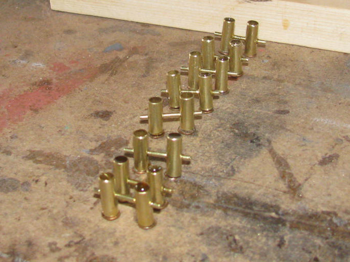
I probably should have made the deck mount plates before assembling
to hold the bollard post straight.
If I get 6 good bollards, I will go with that.
I can always make more later.
I have also worked on the wooden under deck frame.
Cleaned up the parts I made yesterday and made a couple of new parts
to add to it.
Worked on the stern extension some more, then realized I was going about
it in a way that was far more complicated than necessary.
I was building a box to add to the back of the barge.
I had made the bottom and 2 sides.
This morning I was going to make the top/deck part. when I realized
I made this more work than needed.
When I measured the needed depth I only needed to add 1/2" to the bottom
board.
If I had made the bottom board 1/4" longer I would not need the sides
and I could just add 1/2" thick board on top of it.
This would make the stern extension solid.
Okay, out to the saw and cut 2 boards.
Glue then together.
The only thing I will need to do is shape it. (all straight lines)
And drill for the rudder post.
A big DUH! at this point.
I prepared the deck for primer.
I have not decided if I want the deck red primer or light gray.
Got to look at more barge photos.
----------------------
Continuing today, I cut the plastic bases for the bollards.
Drilled them.
The glue I use takes 17 hours to cure and 24 to harden completely.
So, I took 1 bollard at a time and slipped the base on to the two posts.
This gives me the distance between the post.
With the glue still workable, I moved the cross bar to make it centered
between the post.
Did this 7 more times.
Moved on to the deck.
Looking it over, the bottom needs some glaze work on the cut ends.
Not much but enough to stop the wood from splintering.
Glazing done.
Took the pod nose out to the tool shed.
Did a little more turning on it to get a better looking shape.
Finished that and then filled the centering bolt hole with CA and baking
soda.
This will need a little filing tomorrow.
looked a barge photos.
Still not sure to go red or gray.
Simple fix is this.
Prime with the red so I can see it.
If I don't like it, then I can paint gray.
Time to start looking at barge pusher cabs.
While going through photos, I saw a crane barge.
It has a small cab at one end but it was two stories.
I think I will make a simple cab out of cardboard and look at it.
I have an idea for the push bars and part of crane on the deck.
Needs to be easy to work with a single servo.
Or I need to come up with a Rx with more channels.
November 22nd =================================================
Started working on bollards.
Cleaned the excess glue off and found that the glue is not completely
cured on some of the bollards.
This glue expands so, I will have to clean them again after they do
finish curing.
Sized the mounting bases.
Set them on the deck for a look.
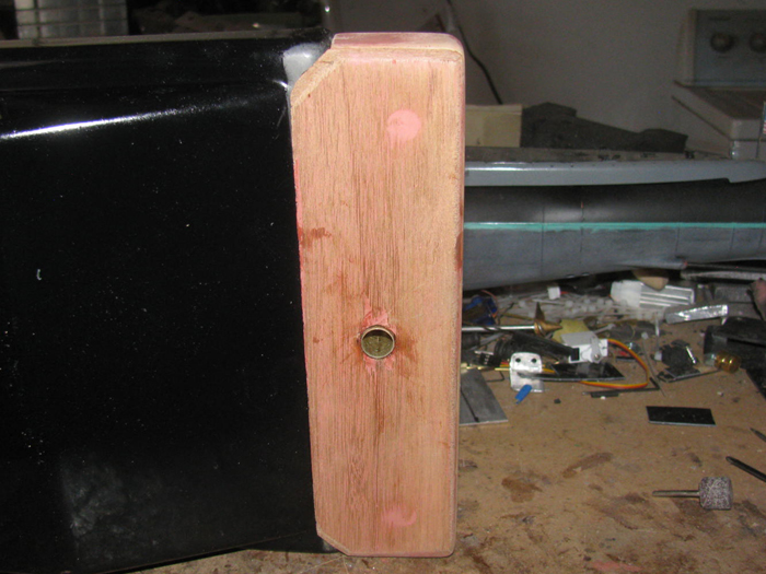
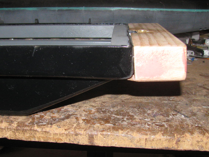
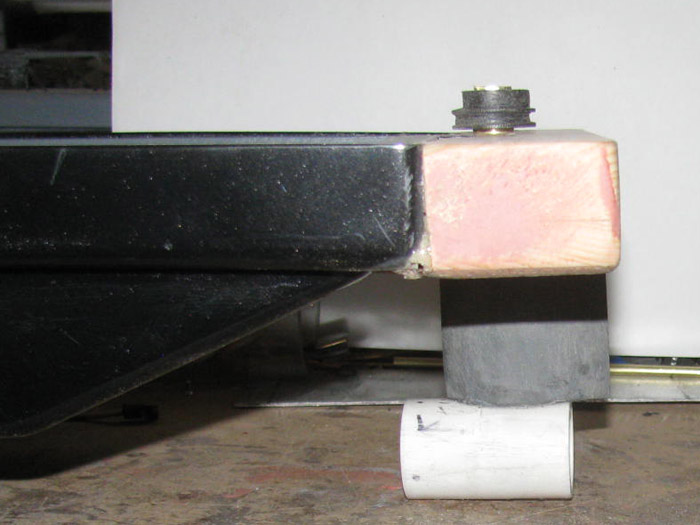
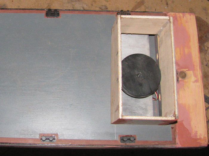
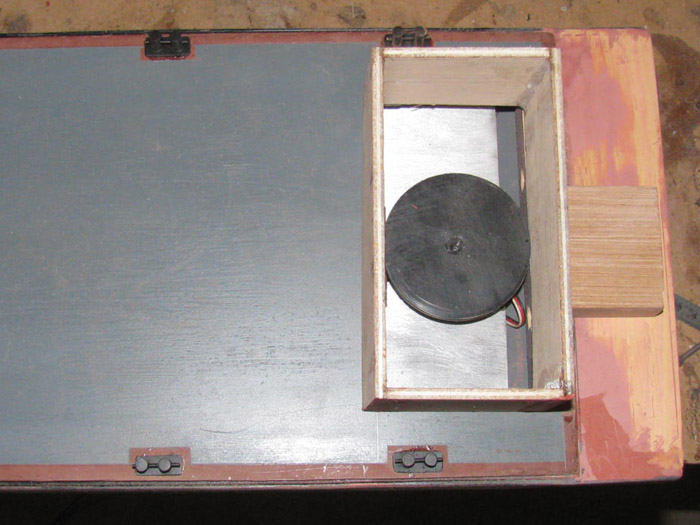
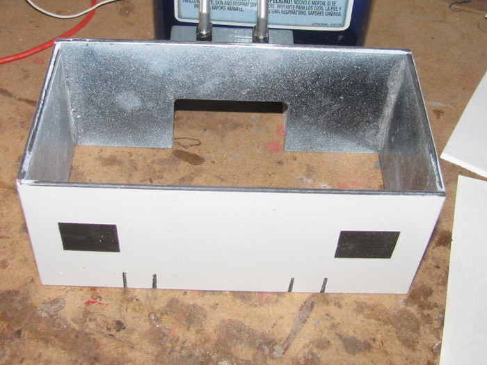
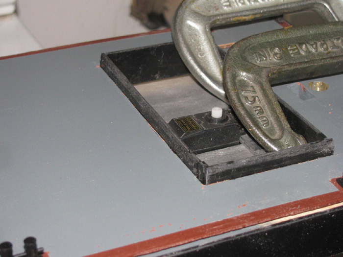
A side view which also shows the plastic electrical box cover being
used for a hull.
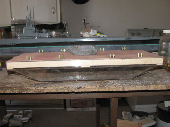
I cut wooden blocks for the extended stern.
Cut to finish size and then drilled 1/2" holes to lighten the block
up some.
Made sure I left sections for screws or bolts to mount the block to
the transom.
Glued the 3 parts together and put them in the vise with a couple of
clamps.
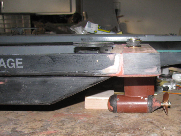
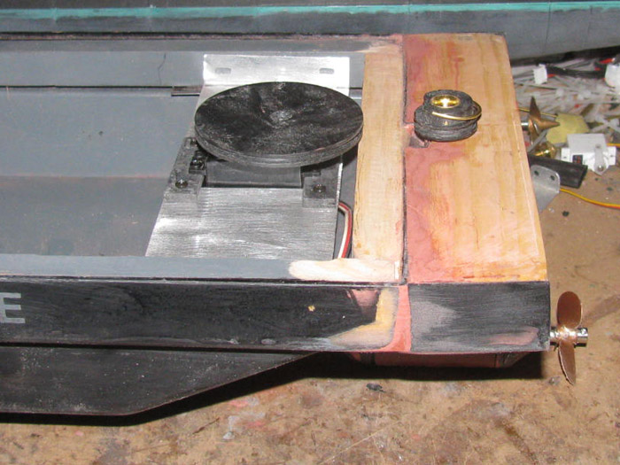
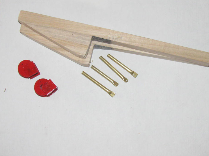
Beings I was working on the stern, I measured for the pod location and
how deep it will extend down in to the water.
I want a rudder spacer above the pod to help with turning when the motor
is not running.
I did this mostly to get more surface to glue the pod pvc connector
to the rudder turning tube.
1/16" is not enough to hold for very long.
The rudder piece has been ground to fit the connector.
The gray part is also PVC so the glue will bond the connector to the
rudder.
The brass rudder shaft goes in to the connector to hold it in place
and centered.
I cut the shaft hole in to the connector where the motor wires with
come up to the hull through the shaft.
I put the pod parts together on the shaft with the rudder for a look.
For size, the shaft is 1/2" and the PVC rudder is 3/4" thick at the
shaft.
I cut and ground the rudder out of 5" diameter solid PVC rod.
This is the stuff I turn end caps out of and this part was made from
a rejected end cap.
I may shorten the rudder but I am waiting for the propeller to arrive
before I do any finishing on the pod.
I may make the back like the front.
For size reference, the rudder is 2" tall, 2.125" long by 3/4" thick
at the shaft.
More info. I cut the rudder in my metal band saw
Then I shaped the rudder using a belt sander turned up side down (belt
up) in my outside big vise.
November 23rd =================================================
The bollards where cleaned up again this morning.
The glue had cured.
Bollards are now painted flat black.
Worked on the stern extension piece.
Had to make a little change to it.
The block of wood for the extension was cut with squared sides.
When I dry fitted it to the hull, it turns out the hull has a slight
angle to it.
Made the beveled cut and all is good now.
I sanded the deck again and primed both sides.
Used Red oxide.
After letting the prime dry for an hour, I taped off the top to give
the deck a 5/16" wide red stripe around the edge of the deck.
I also taped of 8 spots where the bollards will be mounted.
I got the first coat of gray on the deck.
Now I think I will go back out to the shop and sand the gray and get
a second coat on it.
I was in town earlier and at the post office was a package with parts
and propellers for the barge.
While I type this, I was thinking I should order batteries for the
barge and the Tx it will use.
With the propeller(s) in hand, I can finish the motor pod.
I am sure I will need to go to the hardware store tomorrow.
I better make a list of the stainless bolts and screws needed for the
pod and deck mounting.
I also need more flat black and gloss black.
I think I need some white as well.
Building submarines does not require white so there is none in my paint
locker. ( a little Testor bottle maybe)
I hope to get some photos while out in the shop this afternoon.
---------------------
Now this afternoon.
I was in town and stopped at the post office.
Parts I had ordered arrived.
The propeller(s) are here.
I sanded and got the second coat of gray on the deck.
Cleaned up the propeller flashing.
It is a plastic propeller.
There is no set screw.
There is a slot on the front of the hub for a pin through the shaft.
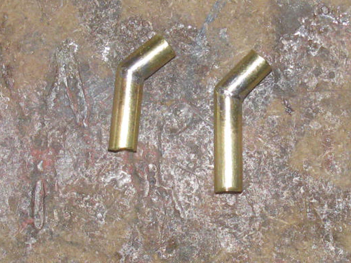
I am not going to try drilling a 1/8" stainless steel shaft.
My fix for this was to take a 1/8" wheel collar and remove material
on each side down about 3/32" leaving two square bumps.
I files on these until they fit in to the notch in the propeller hub.
I also filed on the hub notches a little to square the notch and widen
it.
Finally it all fit together.
The propeller fits on the 1/8" shaft very tight.
I had to tap on the shaft to drive it through.
A second wheel collar is used on the back to hold the propeller tight
between the two collars.
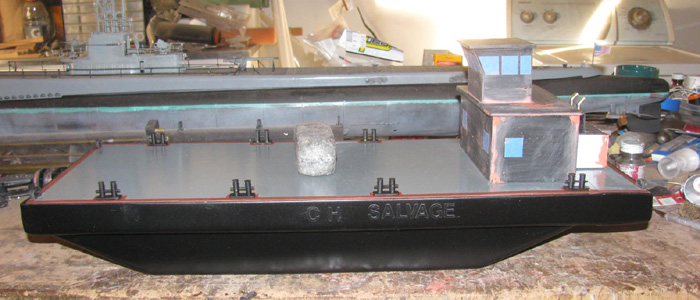
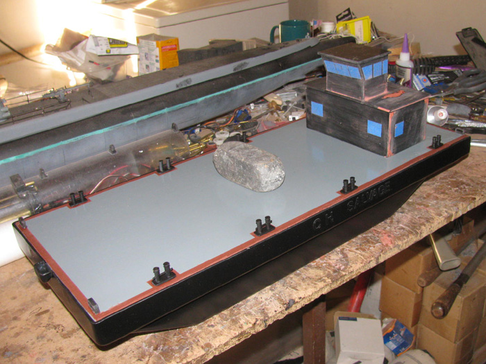
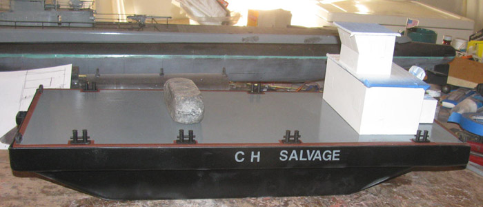
Here is a photo of the deck in place, the bollards sitting in place
and the motor pod on the deck.
I have to make the propeller shroud and mount it to the pod.
I have other items to make to put on the deck to dress it up a little.
A deck house.
Some sort of crane or boom. (maybe 2, one on each side)
Maybe some coiled rope here and there.
Couple of pusher stands on the bow.
Don't know until I start making these parts.
I think next will be making the electronics tray for the Rx, ESC, Rudder
Servo.
Wait, it that all there is?
This will help me figure out what the deck house looks like.
I plan to bring the rudder shaft up through the deck and put a pulley
above the deck.
Same with the Servo pulley.
With pulleys of different sizes, I should be able to turn the motor
pod to turn just past 180 degrees.
November 24th =================================================
I made it to the hardware store this morning.
I think I got all the stainless screws and bolts needed to mount the
deck frame, the deck and the pod shroud.
And I got the pvc connector to make the shroud.
With the Dremel and a 1/2" drum sander, I opened up the inside on one
end for the propeller.
Then I turned the connector on the drill press by putting electrical
tape on the chuck until the connector slipped on with a lot of effort.
I turned the connector outside down with an Exacto knife and files.
Then sand paper to get the outside taper.
Measured and drilled all the holes in the hull for the deck frame screws.
Still working on the stern extension.
Currently glazes and will be sanded tomorrow.
The holes have been drilled in the frame and stern extension so I should
be able to sand it, glue it and install the 2 screws.
The deck frame pieces have been drilled, glues and screws installed
on to the hull.
I did not get to the aluminum stuff for the electronics tray.
Looking at this photo, I have to go out to the shop and remove the deck.
If the glue expands up, it will glue the deck in place and I do not
want that to happen.
I want the deck to be removable. (maybe some of the deck will be glued
in place, later)
November 25th =================================================
In the shop, I worked on the stern extension.
Yesterday, I glazed the stern extension.
Today, I sanded it down, ready for paint.
Then I installed the rudder post through tube.
There will be more sanding around the post.
I drew out the disks needed to make the servo turn 60 degrees and the
rudder 180 degrees plus.
I cut some plastic sheet pieces and started working on the two pulleys
needed.
Rudder is about 1" and the servo is about 3.25".
I can modify either one to get what I need once the electronics tray
is installed.
I sanded the inside and out of the hull.
This hull is clear polycarbonate or something.
I though about leaving some of the bottom unpainted for a camera.
Thought some more and decide I wouldn't do that.
So, I sanded it all and painted the inside light gray.
Painted the top 1" of the outside light gray.
The outside will be gloss black when I am done.
My plan is to put 1/2" vinyl letters on the 1" sides to cover the gray.
Then paint the black and then remove the vinyl stickers to show the
gray through the black.
Before I can do that, I had to glaze over the 8 stainless screws that
went through the hull sides in to the wooden frame pieces.
3 on each sided and 2 on the front. (in photo, bow is to the left)
I cut the aluminum sheet for the electronics tray.
I sanded off the sign paint on one side and the factory coating on
the other.
I cut the hole for the servo to mount in.
I will be making the servo mount so I can adjust tension on the cable
between the 2 pulleys.
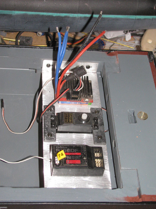
Dug out the servo, Rx and ESC to see how I might arrange them on the
electronics tray.
The black lines on each side are the bend lines to fit inside the frames
and to screw through in to the wood frame.
November 26th =================================================
Finished the 2 pulleys for the rudder control.
Made 4 closed chocks.
Painted the chocks, bollards and sides of hull after sanding the second
coat of glazing.
That is all I did in the shop.
Now in the house, I had a total computer failure.
I am currently completely rebuilding my software list.
I have all my site passwords on a flash drive.
In fact I keep all my data on external drives.
Nothing on my computer hard drive.
I am slowly reloading software I use the most.
Started with Firefox.
Only problem is I do not like the new Firefox version which is a cloud
based thing.
But it gets me to the forums.
But I could not sign in.
No passwords.
They are on a flash drive and it requires Excel to open.
So I had to look for the box.
Got it.
Loaded Office and I am good to go.
Got passwords.
Now to go to the site and login.
I still have not found where to turn Windows 7 to emulate XP.
Anyway, I have a lot to do to get back to where I was.
And yes, I back up everything at least in 2 different places.
But to get it all organized.
1 step at a time and I will get most of it.
November 27th =================================================
Worked on the 2 pulleys.
I returned the disks to make them round.
When gluing the parts together, the disks slid a little and needed
turning up.
I made another disk to go on top of the rudder post pulley so I would
have enough to drill and pin the pulley to the rudder post and allow the
3 wires to come up through the post from the motor pod.
Drilled the rudder post pulley out to just less than 1/2" to a tight
fit over the post.
The large pulley will get 2 or 4 small bolts through the pulley in to
a circle servo horn.
It too was returned to true it up.
Lettering was applied to the sides of the hull and was painted gloss
black.
This may need to be redone as it was very cold outside and the paint
did not dry with a good look.
Will see tomorrow.
November 28th =================================================
In the shop, I thought I would work on the rudder steering system.
I cut 2 rings of 1/16" to use as bearings in the rudder post.
The top end will have the small pulley riding on it to hold the rudder
post up.
The bottom ring is so the rudder can not be brought up to where it
touches the hull bottom.
The large pulley will be mounted on a circle servo horn.
The circle horn has been mounted to the large pulley.
Here I was measuring the rudder post with all the parts on the post.
Currently the rudder post is in the small vise with the motor pod main
body and the extension rudder in place with epoxy.
Glue has been applied to the stern extension, put in place and 2 screws
from the inside of the hull through the stern support block and hull side
in to the extension block.
Note on the extension block.
It is 2 pieces of pine, glued together with the grain opposite so it
will not warp.
The bottom is 1/16" short of the hull measurement.
I added a door skin sheet.
Same material as the deck.
Before I glued the door skin on the bottom of the extension, I drill
a lot of holes in the extension stopping short by 1/4" of going through.
I left 3/4" on both sides of the rudder post hole for the 2 screws
that holds the extension in place.
The glue will take over after it cures but the screws are there.
On the bottom of the extension the door skin extends 1/2" under the
hull and glues to the hull step.
The rudder pulley will sit on top of the extension deck.
The servo pulley will be up above the deck as well to line up.
There is some filling after the glue cures to make the extension flush
with the hull.
Fill the gaps.
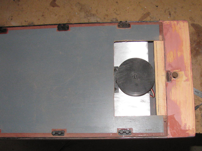
With the hull off the work bench, I decided to start mounting the deck
details.
All 8 bollards are glued in place.
The 4 close chocks are glued in place.
I have been thinking on what to build on to the front.
Pusher bars?
Pusher bars with some sort of over hang with drop able weighted lines
to hold the boats against the push bars?
Something that extends from the bottom of the push bars to go under
the rescued boats.
All too complicated.
Requiring more servos than I have channels for.
Yesterday an idea came to me.
Not giving it away just yet.
Going to build a mock up and see if it will work.
Requires just 1 servo.
I happen to have 1 very high torque servo sitting on the bench I did
not use in the Gato.
Got to build a mock up so I can see if the servo will push or pull to
make thing happen.
Also, all the other ideas require different size attachments for different
size boats.
This new idea does not care what size the boat is, up to a point.
November 29th =================================================
Today, I fitted the rudder post in to the stern rudder through tube.
The glue I use to install the rudder through tube, expands.
It apparently expands enough to change the shape of the 1/2" brass
tube.
I had to use a Dremel 1/4" sanding drum and a couple of files.
Round and half round to get the tube back to round.
Polished it and the rudder post, several times until the rudder turned
easily.
Cleaned up the 2 spacer brass rings that go between the hull and the
rudder and between the hull and pulley.
Drilled the pulley and rudder post for a through pin of 1/16" rod.
Also drilled the pulley for the cables but it is on the front side.
Sat down on my milk crate and with Exacto knife, I removed the vinyl
letters.
I am actually surprised how well they came out.
The vinyl letters are 1/2" tall.
I have removed the rudder and I am preparing the stern block for priming
and painting.
There is some glazing to do.
I have jury duty tomorrow, so I plan to put the glazing on today and
let it dry until I get done with jury duty.
November 30th =================================================
Last night I got the message that I was not needed for jury duty.
So out to the shop I went this morning.
A bit cold but it is warming up.
I sanded the glazed parts of the hull. (stern block)
Sanded the rudder where it needed a little glaze.
Applied glaze in the spots not yet filled. (maybe 2 more times)
Cut up plastic sheet to make 2 spacers for the rudder servo.
It needs to be raised up so the 2 pulleys line up.
I need to get 8 small bolts for the servo and the spacers.
Going out to measure so while in town later today, I can get the bolts.
Maybe 4 screws and 4 bolts.
Done for now but I will be out in the shop later today.
-------------------------------------------
Now later in the day.
Working on the electronics tray.
Got the bolts while in town.
Turns out, I will be using screws.
Originally I was going have slots on the servo mount to apply tension
on the steering cable.
But I could not figure out how to get under the pulley to tighten the
bolts.
While fitting the tray in to the hull, it became obvious that if I
slots in the end of the tray, I could move the whole tray and tighten the
screws for tension.
So there are slots in the end of the tray.
The screws will go in to the deck frame that is screwed and glued in
to the hull.
Servo mounted on tray.
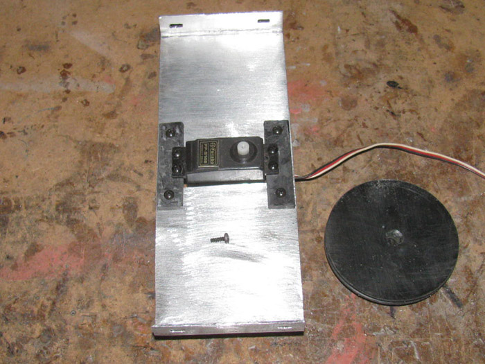
Pulley mounted on to servo.
The electronics tray set in place in the hull.
The servo pulley and rudder post pulley line up.
There is a plastic piece mounted to the bottom of the wooden frame
that the tray sits on.
I set the Rx and ESC in place for fit.
I think this is the easiest install I have done.
December 1st =================================================
I was not sure what I was going to do in the shop today.
I went out there any way.
Sitting on the bench is the hull with the red glaze.
So I will start sanding the glaze.
Got that done and looked it over.
Looks like it might be done.
If not, a very light layer on one end will do.
Before doing that, I needed to glue shims on each end of the stern block.
In the above photo, I can see the small step on the wooden block on
the side.
The block ended up a little narrow, so I will build it up with a couple
of 1/16" plastic shims I can sand down as needed.
While the glue cures, I will do some thing else. ? ?
With the pulleys sitting in place, I can measure for a deck house.
My original thought was to make a deck house that lifts up to get access
to the electronics.
This requires building a deck house and a frame to fit through the
deck standing proud about 3/8" to 1/2" to stop water from running in to
the hull.
But the more I think about it, the less I like the removable deck house.
Consider this.
I only need to get to an ON/OFF switch to run the boat.
If there is an maintenance needed, I can remove the deck completely.
So, I might glue as well glue the deck house direct to the deck eliminating
the splash frame.
I have a plan and I have decided on a size for the deck house.
Out to the tool shed and cut some door skin to size.
Back to the shop and start gluing the deck house walls together.
This is a small job so I decided to try using epoxy to glue the deck
house together.
I do not use epoxy so I do not know how it will react to my parts.
I was going to make the deck house out of sheet plastic.
But the plastic I have is getting old and it has become brittle.
It doesn't bend but cracks.
----------------------
I now have a deck house made of wood door skin.
I also made a much smaller deck house to cover the rudder pulley.
I will make it look like an engine cover.
Thinking of putting exhaust pipes and mufflers on it.
I painted the motor pod main section and rudder.
I have been putting it in and out of the rudder post.
Why not get the first coat of paint on it.
It looks so much better.
Like building a boat and finally getting that first primer coat on
it.
Looks almost finished.
December 2nd =================================================
So much small stuff to work on.
I will work on several different parts today.
I worked on the deck house.
I had to glue 1 corner on the main deck house.
I sanded all the corners to flatten the over extended wood panels.
I started on the hull.
I sanded the glazing and the 2 stern side spacers.
I ran in to some glaze that did not harden at all.
I ended up digging it out the best I could and filled the void with
epoxy, hoping to get a solid finished stern extension.
Moved on to assembling the motor pod.
I cut the recess for the cup seal.
Drilled 3 holes in the front and 3 holes in the back of the motor body.
Bolts will hold the front and back of the pod on.
The back part is made up of 2 pieces made from plastic.
The back part has a recess cut in to it for the shaft seal.
There are 3 bolts inside the pod to join the 2 back parts.
I got all the hole drilled and tapped.
I used the bolts for tapping.
The holes I drilled for the bolt to thread in to is 1/16".
I have to assemble the parts to the pod to make sure the propeller shaft
is straight and turns freely.
I can not do that until the epoxy in a hole I drilled in the wrong
place, cures.
Looked through my supply of paint, I can can not believe I do not have
white.
But, I build submarines and there is no white on any of them.
There is more to do, I just don't know what I will work on until I look
over what is non the bench.
I know this barge will be followed by the Gato.
There are a lot of loose parts on the bench that need to be assembled.
-----------------
This afternoon, I did a little more.
Here the electronics tray is set in place so I could measure the pulley
location.
The rudder post pulley is also installed.
I made a 1/16" brass rod clip to hold the pulley on the rudder post.
The motor pod can be seen.
The nose and back have been fitted along with drilling the holes for
the bolts.
Stuck the propeller on it's shaft in to see the look.
The shroud is not attached.
Looking down in to the hull at the pulleys.
This was needed to measure for the deck house.
Set the deck on to check level from main deck to stern extension.
The electronics tray is adjustable by 1/4" to tension the pulley cables.
The deck will be cut to to the deck house inside measurements.
The deck will lift off without touching the servo pulley.
I can see the 2 back closed cleats will need to be moved.
The deck house will hit them and the closed cleats should be at the
stern edge of the hull.
Not a problem.
The Exacto knife popped them right off.
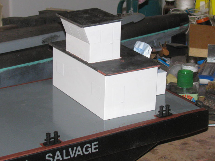
The deck house and engine cover in the process of being built, looks
good sitting on the deck.
I do think I may add a small wheel house on top the main deck house.
The engine house needed to be turned 90 degrees. (Not done in this photo)
Cut 1 a side off and moved it to the short side.
The roof is not glued in place.
I can remove it to see where to draw the lines to cut the deck so the
house sits on the deck and the deck comes all the way to the inside walls.
December 3rd =================================================
I was gone most of the day.
Got a few minutes in the shop.
Sanded the stern glaze from yesterday.
Too cold in the shop at night so I will be bringing the hull inside
tonight to cure.
After sanding, I used a straight edge to check my work.
Never a good thing.
I can see the lower spots needing more glaze.
Both side where I put the shim to bring the wood out to thehull sides
and the top of the stern block at the joint between the wooden block and
the hull edge.
Got a long piece of sheet plastic.
Checked it straight on a piece of sand paper.
Spread the glaze from the hull edge to the middle of the wooden block.
It is not much but the deck was not flat.
Now that I type this, I think I need to check the hull to wooden block
to see if I need to glaze that so there is no line.
Or I might paint the stern from the hull to the back edge primer red
as part of the safety edge of the barge.
I will know better tomorrow after I sand today's glazing.
This morning, before leaving I was in the shop to start making a bigger
engine cover.
Mostly taller for the 3 wires to the motor down the rudder post.
I made the parts wider to see if it looked better when taller.
I think I added a 1/2" in width.
Don't remember.
I just cut plastic parts and glue then to double the thickness.
While out and about, I stopped by the hobby shop to get a 1/8" stainless
rod which I hope will work for my bow sub catcher idea.
I still have not ordered batteries.
I put a note here next to the keyboard to check on that in the morning.
I will also look for the silicone high temp motor wire I have some where
in a parts box.
If I wire the motor I can close up the motor pod and paint it.
Got to find some flat black hull paint.
The gloss black did not have the look I wanted.
Maybe semi gloss.
Last time I looked at the hardware store they had no flat black and
1 can og gloss.
I brought that can home.
December 4th =================================================
I got the hull glaze sanded.
Still a couple of very small blimishs.
Glazed them.
Measured the location for the deck house to cover the servo pulley.
Cut the deck opening.
The pulley is above the deck.
In the photo, the servo is all the way back.
There is 1/4" to move forward for adjustment.
Between the pulleys is a gap in the deck.
The deck is removable but the cross piece has to be fixed in place
on thehull to get the deck over the pulley.
I cut a piece from the removed deck piece and it has been glued in
place.
Currently with weights holding it down while it cures.
Set the deck house in it's location.
There will be a cut in the back wall of the deck house for the steering
cables and main motor power wires to go through.
Set the engine cover on.
This cover is not the one I will be putting on the barge.
It is to low in height.
I am making a new one.
December 5th =================================================
Sanded the stern block again.
Need a little more sanding and glaze on the deck part I glued in.
One side is a little high and can be seem easily.
Sanding done and glaze applied.
The glaze on the deck house has been sanded.
I took a steel square to the deck house and it was not square by about
1/16" on one end.
To the table saw.
See the saw to cut at one end of the house but not the other.
I slowly moved the house in to the saw with each pass.
The first couple of passes did not cut the complete side.
When I could see the side being completely cut, I stopped and set the
square in place to check.
The house is square all the way around now.
Back in to the shop.
Yesterday, I made a new engine cover.
This one is in plastic.
I sanded the sides and back to true up the corners.
Then the top.
Set the engine cover against the deck house and marked the inside edge
lines.
This is where I will cut the deck house for the steering cables and
motor wires.
Made the cut and filed it to finish.
Drilled some dimples down the edges where the engine cover will be glues
to the deck hose.
I wanted more grip for the glue.
Got what I wanted and applied epoxy to the 3 edges and clamped the two
parts together.
Trying to decide if I want a wheel house on top of the deck house.
This would mean making railings on top of the deck house.
A couple of ladders as well.
I am thinking this could be done later
As soon as the deck house/engine cover have cured, I can start on the
pieces that go in the deck to hold the deck house on.
On sailboats it is called the hatch lip.
A 3/8" tall piece to keep water from running in to the hatch opening.
The deck house drops down over it and it held in place by some sort
of mechanical devise.
I the past I used rubber bands and springs.
Today I see magnets being used.
I though I might make a couple of fire extinguishers and through pins.
Not there yet.
-------------------
Back out to the shop.
Sanded the glaze on the stern extension.
With steel square in hand, I checked the stern extension to the hull.
The stern block is higher at the back of the block than at the front
where it meets the hull.
This causes the deck house to not sit level on the deck.
The deck house is on the main deck but the engine cover is on the stern
block and holds the deck house back up off the deck.
I put the belt sander in my outside big vise.
I spent 15 to 20 minutes sanding down the stern block a little at a
time.
Checking it with the square after every 2 or 3 passes on the sander.
Also had the deck house out there to use for checking.
I think I got it.
I did sand a little to much off the right side.
The fix it to glaze it using a long straight edge to apply the glaze.
More sanding to come, tomorrow.
The far side is where I had to raise the stern block up to meet the
deck panel.
The near side was to fill a small gap between the stern block and the
hull.
(probably would not have been noticed after paint)
I hope I am where I can do a little sanding cleanup and then start
priming the hull bare wood parts.
The deck house need more work.
The roof is not fixed in place and there are details that need to be
glued on after I make them.
December 6th =================================================
Sanded the stern hull extension.
Bad news.
I made a small change to the extension and there is more glazing and
sanding in my future.
The change was caused by the engine cover.
It can be fixed.
I have not decided whether to attach the deck house to the deck or make
it removable.
I have to do some measuring to determine the size of a transportation
box.
Thought, I did think of just making a stand and carrying the boat without
a transportation box.
But, one of the reasons for the transportation box is to protect the
boats here at home from damage while being stored.
Cut sheet plastic to make a new roof.
It looks funny to me with no overhang.
So the new roof will have overhang.
It is 2 layers thick so there was bonding involved.
It is currently clamped to the work bench to make a pressure bond.
I made 2 engine exhaust pipes and cut plastic to make 2 heat shields
to go on top of the engine cover.
That big box behind the deck house looks so bare.
Here are the 2 exhaust pipes.
Diameter of tubing is 1 size smaller than 1/4".
Continuing today.
Shaped the heat shields.
Drilled for the exhaust pipe.
Glues the exhaust pipe in the heat shield.
Glued the 2 exhaust systems to the engine cover.
Second view.
December 7th =================================================
It is a bit cold outside.
I am getting ready to go in to town.
But I was putting a couple of wrenches back in the shop so I did a
little sanding.
It wasn't much but the wooden stern extension glazing is done.
If it warms up, maybe this afternoon I can get a primer coat on the
wood.
I figure 3 or 4 coats to cover and seal for paint will do.
I got a list of items needed while in town.
3 hard wood 1/2"x1/2"x3' strips.
Flat black paint.
Some stainless steel bolts and nuts.
I hope to get more done and report later today.
-----------------------
Yep, it's later in the day.
I turned on the heater in the shop.
Got it up to 65F so I was able to get 2 coats of primer on the wooden
stern block and 1 coat on the hull side where the lettering goes.
Tomorrow I may not be around to work on the barge.
More VA appointments.
All is good but work on the barge is about to slow down a little. (I
am guessing until I see the doctors tomorrow)
December 8th =================================================
Ready to go early.
15 or so minutes in the shop.
Sanded yesterday's primer coats on the hull.
Sprayed another coat on the hull.
Taking care so if this is the last coat needed, I do not have to clean
it up.
Sanded the deck house.
Looks good.
Will start painting the deck house.
Taped off the engine cover roof. (different color and is plastic. No
need for primer coat)
Got a light tack coat on the deck house.
Just trying to seal the wood grain.
Just enough time to type a few words here.
Off I go.
December 9th =================================================
Yesterday, I did some touch up gray painting.
Today, I found out that the paint I used yesterday doe not match the
paint I used originally.
So today, I removed all the parts from the deck 8 bollards and 2 closed
cleats.
Sand the deck down with a palm sander and repainted the deck.
The back 2" of the deck was repainted yesterday but today I ended up
repainting it all.
After it dries completely, I will need to put the red detail line back
on the deck.
That line needs to continue back on to the stern extension.
I will tape it all off to paint it all at once.
Painted a second coat of white on the deck house.
It's going to take more.
After painting, I cut plastic sheet and I am building the wheel house
that goes on top of the deck house.
Got 3 sides on the bench with square blocks holding it in place while
the glue cures.
The front will go on last.
It is scored and bent forward for the top half to look like the windows
that lean forward.
Tonight, I will apply the letters to the sides of the hull, again.
After that, I will if I feel up to it, tape off the deck and stern
block for the red lines.
After removing the bollards and close cleats, I cleaned off the glue
from the bottom of all of them.
They are ready to be reinstalled once the painting of the deck is completed.
Batteries should be here Friday or Monday.
Then I can start on wiring the motor pod.
December 10th =================================================
Letters were applied.
Using masking tape, I taped the deck edge lines and bollard stations.
Masked off the hull stern block to match the deck. ( hope)
I got 2 coats of the red primer on both the hull and deck.
Later in the day, I looked at the parts and I see problems.
The new paint cracked over the gray.
I think I have said I do not like painting.
I lightly sanded and I used a stainless brush to get down in the bottom
of the cracks.
I have painted a third coat or red primer.
I will let that sit over night.
While in the shop, I thought I would trim the excess plastic sheet off
the front wall of the wheel house.
That was so exciting.
I was about half way through removing/trimming the plastic sheeting,
when the wheel house decided to explode in to 4 individual parts.
Well now.
That should not have happened.
Okay.
I setup my wooden blocks to keep the house walls straight and square.
I re applied bonding cement.
Put it all together again.
I will let this sit over night.
Before I continue the trimming, I think I will run a line of CA down
each corner on the inside of the wheel house.
-----------------------------
Came in the house and there were 2 messages that the package (batteries)
is sitting at the post office.
Problem, I was there this morning.
Called and talked to someone at the post office.
They went and looked in my PO box.
They said there was a package in my box.
Great. I will go again tomorrow and pickup.
The problem with living in the desert, I have a PO box and the county
gave me a street address.
That is a box out on the highway.
Problem is the street name.
There are 2 street with names that are close to being the same.
Cabrillo St and Camarillo St.
My stuff has been delivered to the other box several times over the
years.
I usually get my stuff about a month later.
The other address is for a house that burnt down over 10 years ago.
--------------------------
I was in the big town a couple of days ago.
I stopped at Lowes and got some 1/2"x1/2" poplar wood strips.
To use under the deck for stiffing and to make the 2 push bars at the
front of the hull.
I put another coat of white on the deck house.
I am not liking the way it looks.
The wood gain is swelling and becoming a visual problem.
Tomorrow I think I will have time in the shop to assess the problem
and maybe cut some plastic sheet and build a new deck house.
Reason for thinking this way.
On the back of the deck house is mounted the engine cover which is
plastic.
The paint on it looks really good.
Nice an smooth.
Cutting plastic panels to build the deck house will take about 10 minutes.
Gluing will not take much longer because I have wooden block to hold
it together. . . after the wheel house is done.
December 11th =================================================
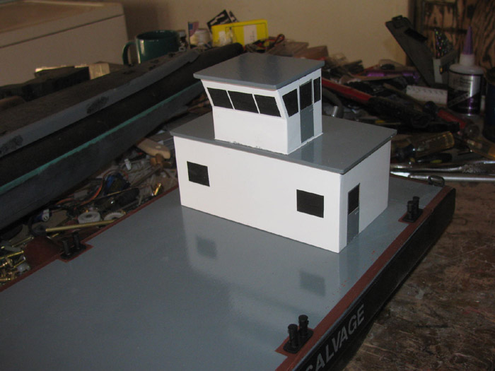
This morning, I cut plastic sheet to make the walls of the new deck
house.
Each wall is made of 2 layers of 1/16" sheet plastic.
Clamped the 4 walls in the vise to cure under pressure.
Went to town and picked up batteries from post office.
Two 1500 mah Rx and two 1800 mah boat batteries.
Back in the shop.
Removed the deck house walls from the vise and started sanding the
edges down to size.
Using a steel square to make sure I get the corners all 90 degrees.
Started gluing a side wall to the front wall then a side wall to the
back wall.
Tomorrow, I will join the two assemblies to make the deck house.
Finished making the wheel house which will go on top of the deck house.
It is a small wheel house so it is only 1 layer of plastic sheet for
the walls.
I did put a couple of plastic pieces inside to stiffen it up some.
Deck and hull stern painting.
I still have a paint problem.
The red primers spider veins on the gray paint.
I sanded the stripes down and then I washed with paint thinner.
Let dry. ( I worked on the deck house)
I turned on the heater in the shop and got it up to 70F in hopes that
the paint will dry quicker.
I looked at it all before leaving the shop.
It looks okay.
(I was thinking if it spider cracks showup again, I might try some
rusting of the barge edge to cover it up)
Planning for tomorrow.
Lots to do.
December 12th =================================================
In the shop, late.
It is so windy, there will be no painting today.
Before going in to the shop, I had to chase down a couple of metal
trash cans that have been trying to escape.
They just haven't learned how to jump the 4' fence, yet.
Looking at the deck paint, I think I will leave it as it is.
The paint on the stern block, not so good.
Sanded it down and wire brushed it, again.
Got a quick coat of red primer on it without going outside.
So it is back to all the plastic parts I have been making for the deck
house and wheel house.
Wheel house is top center.
The deck house is all the other parts.
Yesterday, I got the engine cover mounted to the back deck house wall.
I cut the engine cover free from the original wooden deck house.
Sanded the edge clean.
Glued the back wall of the deck house to the walls.
Set the roof and wheel house on for a look.
Front.
Side.
Back.
It is coming together.
Cut 2 plastic pieces to make the roof of the wheel house.
Sanded to size and glued them together.
Currently in the vise to cure.
Looked for 1/16" brass rod for the hand rails.
Yea, I do not have enough.
Will pick some up next week when I am down in the big city.
The rail will be on the top of the deck house.
Need to think about 2 ladders and how to make doors and windows without
cutting them in.
Maybe tape them out when I paint the white and leave them black.
Brush some streaks of light blue on the black to look like sky.
Not sure about the doors.
Need 4 to look right. 2 in wheel house and 2 in deck house.
I will look for some thin plastic, like used for packaging.
Glue it on and leave the raised look.
As soon as I get the paint on the stern block to look right, I will
paint the hull black again.
Once the black is done, I can start work on the wiring of the pod through
the rudder post.
Things to do but compared to submarines, this is going very fast.
Monday will ne 30 days working on it. Off and On.
December 13th =================================================
No wind today.
Painting will be something I try to do today.
Masked off the top of the hull so that I can paint just the 1/8" rail
all the way around the hull without getting paint on the inside of the
hull.
Got 2 coats on the rail.
Let it dry about 45 minutes to an hour between coats.
Got that done.
Turned the hull over to paint the outside.
1st coat was very light tack coat.
2nd coat was another light coat that just barely covered.
3rd coat was a little heavier to get a good solid coat.
Waited an hour and an half for the 4th coat.
Good a good coverage coat on the complete outside hull.
Let dry about 45 minutes before bring the hull inside.
Still no wind.
Between coats on the hull, I worked on the deck, the deck house and
the wheel house.
The deck got it's bollards and close cleat back.
The deck house and wheel house got sanding and more glazing done.
I still have some small spots I am working on.
The vinyl letters are still on the sides of the hull.
I will pull them off in a day or two.
The blue tape on the deck house and wheel house at the windows and windows
in the doors.
The doors will be outlined scribed after the painting is done.
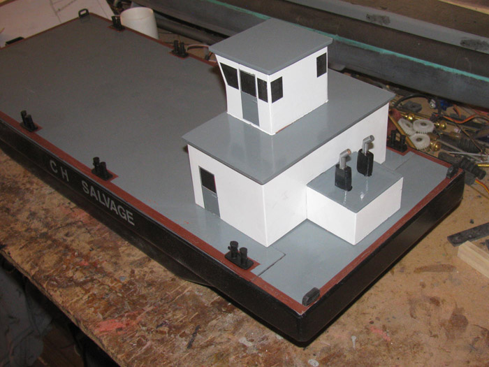
I set the deck house and wheel house on the deck which is on the hull.
Here are 3 photos.
December 14th =================================================
I did not get much time in the shop.
I got 15 minutes this morning and 30 minutes this afternoon.at the
most.
I sanded the glaze on the deck house and wheel house.
I had been thinking on how to make door details.
I looked last night for my 1/64" wide tape to do an outline of the
door frame that I woud paint over.
I did not find the tape.
When I got out to the shop, the first thing I did was fire up the heater.
It was 45 F in the shop at 2pm.
While doing that, I looked down at a test board.
On it are various test I have done to check if something looked good
or the glue would hold two different materials together.
An on one edge there was the weld line test I did to reconstruct the
weld lines on the Gato hull.
I used 2 pieces of tape with a gap between for the weld line that I
had glazed over.
Then sanded down to the tape and removed the tape leaving a nice weld
line.
Thought. . . . Why wouldn't that work to make doors and frames?
So I taped off the door locations and glazed them this morning.
I sanded and pulled tape this afternoon.
The doors are raised slightly.
The windows are still taped until I paint the white.
Photo . . Roof being clamped after gluing.
December 15th =================================================
Almost didn't make it in to the shop.
I stopped what I was doing and got 1 hour the shop.
I cleaned up the deck house glazing and the wheel house glazing.
I made 4 door handles for the doors.
Quick and dirty.
I cut 3/16" long brass wire.I am not sure what the diameter is.
30 thousands? ? ?
It is what I used for the lower rail on the Gato. (left overs)
Taped off the roofs of the Deck house, wheel house and engine cover.
They will be light gray like the main deck.
It is a bit cold in the shop but the heater is on which helps a lot.
A quick pass of white to tack the paint.
Each piece was held above the heater about 3' to help it set.
While I let the painted parts sit, I removed the vinyl letters on the
hull.
Again, I am amazed I got clean letter lines.
I also mounted the 2 stern closed cleats on the stern block.
Tomorrow I will paint the white again if it needs it.
And I will install the electronics tray in to the hull.
Then I can make up the steering cables.
Still need to make the pusher bars for the bow.
December 16th =================================================
Looked over the deck house and wheel house.
There were some small runs.
Sanded out the runs and repainted.
Removed the roof tape.
Window and door tape still in place.
The roofs will be painted light gray like the main deck.
Installed the electronics tray.
I think I need to find another Rx with 6 channels.
This Rx is out of another boat and will want it back.
I have a 4 channel but I need a 5th channel to use with a knob control.
A stick will not do.
The rudder post bushing has been cleaned removing the over spray paint.
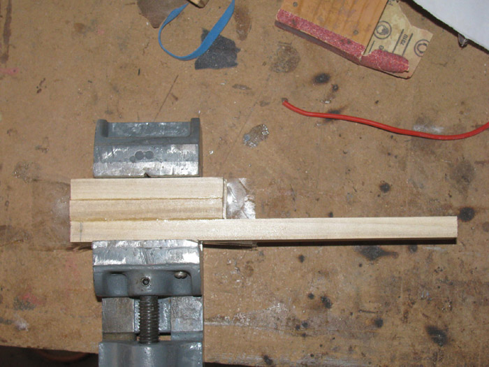
Started the 2 push bars for the bow.
1/2" square popular.
The long piece is 9".
Currently in vise until the glue cures.
Almost forgot.
Finished the motor pod tail cone and spacer.
I had to deepen the cup seal recess about 1/16". Maybe a little less.
I had to drill a recess in the front of the spacer for the shaft connector
to fit in to.
Installed the cup seal and put the 3 bolts in that hold the tail cone
and spacer together.
Problem.
The propeller shaft would not turn without a lot of effort.
Took it apart and removed the cup seal.
Reassembled and using the propeller shaft, I found that the tail cone
bushing and the spacer bushing are not straight enough.
The shaft goes through but binds the shaft.
Ran a 1/8" drill through the unit.
Cleaning up the two bushings.
Disassembled and reassembled several times.
Even used a 1/8" round jeweler's file to remove burs.
Finally, the shaft turned smoothly.
In fact I can hold the shaft and spin the tail cone/spacer unit.
Took it all apart and greased the cup seal and reassembled.
Still turns easily but with seal resistance.
I had to make another brass spacer for the rudder shaft.
Turns out, while finishing the hull stern block, I must have sanded
the post bottom and there was too much play in the rudder.
Made a longer spacer and slowly sanded it down until the keeper pin
went through the pulley and rudder post.
Tomorrow I will be down in the big city.
I will go by the large hobby shop and get wire for the main motor,
and a couple of other things.
Brass rod to make ladders is on the list.
December 17th =================================================
I the shop early.
Turned on heater and sat down on my wooden milk crate and started taping
off the doors and roofs to be painted gray.
By the time I got the taping done, the shop was up to 60F.
Time for the tack coat.
Then wait before a second coat.
Found a couple of plastic parts. (layers of plastic to make something)
Problem is, I don't remember what they are for.
Started to toss them in the track box.
Then thought, I made these for something.
The big issue is, I have parts on the work bench for 2 subs and this
barge.
As I assemble the barge parts it may come to me what they are for.
Looked at the deck house and wheel house.
Again. . . . I do not like painting.
I painted 2 roofs and 4 doors.
The doors on the wheel house look good.
The doors on the deck house are all wrinkled and raised.
Both had the same white paint on them that got painted over.
Later today when I get home, I will sand them down and try another coat.
------Now later--------
Sanding was done.
Another coat of paint on the placed needed.
Removed tape on windows where painting was not redone.
After 45 minutes, I removed the rest of the tape.
There will be some touch up after it all cures and I finish working
on the deck house and wheel house.
Railing to come.
I am sure I will mess up the paint some.
Painted the exhaust heat shields.
Painted the exposed exhaust pipes.
Going to work on the push bars I glued up yesterday.
They are ready to be shaped.
The barge is coming along and starting to look like something.
December 18th =================================================
Cut the pusher bars to shape.
Need a spacer to make the pusher bars 90 degrees to work bench top.
1/16" to 0 shim about 3/4" long on both pusher bars.
Glued them on the back of the pusher bars and clamped in the vise.
I had two things I wanted to get done today.
Well the brass ladders did not go well.
My soldering iron tip is so worn out, I could not get a pin point joint
soldered.
Worked on three steps and failed so I quit.
Have to come up with a different idea or get a new soldering iron.
Moved on to something than came up while I was trying to figure out
how to hold the deck house on to the deck without gluing.
I thought I would make a couple of small fire extinguishers on pins.
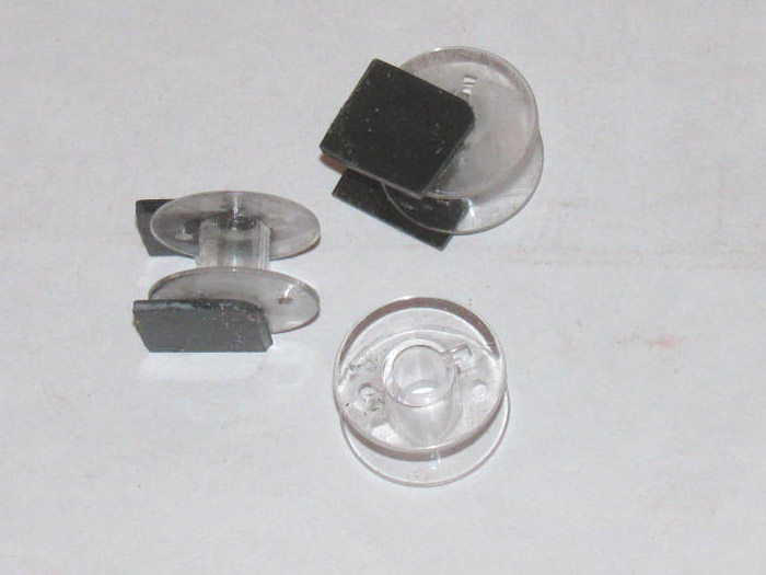
Then while at the hobby store, I saw something that would make nice
fire hose reels.
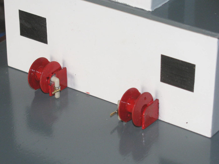
So, I thought I would make a couple for detail.
The hose reels are plastic sewing machine bobbins.
A size that looks okay on the deck against the deck house.
So, I am making 2 to see how they look when finished and painted red.
But there is a problem.
CA and plastic cement will not bond to the bobbins.
Right now I have 1 on the work bench using epoxy to see if that will
bond.
I did sand all the parts.
Day turned cold and I think it's time to go in the house.
Tomorrow will come soon enough.
December 19th =================================================
The pusher bars shims have been shaped to make the pusher bars 90 degrees
to the water.
I have been sanded the pusher bars.
Set aside.
Time to make the pieces that go in the hole in the deck under the deck
house
What are they?
Water dams?
I made a lot of these when I was building sailboats. (50/800 class
mostly)
Cut several pieces of plastic to double up the layers.
Rough cut to length.
Applied glue and they are now clamped on the work bench to cure.
Measured the deck opening to the deck house.
Needed some filing to make the opening the size of the deck house.
Got that done.
Measured and cut 3 pieces of 1/2"x1/2" popular wood to glue under the
deck to mount the plastic to.
Mixed a little 30 minute epoxy and the wooden pieces are now clamped
tothe underside of the deck.
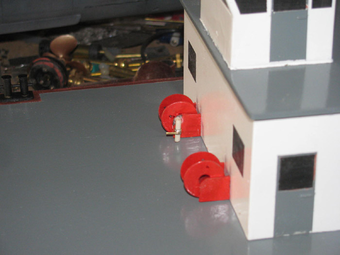
I have built 4 fire hose reels.
The two you see in the photo and two using brass rod instead of the
plastic sheet.
Once the epoxy cures, I will see which ones look best to me.
Those will get mounted to the front of the deck house.
----------------------
I thought about going to town and getting a new soldering iron.
But I have 3 appointments in town on Monday and Tuesday.
I will hold off until I go in to town for those.
Hey, it's 34 miles one way.
---------------------
Continuing.
I trimmed the water dams to the correct height and length.
I have epoxied three of the dams on the deck frame blocks under the
deck.
One goes on the stern block. (will go in later)
Clamped them so they will stay in place while the epoxy cures.
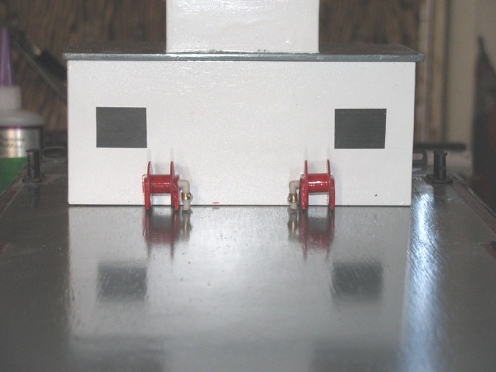
Looked over the 4 fire hose reels.
Held them up to the deck house.
The original effort seems like the one that will be installed.
Painted them red.
Original reels.
Will get a second coat, tomorrow.
I will clean up the water dams as well.
Will fit the deck house on the dams.
If I measured correctly, there should not be any clean up.
I finish sanding on the push bars.
Not sure exactly how I pan to mount them.
If I put them on by mounting through the deck, it would take about
10 minutes if I have 4 stainless screws for the job.
But my idea was to have the push bars lean back at the deck about 15
degrees or so with an arm sticking straight out at the bottom of the push
bars.
This wold make a cradle to hold the rescued boats while pushing them
to shore.
I have to check and see if my Tx channels can be reproprammed from stick
to knob.
I want a knob so the leaning will stay where I stop it and not have
to hold a stick in position because of the springs to center.
December 20th =================================================
Getting ready to put a second coat of paint on the hose reels.
Working on the push bars.
Looks good in the photo but what happened next was not pretty.
The plan here ended up with the hinge pieces needing more room in the
deck than I wanted.
I did not want to have big grooves in the deck.
So, these push bars are now in the parts box and new ones have been
cut and are glued up sitting in the vise.
Second plan is now starting.
I cleaned the paint off the front of the deck house where the 2 fire
hose reels will be mounted.
The fourth side of the deck house water dam has been fitted and is now
in place.
Clamped while epoxy cures.
-------------------------
A little more this afternoon.
Glued the wheel house on top of the deck house.
Actually the deck house roof was already mounted to the wheel house.
I Glued the deck house roof on the deck house.
Also, I installed the 2 fire hose reels.
When I bought the plastic bobbin spools, I found some fabric trim that
looks like two hoses side by side.
Going to give it a try on the spools.
It looks right to me.
It frays very easily so this may take some effort.
I was thinking a little CA on the trim where I plan to cut it might
stop the fraying.
Time will tell.
Got to make some sort of brass nozzle to mount on the wall next to the
reels.
I also need to make a supply pipe to each spool with a shut off valve.
December 21st =================================================
Not much done today.
I was in town taking care of real life stuff.
Took the push bars out of the vice and sanded all the surfaces smooth
in the belt sander.
Glued the spacer shims on and clamped back in the vise.
Cut 2 lengths of the sewing trim for the fire hose.
Soaked the ends in CA glue to keep them from fraying when I cut them
again.
Tested 1 length on the fire hose reel.
I guessed the correct length and it looks good.
Took it off the reel and will install it tomorrow.
Needed to make 2 pipes that come up from the deck to the center of the
reel.
Thought about this last night.
It soon be came obvious on how to do this.
Look through old plastic sprue parts trees for 2 90 degree corners
with nothing near the corner so I could cut out enough to make the pipes.
First tree I picked up had 4 corners just like I needed.
Cut 2 and sanded to length.
Left the down pipe long so I could fit it once the glue on the end
to reel cures.
Deck house is hanging over the side of the barge because the down pipes
are long and will be trimmed later.
December 22nd =================================================
I have sanded the push bar shims to make the push bars sit at 90 degrees
to the deck/waterline.
I will work on the installation of them later.
Back to the fire hose reels.
Let the plastic pipes I made yesterday cure over night.
(got a new soldering iron and needed to try it out)
This morning I made brass shut off valves.
Cut very short brass tubing for valve body and I ground 1/16" brass
rod to represent the valve handles.
The fire hose reels are mounted on the deck house and lift off with
the deck house.
Several photos of reels.
Not sure what I will work on next.
But once I get out in to the shop there is plenty to do.
Maybe I will try making the deck house railing now that I have a new
soldering iron.
Need to make a tensioner for the large steering pulley.
I have been thinking about that for a week.
I think I got something in mind that will work and easy to build.
2 blocks of plastic and a long stainless bolt.
I have been looking for DC stranded wire to wire the motor pod. (lots
of little wires and flexable)
This morning I used the new soldering iron and I started to toss the
old one in the trash.
I stopped because the wire I am looking for is the same as the cord
on the soldering iron.
Repurposing!
----------------------
Working on making 2 roof top spotlights.
Brass tube for housing and 1/16" brass rod for pipe stand.
Filled with CA and baking soda.
I will shape the back of the housing and lens after the CA cures completely.
The flattened rod goes in to the rood to help it bind when gluing.
I also made a domed radar antenna.
I have 1 fire hose reel with hose installed and 1 ready to be finished
off.
December 23rd =================================================
Started making the steering cable adjuster.
Gluing plastic pieces together.
In the vise, now.
Cleaned up the 2 spotlights.
One on the left has been cleaned and the one on the right is next.
Primed the spotlights.
Installed on top of the wheel house.
Will paint later when touching up everything.
Did a little with the fire hose reels.
Wrapped the hoses around the reels.
CA on the under back side to hold in place.
I left the end loose so I can make and put some sort of nozzle on them
of at least hose connectors and maybe may a nozzle and mount on deck wall.
Thought I would give my new soldering iron a go.
I made a ladder and hand railing.
It looks a bit wide but I do not think I will try to make it narrower.
I need to make a second ladder.
The upper hand railing is 1 piece of brass rod.
I think it will go all the way around and make the other ladder side.
If not, I will connect the railing at the center back.
There will be a few stanchions and a second smaller rail.
The ladder and railing is just set in place for a look.
I am thinking I will finish the ladder and railing and stop with the
details.
I looked at pusher tug masts with light but they have too much stuff
on them.
Lights, radar, Radar reflectors and antennas of all sorts.
I may add 1 or 2 whip antenna. (don't know)
December 24th =================================================
Finally got out to the shop.
Pulled my wooden milk crate over to the bench where I am working.
I build the second ladder and railing.
Measured the roof of the deck house for the locations of the stanchions.
Drilled the holes.
I cut brass rod for stanchions, one at a time.
Putting each stanchion on the deck house, I ground the stanchions to
height.
Using a small machinist ruler with sliding T.
Once I got all the stanchions cut and ground to height, I went back
and glued each stanchion if making sure it was straight
The photo is before gluing.
I have bent the left side ladder railing to fit the roof line.
Now I need to do the same to the right side ladder and railing.
It is just sitting there for the photo.
There will be a second railing made of smaller brass rod under the top
rail.
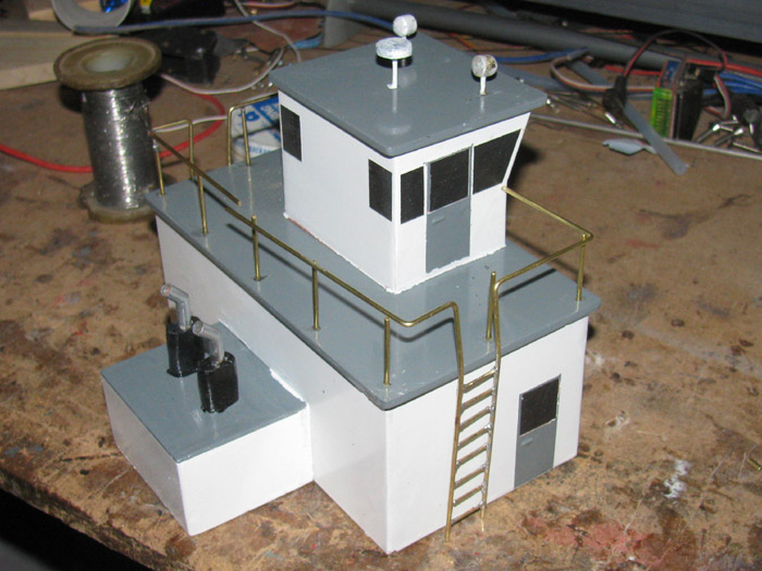
I am also fixing a small gap on the deck where it meets the stern block.
One side had a gap of about 1/8" that looked bad.
I thought about dropping a coil of rope over it but this is where the
deck comes off the hull.
So I am fixing it.
Just using glaze and paint.
December 25th =================================================
Yesterday, I prepared more railings.
This morning, I installed the second railing pieces.
Went on quick.
There is some solder clean up with a file but not much.
Once the solder is cleaned up, painting begins.
I think I will paint the railings and touch up the rest of the barge.
Still need to make fire hose fittings.
I think I am done for now with detailing.
Deck house and wheel house.
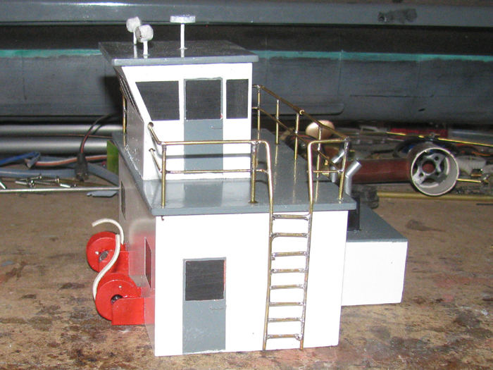
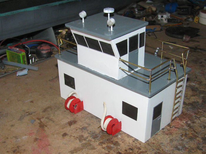
Deck house and wheel house on the deck of the barge.
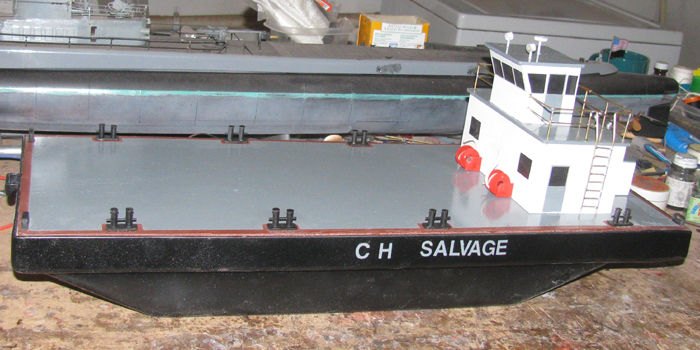
I need to make 2 plastic pieces for the bottom of the ladders that will
mount to the deck house and securely hold the ladder in place to the deck
house.
December 26th =================================================
I had about 30 to 45 minutes in the shop this morning.
Painted the spotlights black.
I did not like the white.
Worked on the glazing on the stern block.
Sanded and reglazed.
Cleaned the railing with paint thinner.
Files a couple of spots where the solder was sticking out and sharp.
Applied a first coat of gray.
It is going to need a second coat.
The brass shows through in spots.
I will let this paint dry then apply a second coat.
After that, I will move on to touching up the white.
There are some places that are just too much to be considered work
related.
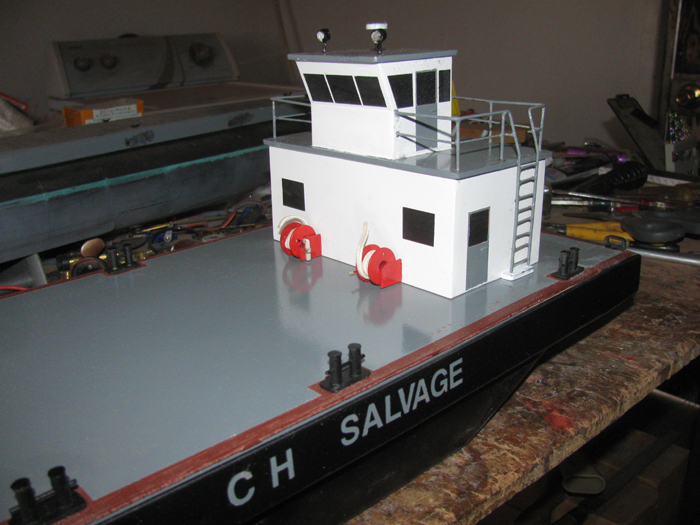
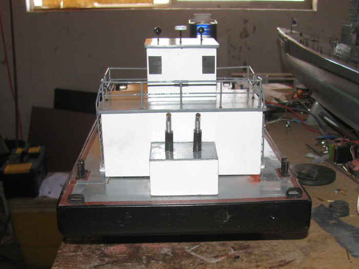
Finished up the shims on the pusher bars.
The hull sides are not 90 degrees tot he bench top.
I had put a 1/16" plastic shim on last week.
Today while fitting, it took another 1/16" to get it square.
In 1" distance I needed to go from zero to 1/8" to get square.
Go that done and sanded for primer.
Photo just before applying primer.
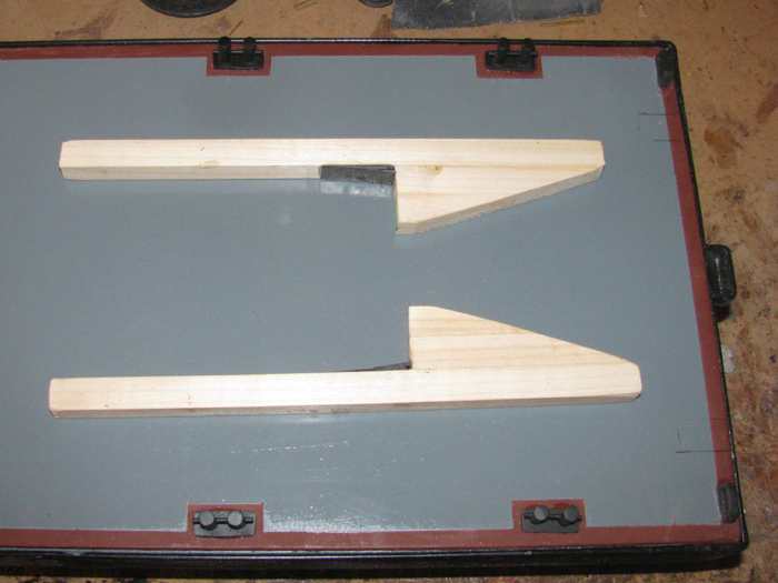
December 27th =================================================
Progress.
I did touch up on the gray railing.
After cleaning up brushes, I found some more spots.
Not to worry, I have gray touch up on the main deck to do.
I went over the deck house and wheel house using an exacto knife to
scrape some of the gray splatter off the white.
I got most of it but need to wash the parts to get all the small dust
particle off to see better.
Repaired 1 of the fire hose valves. (it as missing the handle)
Taped the pusher bars on the deck to take a look.
The pusher bars are over length.
I will cut them once I decide on how deep I want them below the water
surface.
Remember, I will be pushing submarines more than surface craft.
Example: 1/72 scale Skipjack keel is about 4" below the surfaces with
the centerline about 2.25" below the surface.
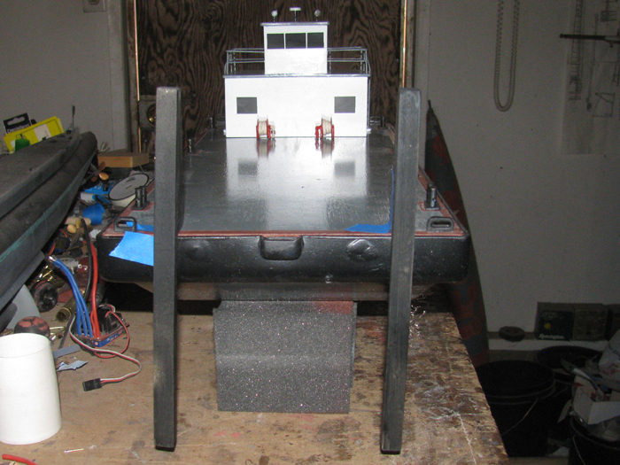
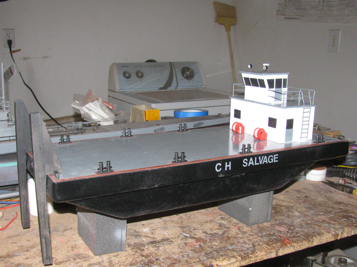
Push bars are not straight.
They are taped in place and falling over.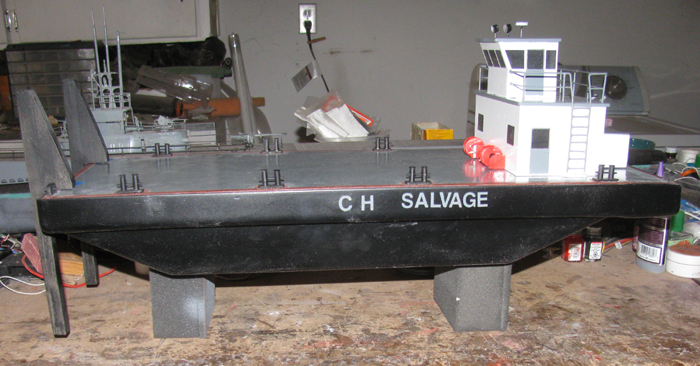
Well I can not leave well enough alone.
Looking at the photo of the barge straight on with the push bars in
place does not look right to me.
The push bars look too thin.
Out to the shop and I dug the first push bars out of the parts box.
I put two push bars side by side.
This makes them 1" wide.
This is too much.
Looked around the table saw and found a scrap piece about 5/16" wide.
Held that next to one push bar and it looks better to me.
I set the table saw to 3/8" and ran the original push bar through.
Held it up and it looked better.
I think I will go with this and ran the second push bar through the
saw.
I can always cut a little more off it it needs to be thinner.
I cut the 2 original push bars and sanded the paint of one side of the
second pair of push bars so the glue will adhere better.
Cleaned the dust off all 4 pieces and applied glue.
Put packing tape between the two units so they do not bond to each
other or the vise.
In to the vise they went.
The long 1/2" pieces sticking out got a 3" clamp.
Made sure the back edges were all flush.
I will see what I have tomorrow.
December 28th =================================================
Rain started about 1am.
Continued through the night in to morning.
At times there was snow in the air but did not stick.
Went to town and there was snow on the ground.
I was in the shop to see if I could get something done.
Today's high so far has been 37F.
My heater in the shop can not raise the temp high enough to work out
there.
Besides the work I need to do has to be done outside at the steel work
bench.
Yea, I am not doing that.
Back in the house warm and toasty.
Tomorrow a high of 42F is predicted with zero rain.
Maybe I can get the heater going and take a second heater out there
and see if I can get it to a temp that is workable.
Also thinking on what I might be able to bring in the house to work
on.
The wiring looks like a good candidate for that.
No big rush as there is no plan to go to the lake any time soon.
December 29th =================================================
Cleaned up the push bars.
They look better wider.
Took the time to measure up the push bars and where they will sit on
the deck.
Then I made a drawing and put the push bars on a deck to get the measurements
for the servo linkage I think will work.
I needed a hinge below the deck and a control horn to connect to.
The hull has an angle to it and I have to make sure there is enough
through on the control horn and not hit the hull.
A year or so ago I bought some brass tubing.
When I got home and sorted it, I had a rectangle tube. (Not sure how
that happened.
Today, I was going through various brass tubes.
I was going to make the control arm and hinge out of round tubing.
Then I see this rectangle tube.
Perfect.
I measured the angle I needed the tube to be in the push bars.
I Dremeled slots on both side of both push bars.
Test fitting was a must because I was cutting the grooves in by hand
with the Dremel.
It did not matter if the slots where a little big.
This allowed me to move the tubing to align them at the correct distance
from the push bar back face.
Also allowed for more epoxy to bond the tube in the slot.
After making sure I knew which way to push the tubing to get them all
to align, I mixed a little epoxy and installed the long control horn tubes.
After they cure, I will install the other 2 using the first to line
up everything.
When all has cured, I will fill the outside over the tubings to make
the push bar side flush again.
-----------------------
Couple of hours on the epoxy.
It has set.
I have installed the second 2 brass tubes.
These are the short ones.
They will only act as hinges.
All is clamped in the vise.
December 30th =================================================
In the shop working on the push bars.
The wider bars look much better.
I sanded down the epoxy that is holding the brass tubes on.
There will be more to get it level but I can now work on the install
in to the deck.
Using the push bars I marked the deck where the brass tubes will go
through.
Here 1 push bar is dropped in through the deck and the other is lying
on the deck and you can see the rectangle holes on the far side deck.
In my parts box I had this 20kg servo. (will be under the deck)
It should do the job of raising the push bars.
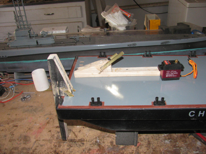
Push bars in place.
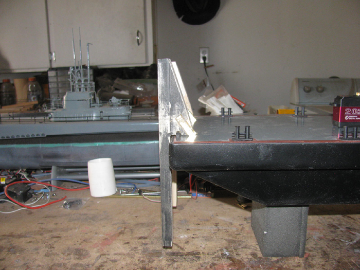
Push bars in the raised position I hope to achieve.
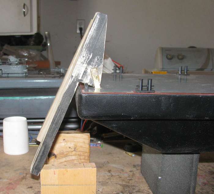
A look from the side and back.
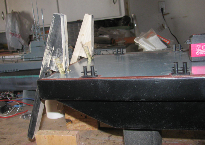
December 31th =================================================
Just because it is the last day of the year, I can not violate my 10
minute rule.
"I must put at least 10 minutes every day during a build."
I got in about 20 minutes.
Maybe 30 minutes.
I files the shims on the front of the push bars that make them 90 degrees
to the water when touching the barge bow.
I test fit the push bars until they sit at the correct angle.
The push bars sit about 1/8" above the deck at this point.
I can either file the slot in the deck longer towards the front or
I can add plastic shims under the push bars.
I chose putting plastic shims under the push bars and leaving the tight
fit through the deck to make it harder for water to enter the barge hull.
I think a little silicone will seal the control arms through the deck
once I get all the linkage and servo in place.
Made the shims and glued them to the push bars.
As always, currently on the work bench in clamps while the glue cures.
There is today's minimum time in the shop.
I do not go out on New Years Eve.
I live in the desert and it is a long ways to anything.
But not to worry.
A few friends and I meet some where within 80 miles for a long lunch.
Been doing this for years.
Today was no different other than the group is getting smaller each
year.
Some move away.
Some do not make it to the end of the year.
As long as I can be there, I will.
These are the few friends you can count on one hand to be there if
you every need help.
Everyone be safe tonight and tomorrow.
January 1st =================================================
This afternoon I started on the linkage mounts.
Cut lots of wooden blocks. (poplar wood)
These will support the push bars and the control linkage.
Test fit for look and placement.
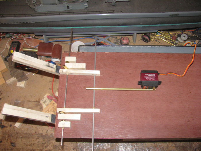
Disassembled and removed the shaft bushings.
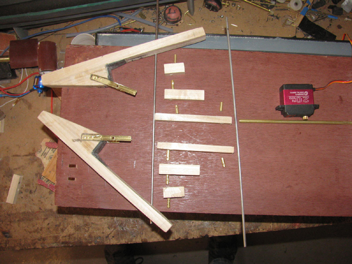
Applied glue to each bushing and slid each block on to the long control
rod to align the parts
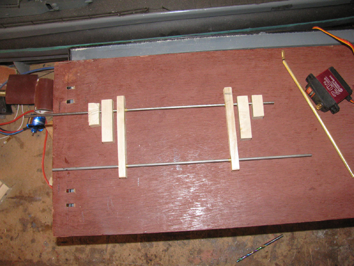
Next I applied glaze to the pusher bars so I can sand them smooth and
hid the sanded low spots
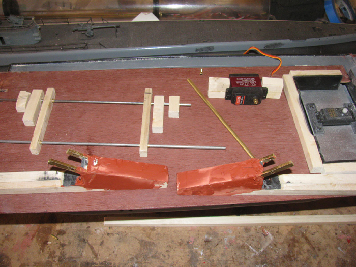
Tomorrow, I will assemble everything to locate where on the underside
of the deck they will be glued.
I will draw on the deck with a pencil so I know where to remove the
primer to bare wood.
January 2nd =================================================
Sanded the push bars.
Need a little more glaze in a few spots.
All parts ready for glue.
The under side of the deck has been sanded down to the bare wood so
the glue can soak in.
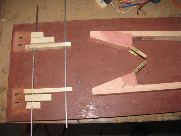
Glue has been applied and parts put in place with the push bars also
in place as spacers.
Clamped to work table.
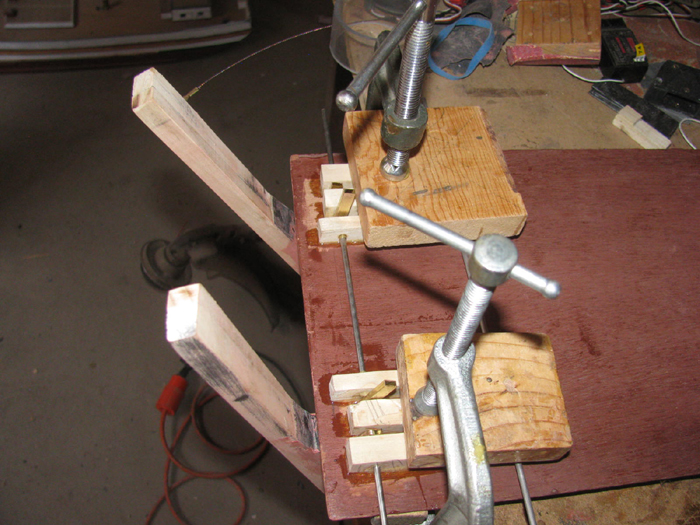
http://www.scratchbuildwithjohn.com/
Removed the push bars by cutting the glue and rotating the shaft.
I then cut and filed the glue in between the bushing blocks.
Took some time but I got a smooth fit between the block for the pusher
bars.
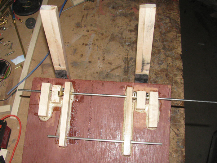
I sanded the glaze on the pusher bars.
Didn't want that to get in the way of fitting the bars between the
blocks.
I hand fitted both pusher bars.
It required making the deck slots longer towards the front.
It required filing on the shims to get the pusher bards to sit flat
on the deck and get the 90 degrees to the water line.
Weather was nice outside and in the shop.
This fitting process took me almost 2 hours.
My fingers are tired and hurt from pinching the parts while filing.
I did get both pusher bars to sit correctly with just the weight of
the pusher bars.
There is a lot of glue that squeezed out from under the bushing blocks.
I plan to leave it and I may add to it .
I cut 2 pusher bar shafts.
Found a small bag of 1/8" brass wheel collars to hold the shafts.
I will need to get more to make the control horns from the secondary
shaft and to the servo.
I will use 2 wheel collers per control horn.
This servo has 20 kg of torque.
The arm that came with the servo is a steel arm with a split and 2
tightening bolts.
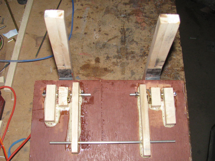
Worked on the 2 plastic pieces that will go on the large pulley wheel
to remove the slack from the steering cable.
I found a small stainless bolt while looking for stainless Allen grub
screws in my parts box.
Bad news, I spilled the grub screws of which most landed on the work
bench but at least 3 got away to the floor.
I could not find them.
Must be time to clean the shop and the floor to find the years lost
parts.
January 4th =================================================
Sanded the push bars.
Drilled holes for the control linkage.
They are ready for primer and paint.
I don't have any flat bar brass so I decided to make the control linkage
out of round brass tubing.
Cut to length.
Cut a slot in to both ends.
Opened up the slots and flattened the ends so the rectangle tube fits
down in the slot.
Remembered I got things to do in town.
Brought the primer and paint in to the house to warm up.
The shop is still down about 40F.
I think there will be time this afternoon to prime and paint.
Might even get to drill the holes in the linkage pieces.
Looking at the photo above, I might even get a coat of primer on the
under side of the deck where I have been working.
Back in the shop.
Primed the pusher bars.
It is not warm enough to dry the primer.
I will let dry overnight before painting black.
Back to the control linkage.
Made more parts and started fitting them together.
Using brass 1/8" tubing and rod as pins to hold it all together I have
mocked up the linkage.
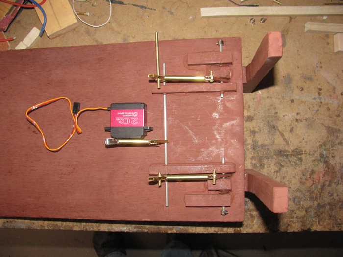
The servo will turn the long stainless through rod through a single
horn at the center.
The long rod will turn 2 horns that will push the pusher bars horns.
Lots of wheel collars to solder .
1 on each side of each horn. (need lots of strength)
The push rods are made from 1/4" round tubing with the ends split
and flattened.
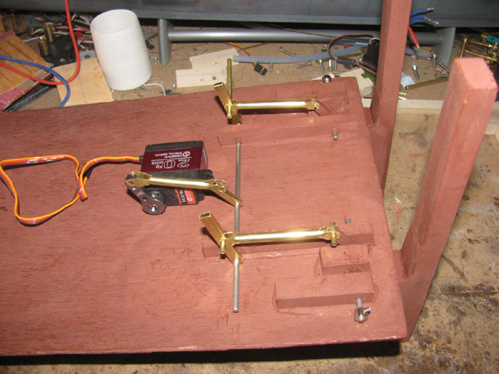
I need to make the servo aluminum mounting bracket.
I think the mounting bolts will go through the deck.
Before I mount the servo, I need to get the electronics up and running
so I can see the servo horn movement so I can align it for better torque.
Might have noticed, I did prime the underside of the deck. (looks better)
January 5th =================================================
Not able to get out to the shop.
Just too much to do.
I spent way to much time looking to brass wheel collars.
Now that they are hard to find, it was finding a vendor who's web site
that could deal with me not having a physical address for billing or delivery.
Most people do not understand those of us that live out in the desert
where there are no street address and mail only is delivered to the post
office box.
I ran the cost numbers for those with free shipping and those with shipping
charges.
Turns out Amazon wins again.
They had the same parts from the main vendor for a little more than
the vendor but they have a fixed shipping cost that is 1/4 the original
vendor.
Cost of parts is more the shopping is much less and that works out
that it will cost me $.32 more from Amazon but they take my billing and
shipping addresses.
Parts are on the way for $1.99 shipping.
Okay, I slipped out to the shop.
I sanded the primer on the pusher bars.
2 little spots to glaze again.
The long seam on the front of the bars where I jointed two bars to
make one.
On both pusher bars, I needed to file a 3/4" line gap where the glue
did not push out when squeezed together.
Applied. Now to let them dry.
I will paint the pusher bars this afternoon.
Basically, I am finished with the pusher bars until the wheel collars
get here and I can finish the linkage pins.
What can I do that will not take much time?
Oh, I can touch up the red paint on the fire hose reels I repairs the
valve handle on.
Done.
Took longer to clean the brush than to paint.
When I go out to paint the pusher bards, I will look for wire to wire
the pod motor.
I hope to start assembly of the motor pod tomorrow.
Today started out with me being confused.
I thought it was Saturday.
It was 10:30am before I realized it was Tuesday.
Got to look at the on screen time and date stuff once in a while.
oops.
--------------------------------
I was able to finish the other stuff and make back in to the shop.
Sanded the pusher bars.
The sun is out and it is warm outside.
Out to the outside work bench. (it is steel and is very warm)
I got the first coat of paint on the 3 back sides.
In to the shop.
I cut stainless steel pins for the linkage.
It turned out that the stainless `/8" rod for the shafts and pins was
not a shaft at all.
It is a tube.
It has a small hole all the way through it. 12".
Good enough for what I want it for.
Laid all the parts out on the deck.
Will continue this when the wheel collars get here.
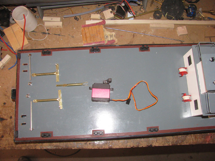
This is a rescue barge and I do not want it sinking at any time.
I have big blocks of white foam from my giant airplane days.
10' to 15' wing spans.
Was also going to build an experimental airplane but life toss that
out.
I measured the inside of the hull.
With my trust old thin hand saw, I cut a piece out of a big block.
Cut the for and aft bottom angle.
I measured for the rudder servo and the pusher bar linkage.
Cutting in to the foam block for the linkage parts.
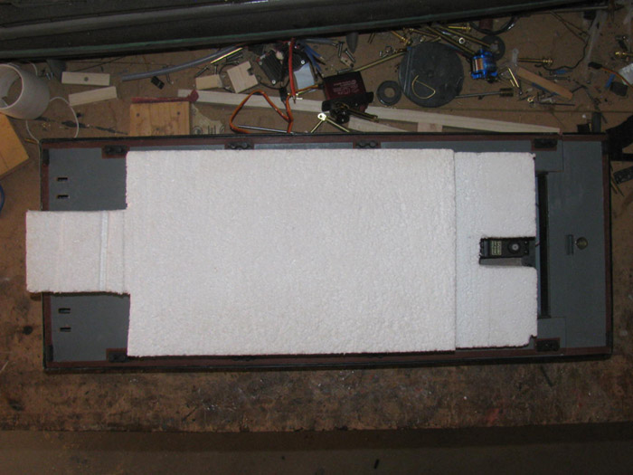
Got the needed angles and cuts in the foam and it slips right in under
the electronics tray.
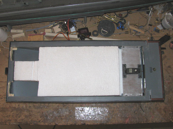
While doing this, I would go out and put another coat on the pusher
bars.
There is more cutting to do but not until I get the equipment installed
and I know exactly where to cut recesses in the foam.
Still painting the pusher bars.
Okay, touch up the fire hose reels with black handles.
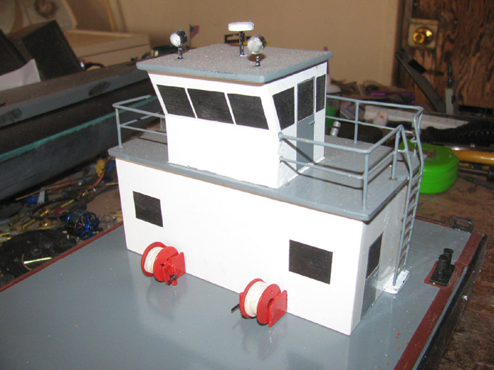
Temperature is starting to go down.
Finished painting the pusher bars.
Set them in place in the deck for a photo.
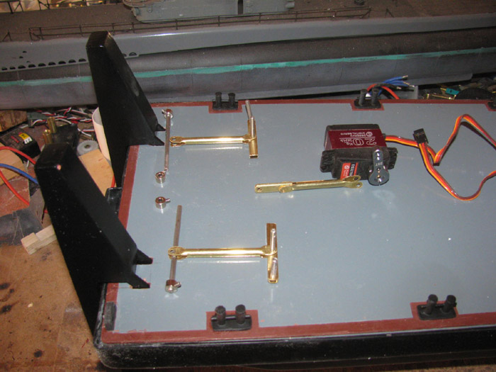
Not sure what I will do tomorrow.
I think I have a couple hours in the afternoon.
Won't know until tomorrow.
Could end up with more time.
January 6th =================================================
Okay, what to do?
How about mounting the speed controller and Rx.
Set the deck on and mark the access hole under the deck house so I know
what my limits are for the electronic parts.
I put the large servo pulley on and I can now see where to trim the
water dam.
I need to cut away about 2" wide on the back side for the pulley to
go over the stern block.
Dremel and Roto Zip bit does this is a matter of seconds.
File and sand it so there are no sharp edges.
I have 3 speed controllers.
Which one.
The choice is easy.
The one I find the programming instructions for first will do.
Looked under the work bench in a little tray where I put parts taken
out of boats during modifications.
I know they work and this is where the speed controllers came from.
I know they work because they came out of the several mods on the Skipjack.
Wait! There is a folded up instruction paper in this little plastic
parts tray.
Instructions for the 30 amp speed controller.
It is the middle one in size but there is plenty of room for it.
I have a winner.
Found some high temperature silicone covered wire that will do for the
power down the rudder tube to the motor.
It is twice the size of the short wires coming off the motor. Not a
problem.
Soldered short lengths, (long enough to get to the speed controller
with extra for allowing the rudder to turn 180 degrees.
Made up a short connector out of two wheel collars and found two 1/8"
long stainless grub screws.
Drill out the wheel collars to acept the brass tube with 1/8" inside
diameter.
Measure and drill hole through the brass tube for the grub screw to
go through to reach the motor and propeller shafts.
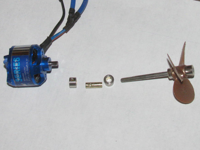
The wheel collars are side by side and fit inside the tail cone.
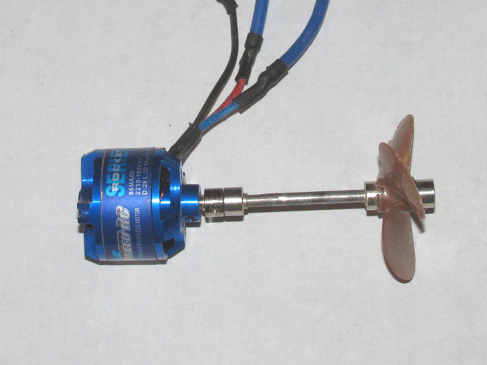
I have to get this to fit inside the pod tail cone.
(turns out, the connector with 2 wheel collars fits inside the pod
and does not stick in to the tail cone)
Test fitting the motor.
The mount is slightly off center in the up and down direction.
Adjusting the 4 screw tightness did not get the motor to move enough.
After several test fits, I got out the 1/4" drum sander and Dremel.
I sanded the inside of the pod housing on the bottom section.
Tested again and it seems I got it very close.
Took the Exacto knife and cleaned up the sanding marks.
That did it.
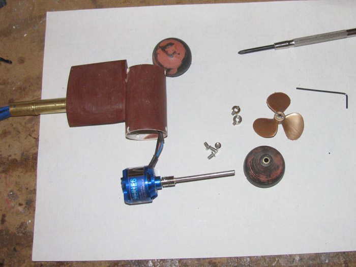
Closing up the pod.
Turns out the 3 screws that were to hold the pod ends on change the
straight line enough the shaft would not turn.
Thought about it and came to the conclusion, I do not need the screws.
A light coating of silicone glue will hold it on and seal the pod from
water.
I though I needed the screws so if the motor heated up and the air expanded
the ends would pop off.
I did not think it all the way through.
The rudder shaft is open at the top down in to the pod. (wires)
It is not a closed system.
It is vented.
No pressure build up.
Using the silicone glue will seal the pod and the silicone should let
the pod caps move a little during operation and the shaft should not bind.
The pod is currently sitting on the bench while some CA glue cures.
I filled in the 6 screw holes and will file them down later.
Install the rudder and pod in the stern block.
Figure out how I want the wires so they can let the rudder post turn
180 degrees.
Then mount the speed controller.
----------
At this point, once I put the motor pod on the barge, I will need to
make a stand for the barge.
The pod sticks down below the barge bottom by about 3" to 3.5".
And I think I made the pusher bars the same depth to start with.
----------
Make up battery power wires and plugs.
Might as well charge the battery so it ready for testing.
I want to test the system to see if I can get the pusher bars to move
up to down by using only the control stick slider adjustment.
If I can, I can use a 4 channel Rx.
If not then I have to steal the GW 8 channel Rx to use channel 5 or
6.
I have two 8 channel Rx but they are 72mhz. (yes I have the 72mhz Tx
module as well)
January 7th =================================================
This afternoon, I sanded the CA that I filled the bolt holes with on
the motor pod body.
Painted the pod below the waterline including the nose and tail cone.
(guess where the waterline might end up)
Let it dry.
While it dried, I wired up the main power from the battery to the speed
controller.
Required 3 plugs and 2 wires about 6" long.
Checked all in the hull and soldered the plug ends on the wires.
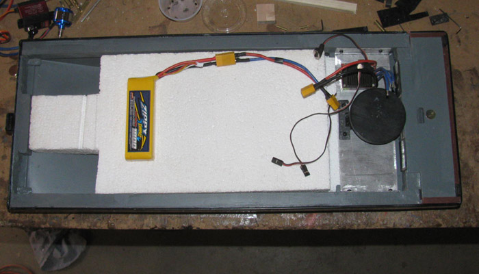
Finished this and went back to painting the above the waterline on the
pod assembly, hull black.
I am going to let this dry completely before putting the motor back
in the pod body.
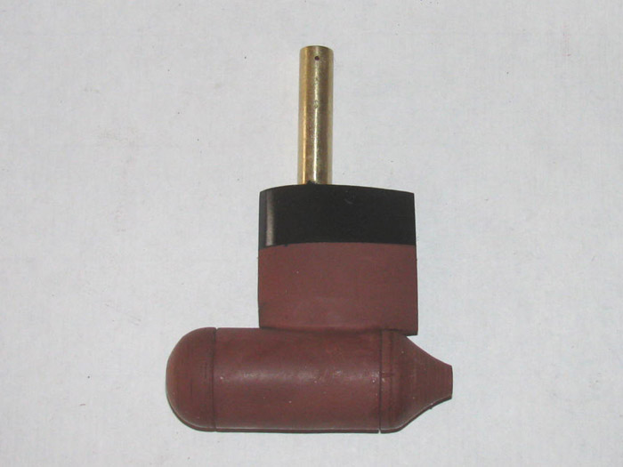
January 8th =================================================
The motor has been installed in the pod housing.
The propeller has been put in place so I can measure the propeller
shroud.
The should was made out of a pvc water pipe connector.
I had sanded the inside until the propeller fit.
Today, I wanted to fit the shroud over the propeller and see where to
cut the length.
The connector is 2.5" long.
After I sanded more on the inside to get the propeller to pass through
without touching, I fit it to the rudder and measured the shroud.
I had already cut a notch in the shroud for the back of the rudder.
Should have waited but I didn't.
To get the propeller shroud in place and look the way I want it, compared
to the many photos I looked at, I needed to cut 1/4" off the front and
some off the back.
The shroud is now 1 5/8" long.
After cutting to length I needed to turn the inside some more and shape
the outside.
Out to the tool shed and on to the drill press.
No I do not have a chuck big enough to put the connector in.
So like last time, I tightened up the chuck with nothing in it and
then using electrical tape, I wrapped the bottom end of the chuck until
I could push the connector on to the tape and it was tight.
This works well to spin the connector.
Now with Exacto knife to cut inside plastic out and the outside as
well, I worked the inside to get the propeller to fit and then I shaped
the outside to an airfoil look.
Sanded with fine sand paper before removing from drill press.
Back to the shop.
I had a piece of plastic on the bench that was several layers thick.
I have been moving it around for several days.
I had made this part way back when.
Now it is time to cut it in to 4 pieces and shaping.
These parts will become the 3 shroud support pieces.
From the pod body to the shroud.
I got them cut and shaped roughly.
I have to drill bolt holes before going any farther.
Going to work on that tomorrow.
Today I was able to get 1.5 hours in the shop.
January 9th =================================================
Early start this morning.
My plan is to get the motor pod assembled.
Here I have drilled the shroud and installed the 3 shroud supports to
the shroud.
The propeller is there to make sure I center the propeller and there
is clearance.
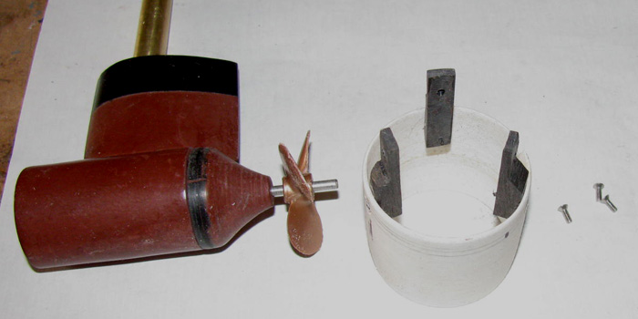
Another view of the motor pod and shroud.
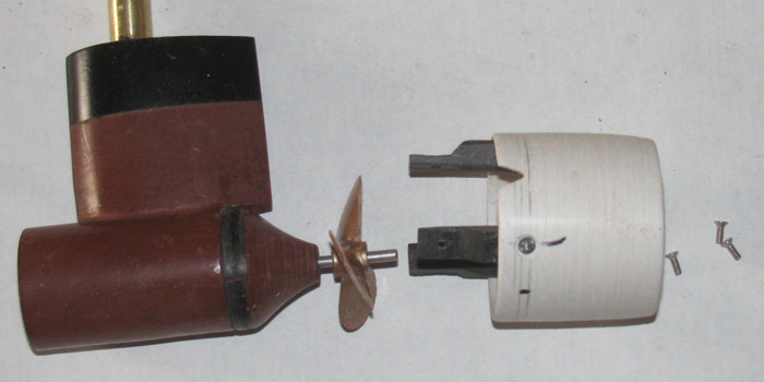
The propeller shroud has been installed.
I found that a 1/4" drill bit was the correct spacing from the pod
to the shroud.
Drilled, tapped and installed bolts to hold shroud to the pod.
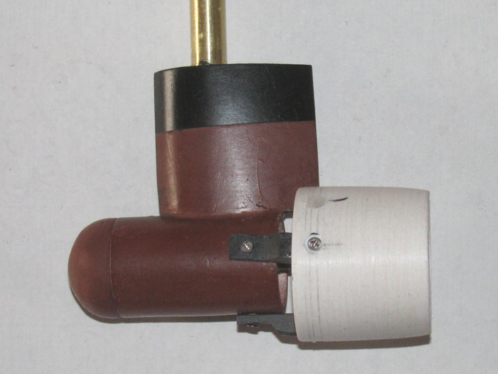
A view inside the shroud showing propeller clearance.
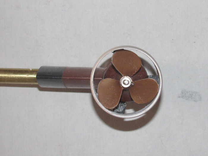
Now to disassemble it all and shape the supports to make them a little
more streamlined.
Got to remember to number them so they go back in the same spot.
Also I have to recess the bolts at thepod end.
This was all drilled by hand with no jigs.
----------------------------
Disassemble.
Shroud supports filed and shaped.
Shroud and supports are now painted hull black.
The nose and tail cone have been installed using silicone glue.
I will let the silicone cure over night.
I will re prime the motor pod.
Then I will install the propeller and the shroud on to the pod.
This should complete the motor pod drive and be ready for testing.
January 10th =================================================
I started by checking the pod for leaks.
This was simple.
I just had to draw a air out from the top of the rudder post.
I could not draw any air at all.
Now to continue with the assembly.
Right after I paint the pod and shroud.
Got that done.
Here is the pod installed in the stern block.
The hole you see is for the shroud.
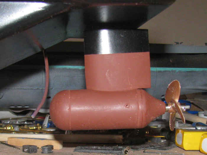
Here the shroud is slipped on to the pod.
I have not yet put the bolts in.
I want to get another coat of paint on the shroud before installing
the bolts.
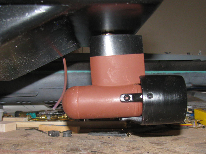
With the pod installed the top pulley is in place.
The keep ring is in place.
I can now start on the steering cable.
Drilled some holes for the cable to go through the sides of the pulleys
down in to the pulley groove.
I measured for the cable and cut a length.
This cable is what I use as rigging on sail boats.
It is fishing wire leader at about 250 pound strength.
It should do fine.
The cable tensioner is done but not installed.
I want to finish painting before I install the cable and stretch it
to tension.
The plastic pieces will mount on top of the large pulley at the front.
The adjusting bolt with be on the outside of the pulley so I can reach
it with a small screw driver.
I probably could have set it on the pulley for the photo.
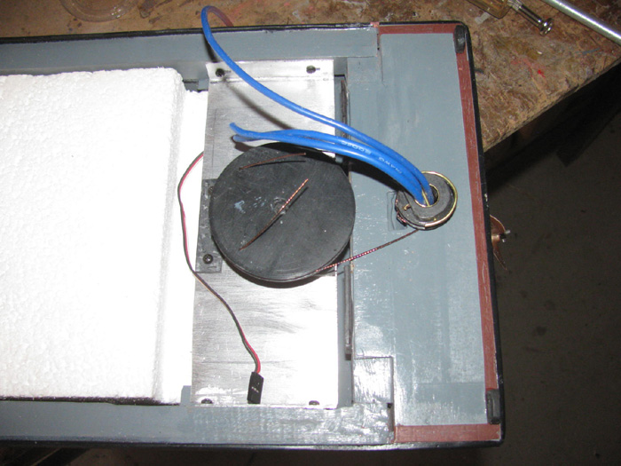
Later today, I should get the shroud painted and mounted.
Yea, I am going to have to build a stand before I damage the pod and
shroud.
I will measure the barge and see if I have enough lumber to make a
stand and maybe a transportation box.
January 11th =================================================
In the shop after noon.
I am going to see if I can use the 5 channel Rx I found in my parts
box.
It was given to me.
I soldered the speed controller to the motor wires.
I can now get power to the Rx by the 3 wire connector.
Plugged it in.
Also plugged in the rudder servo so I could see if the Rx was connecting.
I tried to get the 5 channel Rx to connect to the Tx.
Problem for me is there are no instructions.
Another problem for me is I only know how to turn on the electronics
and work on simple issues.
Speed controller to e is not simple.
There a beeps that I can not hear or they are too close together for
me to break down.
This Rx just beep continuously.
No matter what I do, it only beeps none stop.
It may be a matter of Tx and Rx not being compatible.
My solution is to get my 8 channel Rx that goes in my GW which happens
to be all a part right now.
Plugged it in and it came to life.
Checked the Tx channel percentages and set them to 100%.
Rudder servo, not connected to rudder control horn, works fine.
Next, I tried the speed controller channel.
Forward, good.
Reverse works but is slower that forward.
Had this issue when this system was in the Skipjack.
It also requires a pause at neutral to change direction.
Reason I took it out of the Skipjack.
Anyway, it works correctly.
Now to try the very high torque servo I will use for the pusher bars.
Holy crap!
It works and the torque is enough to push start my real truck.
Okay, testing works as it is suppose to.
Even the servo directions are correct.
Next is to install the speed controller and Rx on to the electronics
tray.
Clean up the wiring.
Shorten some of the wires and resolder.
I tried to take a photo of the propeller turning.
Did not work out.
The camera actually stop motion the propeller.
Looks like a stopped motor shot.
The propeller is turning at a speed that my eyes sees only a blur.
Camera stopped it. (I am amazed)
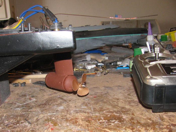
Here are the electronics sitting on the deck.
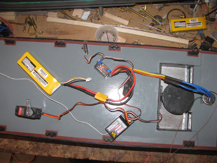
January 12th =================================================
After think about the speed controller I have( 3 of them), I know from
running it in the Skipjack, I do not like the neutral pause to change directions.
I order 2 new speed controllers that do not have the pause so they say.
It is going to take some time to get here. (4 to 6 weeks)
Out to the lumber pile.
I found enough plywood to make all 6 sides of a transportation box.
Measured the barge again t make sure of the numbers.
Cut the plywood panels.
Looked around for trim boards.
I have about 3' which will not do.
I need 42' in all.
Next time I am near the lumber store, I will get what I need.
Back in to the shop to work on the steering system.
I got it all measured out and ready for testing.
Began the testing.
It was working very well up until, the cable started jumping off the
pulley groove and falling down on the shaft.
This will not do at all.
Looking at the cable while running the servo, I see the servo turn
the large pulley and take a strain on the cable.
For an instant the rudder shaft does not turn and the cable on the
opposite side becomes slack enough to jump off the small pulley.
Farther looking says it is not slack at all.
It is the cable is so stiff that it does not bend around the pulley
and then jumps off.
The cable is 250# fishing leader wire.
It does not have to bend to do the job it was made for..
I tried bending the wire in to a curve.
Seemed like it would work.
The cable goes around the pulley but the curve is so stiff it comes
off the pulley as it turns and is still curved.
This will not do.
So I removed the cable and I am going to test some pre stretched braided
nylon string.
Rated at 200 #.
Okay, I tried to stretch it.
I could not.
I am going to try this on the pulleys.
But I think I will make some small changed to the pulleys.
I will remove the bottom edge of the pulley by turning it to the size
of the groove.
Then I will glue another piece of sheet plastic on and make the edge
wider.
Maybe this will catch the string before it can run off the pulley on
the bottom.
Pulleys have been turned are now in the vise with the new sides on them.
January 13th =================================================
Changes to the pulleys have been made.
I have fitted them but not tested them.
Assembling the transportation box has started.
The panels where cut yesterday.
Today, I cut most of the trim boards.
Before I can cut any more, I need to assemble the sides and ends.
So, clamped on the outside steel work bench I have the 2 sides with
the top edge trim in place.
Building these boxes is time consuming.
They are glued together with no nails of screws.
I have to clamp and let cure each trim board.
Takes lots of clamps.
I can do 2 maybe 3 panels at a time.
It will take a few days but I am now waiting for parts to start showing
up.
End of month for some and first part of March for others.
January 14th =================================================
More assembly of the transportation box.
I cleaned up the excess glue from yesterday.
I have the 2 sides glued and clamped.
In to the shop.
Thought I would install the shroud.
Looks like I need to do some fitting.
That will have to be later today.
Got things to be done away from home.
-------------------------
January 16th =================================================
Transportation box panels and trim.
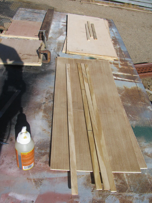
Assembly of end panels.
Gluing trim boards on.
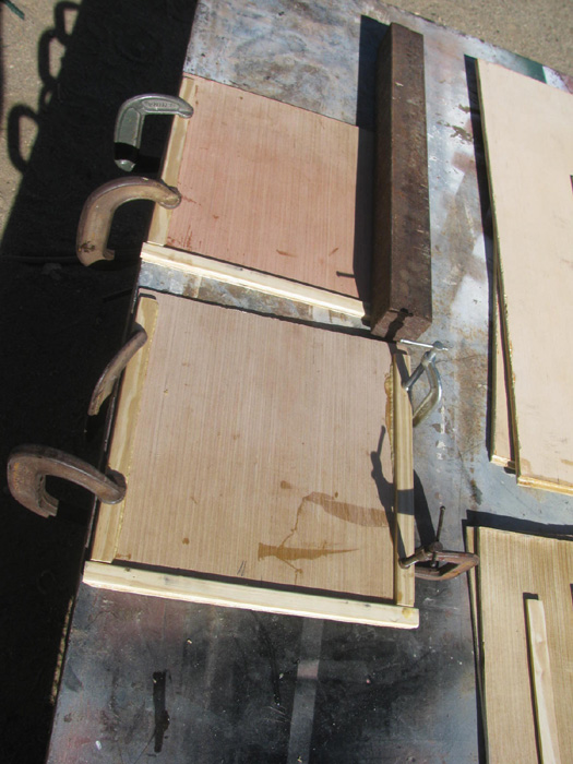
I have to let the glue cure over night. (15 to 20 hours)
So in to the shop to find something to do.
I received wheel collars so I might as well start assembling the pusher
bar linkage.
I have not started the soldering parts.
That is next.
While assembling these parts, I realized I have to get more stainless
grub screws.
I will assemble with the steel screws.
That way I know I have all the linkage parts made.
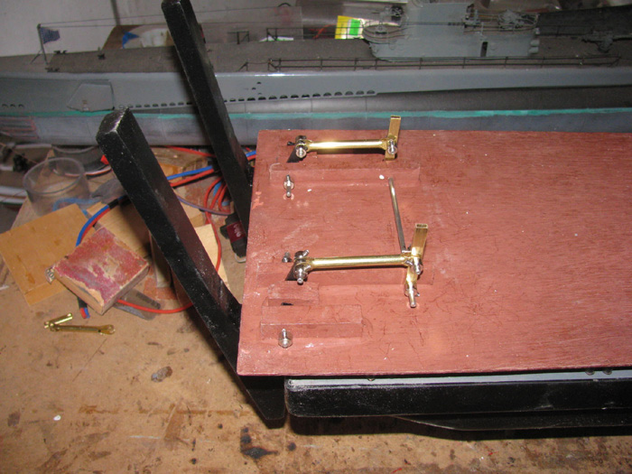
January 17th =================================================
This morning, I assembled the lid panel.
It requires an inside frame besides the outer trim.
It required almost all my clamps to hold it together. (16 in all)
I did the 2 side panels as well. Each required 2 end trim boards.
Everything is clamped and now the waiting to cure.
January 18th =================================================
More work on the transportation box done.
So many small parts to glue on making it hard to continue as the glue
needs to cure before disturbing the parts.
15 hours minimum.
I did measure for the box lid stand.
Cut all the parts and start gluing them to together.
Going to town and while there, I plan to pick up some bolts, tube of
glaze, paint and some hinges.
===============
Went to town.
I just came in from the shop.
Got everything but the hinges.
Oh well. Next trip to town.
In the shop for a few minutes.
Thought I would do something.
Looked around for scrap aluminum plate. (my old 25MPH sign)
Found a piece that looked like it was cut for the pusher bar servo.
Cleaned it up with the disk sander.
Measured and put a 90 degree bend in the plate.
Cut a notch for the servo.
It is ready for drilling holes for mounting the servo and to the under
side of the deck.
January 19th =================================================
Got out side to work on the transportation box.
Cleaned up the glue that squeezed out from under the parts.
I ran the lid through the table saw to straighten the underside frame
that drops in to the box as a guide and strengthens the lid.
Took the parts in to the shop.
At this point I quit.
My fingers no longer work.
I am going inside to get warm.
January 20th =================================================
I am still working on the transportation box.
Gluing parts together.
I put the boards on the under side of the lid that will hold the hinges
for the stand pieces.
The stand pieces are done and ready to be painted.
It is windy and I am working outside on the metal work bench.
With the wind and cold it says 41 degrees on the gauge.
And the sun is covered by clouds.
My hands can only take so much.
In to the house I go.
January 21st =================================================
Early this morning, I fitted and glued the two ends to one side panel.
This way I can use my 2 aluminum "I" beams to hold everything square.
They are at least 8" tall and 6" wide.
Makes holding square and lots of room for clamps.
Had to go to the big city.
A store got a shipment of the printers I have been looking for, for
2 months in.
I was looking at their web site very early this morning where it showed
no printers within 250 miles of my location.
I was reading the spec when the page change to "In Stock".
Jumped in my car and off I went.
It is only 70 miles round trip.
Turned out to be next door to a Lowes hardware store.
I needed 1 more 8' trim board to finish the transportation box.
Yes, I bought enough but a couple of mistakes destroyed some of the
trim and I had to replace it.
Got home and back out to the work bench.
Cleaned and glued the 4th side of the box.
Lots of clamps and "I" beam.
I did some measuring and cut the lid to the box numbers.
Next will be the bottom panel.
Then the last of the trim boards.
Sanding will follow.
Lots of sanding.
To clean up the glue that squeezed out from under the trim boards.
Then the start of glazing to clean up the rough panel edges.
They were not rough when I started. (oops)
While in town, I picked up parts at the post office.
1 more order to go. (new speed controllers)
It is suppose to rain tomorrow.
Maybe I can get the pusher bar linkage soldered together.
January 22nd =================================================
The weather has turned cold here.
It looks like the high for the next week is going to be 48F or below.
Also says snow next weekend.
Not good for gluing wood panels together.
But, I went out to the shop and turned on the heater.
Got it up to about 60F so I decided to continue putting the transportation
box together.
I had put the lid trim on and clamped it down to the work bench.
Either later today or tomorrow, I will do the bottom panel.
That will complete the box.
Then the sanding and glazing begins.
(That reminds me. I need to go out to the shop and turn the heater off)
January 23rd =================================================
High today is 40F with snow this afternoon. (maybe)
Heater is on in the shop.
Right now it's 50F in the shop.
More trim cutting and gluing.
Thought I was done until I turned the box over.
More to do.
Glued and clamped.
Maybe more this afternoon.
======================
Afternoon!
I was able to trim the excess glue that squeezed out after clamping.
It has cured enough to have expanded and is hard enough to cut but
still soft.
I drilled the lid for the hinges.
Using only the center hole I screwed the hinge in place.
This let me check the stand to be at a right angle to the lid.
Had to do some adjusting.
A little, wood removal on the lid for the hinge barrel.
Got it.
Made up the cable with wooden dowel ends that goes between the two stands
to keep them from falling over when the boat is on the stand.
The rain has started and it is turning cold.
That's it for today.
January 24th =================================================
All the parts of the transportation box have been glued in place with
assorted clamps.
After trimming the excess glue tomorrow, I can start sanding.
While in the shop, I measured and hand drew a profile image of the rescue
barge.
Brought it in to the house and made 3 copies.
With the 3 copies I can cut out the sheet plastic parts and shape them.
I have an extra aluminum badge plate I can use on the bench.
All I need now is a day that is warmer so I can do the sanding outside
on the metal work bench.
==================
Took the drawings out to the shop.
I cut out 2 of the 3 badge pieces.
Did the shaping of both.
The third pieces is mostly a straight long rectangle so I have not bothered
with it yet.
The 2 shaped pieces are glued together and in the vise to cure.
Of course I thought I had all the pieces on the transportation box.
Well, like always, I did not think about the 2 short pieces on the
bottom at the ends.
They are fitted after the bottom panel and trim is in place and the
sides are in place.
These 2 pieces are sitting on the bench ready to go on once I can turn
the box upside down to work on it.
All in all the transportation box is coming along.
January 25th =================================================
Woke up to about an inch of snow on the ground.
Means the temperature is going to be 32F.
Had to go out to the shop early for some stuff in the house.
Turned the heater on.
An hour later I went back out to the shop.
It was warm enough to do a little work on the transportation box.
Trimmed the excess glue from yesterday.
Looked the box over carefully and found I needed a wooden trim strip
o each end.
Cut the trim strips and fitted them.
Got the glue from the house where it lives to stay warm.
Glued the last 2 strips.
Sat down on my wooden milk crate and started shaping the plastic box
badge.
I have the first 2 layers of plastic sheet sharped.
Made the third layer piece and bonded in to the other 2.
It requires just a little shaping.
Well actually, I just need to file the upper edge down to the deck
level of the other 3 layers.
I was going to go out to the steel work bench and clean p the aluminum
badge plate.
Stepped outside to a nice clear and cold 33F.
Now 4 hours later, it has warmed up to 38F.
I have decided I will wait for another day to work outside.
Weather says, Thursday will be above 40F. Yippy! I think.
With the weather so cold I think tomorrow I will work in the shop and
make the Tx case badge.
Transportation badge is 6" long and the Tx case badge is 3" long and
only 2 layers of plastic sheet.
A little progress every day.
January 26th =================================================
Weather is wrong today.
That is a good thing.
Weather says 36F to a high of 39F.
The sun is shining.
The temperature is 48F.
And my hand are doing fine.
A hat and jacket and I am good to go.
First I am going to finished the transportation box badge.
There was very little to do that a file and knife couldn't do.
After finishing the plastic badge, I finished the aluminum backing
plate.
This is what I ended up with.
It still needs to be painted.
Badge flat black and the complete unit cleared.
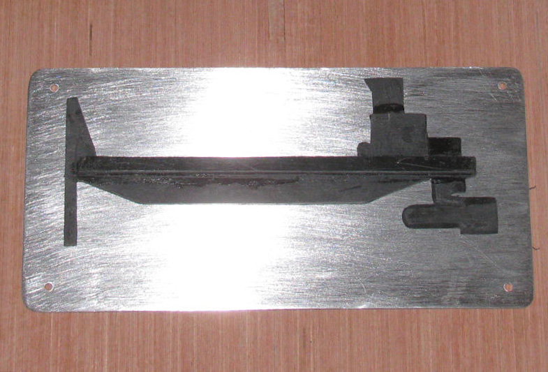
Started the smaller badge that goes on the Tx case.
Drawings made and glued to plastic sheet.
Next step will be to cut the profiles out.
After the glue cures.
On to the transportation box.
Trim the excess glue from yesterday's work.
While I have the belt sander out and in the work bench vise, I thought
I would do the sanding of the trim.
Got that done but I broke a belt and had to use a new belt.
Far too aggressive.
I tried to lightly go over the wood but still to aggressive.
Got the palm sander out which had finer sand paper on it.
Went over the trim to remove the deep marks.
Okay, that went well.
Might as well sand the panels to remove as much glue spill as I can.
Got most of it but needed to use the end of a bigger file to scrape
the glue down.
This is good.
I like what I ended up with.
There are marks showing but the glaze will take care of that.
Transportation box with barge sitting on it.
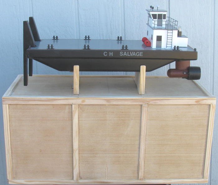
Went to town and bought stainless bolts for the badge plate.
As it got cold while I was gone, I decided to bring the badge plate
inside the house where I could work on it and stay warm.
Printed out a 100% scale template for the lettering.
I got the vinyl letters out and Exacto knife
Started laying down the letters.
This what I have.
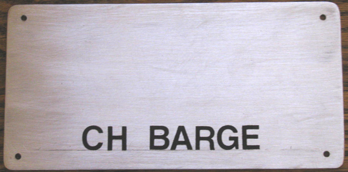
Tomorrow I should be able to get the badge painted and mounted on the
back plate.
Clean up the pencil marks and clear coat it all.
Bring it in the house to dry.
I did printout a full size test and I made the change to the badge plate.
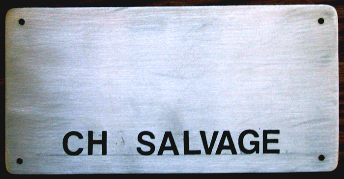
January 27th =================================================
I was in the shop for about an hour and a few minutes.
Worked on the transportation box badge and I made the Tx carrying case
badge.
With the heater on, I even got the first coat of paint on them.
There will be sanding because of the high winds today and the dust
in the sir in the shop.
Top is 4" long and bottom is 6" long.
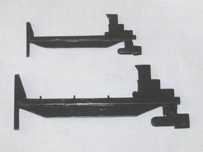
January 28th =================================================
I have things to do away from home.
So early in the shop and turned on the heater.
Got it from 36F to 48F.
I sanded the 2 badges and the badge plate.
Got a second coat of paint on the 3 parts.
Time to start glazing the transportation box.
Me with a new tube of Bondo glazing, I started filling trim joints
and seams.
I did 2 ends, the bottom, the top edge and 1 side.
Can not quite get to the side sitting on the table.
Not a problem.
There is more glazing to be done.
Always 2 or 3 times to get it all flushed out.
I did not take a photo.
Lots of sanding in my future.
This reminds me, I need to make a new sanding block.
The one I have now is worn out and tearing.
----------------------
Back from other stuff.
In to the shop and I was able to turn the transportation box over and
glaze the side sitting on the bench.
Here is the box with all it's glazing.
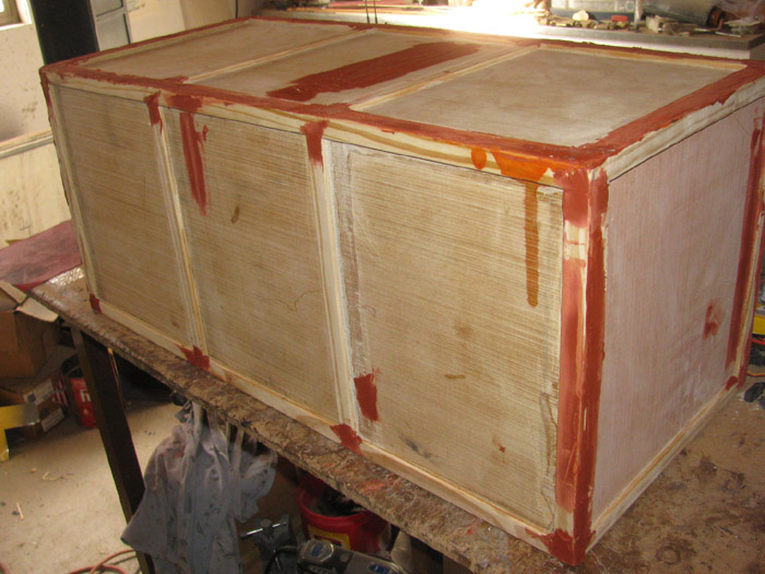
Thought while I am taking photos, I would set the box badge in place
and get it with the Tx case badge below.
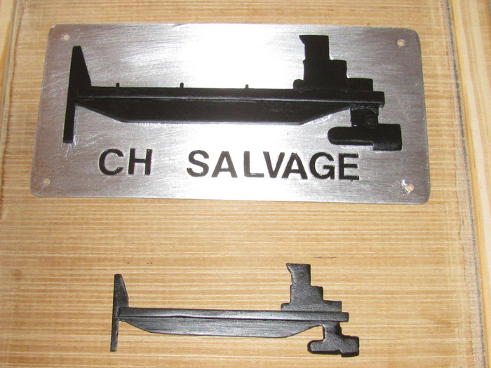
January 29th =================================================
Today the rain that started about 3am is continuing off and on.
This is a cold rain.
Went to town for my biweekly Post Office mail run.
Got the normal expected bills and such but there was a surprise as
well.
The 2 speed controllers I ordered where there.
The order say delivery is to be end of February first part of March.
Opened the package to find 2 speed controllers as ordered.
Only thing is there are no instructions.
So a little web research is in my near future.
My plan was to sand the transportation box glazing.
With the rain I can not do that.
I am not feeling up to turning on the heat in the shop.
So, today is a day off.
I'll make it up tomorrow. Suppose to be sun shine with no wind and a
high of 42F.
I can dress for that and get the sanding done.
-------------------------------------
Looking outside from my desk, I can see the sun is out.
Put on a jacket and went out and looked at the steel work bench.
It is dry.
No standing water and still no wind.
Guess what I did?
I got the palm sander out and put new sand paper on it.
Brought the transportation box out to the bench.
Sanded all the glazed areas.
Took maybe 15 to 20 minutes.
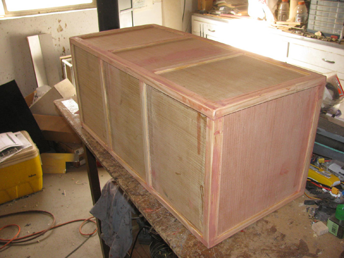
Back in to the shop and glazed a few spots that needed more work.
Looking at the box badge I saw I forgot the exhaust mufflers.
There is plenty of scrap plastic on the floor.
I need a piece about 1/8" wide by 1/4" tall.
Found a piece and got after it with a file.
In a couple of minutes, I had a muffler with pipe.
A very small smear of silicone glue and the muffle is now on the badge
plate.
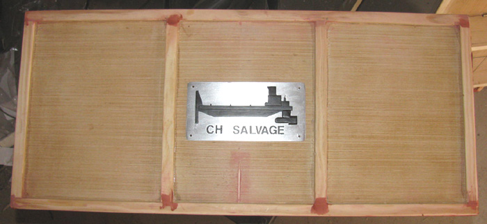
January 30th =================================================
A bit chilly outside but warm enough to get some sanding done.
No wind makes even better.
Weather says 41F but looking at my thermometer on the shop wall says
it is about 54F.
Out to the steel work bench I do.
Sanded the transportation box and the lid.
I see a few more spots to glaze.
Not much.
Just seams that need more filling after the glaze shrank when it cured.
Back in the shop I installed the 4 trim boards that the lid frame sits
on to take any weight that might come it's way.
The lid trim sits on the box top edge but is not very strong should
there be weight on the lids.
These 4 trim boards are down inside the box and the lid frame will
sit on them taking the load off the lid trim boards.
Glazed the few spots.
I will probably hand sand them tomorrow with a wooded block.
Maybe 5 minutes to do it all.
If the weather is like today, I should be able to get the tack coat
of paint on the box and lid.
Might even get the first full coat on the box.
After lunch, I think I will go out to the shop and paint the Tx case
and mount the small badge.
Here are 2 Tx cases with their badges.
Old photo. There are now 3 badges on the left case and 2 on the right
case.
(left case has B-boat, Skipjack and Akula II)
(Right case has Gato and George Washington)
The Rescue Barge has it's own Tx so there will be only 1 badge on the
case at this point.
(this is because if I need to rescue a boat I can not have the Rescue
Barge on the same Tx)
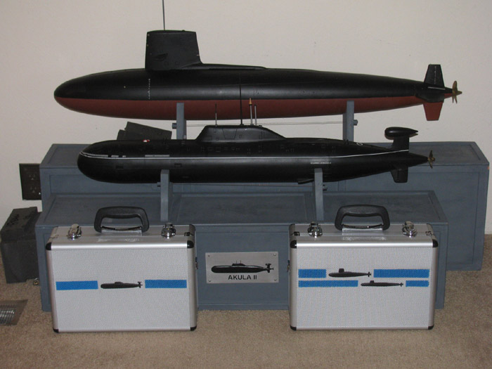
Tx case measured and taped off.
Tack coat applied.
The front has been done.
3 coats of paint on top of that.
This is the back with it's tack coat.
I did the 3 coats of paint but did not take photo.
I will pull the tape tomorrow or tonight.
I brought the case and the badge in the house where it is warmer to
dry.
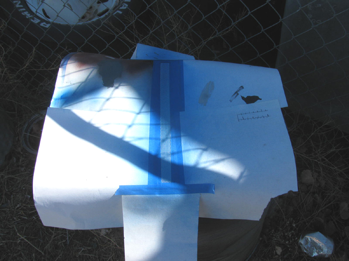
Having mounted the barge badge on the Tx case, I thought I would update
the case photo.
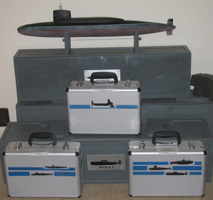
January 31st =================================================
Nice day so far.
No wind, sun shining and 50F at 10:20am.
The sanding is done.
No more glaze needed.
Start up the sir compressor and blow off the work bench, box, lid and
stand parts.
The time has finally come.
Painting.
Took the paint cans out the work bench and set in the sun to warm up.
Picked up the first can and shook.
Opened up to find that the can was used and damaged.
The top was crushed in and it would not spray.
No need to bother with it.
Get second can and shake.
Open it up and it looks okay.
Test spray and it works.
I painted the bottom, both sides and both ends of the box.
Only one side not painted and it is the down side.
Moved on to the lid.
Painted the under side and the frame.
Painted the sides and one side of the stand pieces.
This is a very light coat, hoping to seal the wood so the paint does
not just soak in to the wood and not cover.
Going to let this dry for an hour or so before turning the parts to
paint the unpainted surfaces.
I will paint the inside later.
Basically I use cans that are almost empty to use up the left over
paint.
Then a final coat of the finish color after it all dries completely.
Besides, I have more work to do on the inside.
Figure out where to put the foam support blocks and end stops.
It is really nice to see paint on the transportation box.
-----------------------------
More than an hour has passed.
I started by putting the tack coat on the down side of the box.
Moved on to second coat or first solid coat on the bottom of the lid.
Painted the rest of the box and the bottom last.
Turned the stand parts over and painted the other side.
As of now, there is a tack coat and the first solid coat on all box
outside panels and both sides of the lid.
The stands are painted on both sides. 2 coats.
Had my camera in my coat pocket so here ya go.
Weather has turned cloudy so all the parts have been moved back in to
the shop for the night.
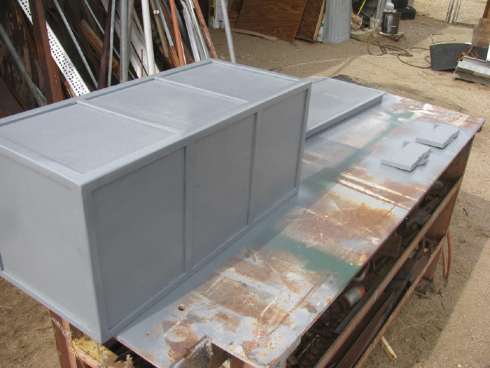
February 1st =================================================
I was in the shop early this morning.
Not to work on boat or box but other.
Looked at the transportation box and lid.
It looks good so far except I missed 4 small trim boards.
They go on top of the lid next to the stand.
This is the first box I have built that has the stand exactly inline
with the trim boards.
There needs to be a short trim piece on each side of the stand.
So I looked in the scrap and found enough trim board to make 4 pieces.
Used the Dremel drum sander to remove the paint where these boards
go.
Cut the trim boards and glued them in place.
Set weights on top of each to hold them down during curing.
I also looked at the box color compared to the other boxes.
Turns out, I have used the wrong color. (looks wrong all glossy)
I used a gloss medium light gray and the other boxes are light flat
gray to match the color of primer gray.
While it is still early and cold, I am going to town for some brass
bolts, thumb nuts and blind nuts for the 4 bolts that hold the lid on.
Will look for the flat gray paint.
I need something else from the hardware store but for the moment, I
can not think what it is.
Must not be important.
Back from town with bolts and stuff.
I have made up the 4 bolts with thumb nuts and installed the 4 blind
nuts in the lid.
Here is a photo of one of the 4 lid bolts. (from Skipjack build)
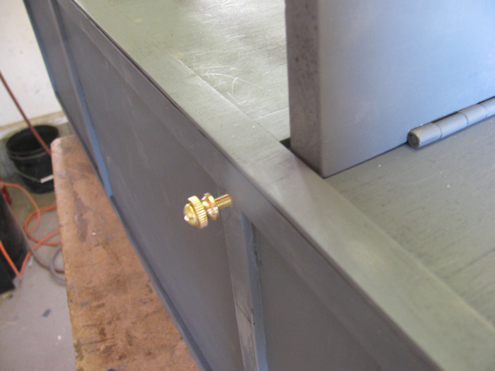
February 2nd =================================================
Learned something this morning.
I looked up the Krylon numbers for their Flat Gray paint.
Looked up a store that said they had 21 cans.
I drove the 27 miles to that store only to find out that the Flat Gray
paint does not exist.
All the numbers I copied down from the Krylon site matched some cans
on the shelf.
But the cans are not labeled Flat Gray.
The cans are labeled PRIMER.
I was not happy.
But I did take the time to read the complete label on the back of the
cans.
A surprise presented itself.
Yes, this is Gray Primer.
But it is Gray Primer/Paint.
It is not clear on the web site or the front of the cans.
But on the back it says the primer will seal the wooden projects and
cure to a hard finish.
Looking at other cans that were paint, they said the same thing.
So, I got 2 cans to test on the inside of the box.
My plan was to paint the inside and then match it to the other boxes
I have already painted in the past.
Originally they were painted with just primer so if they got scratched
or damaged it would be easy to repair and repaint.
But then came along the Flat Gray paint. (that's what it says on the
old cans I have)
Turned out Krylon changed to a paint with primer mixed in for a one
shot painting system.
The primer may very well be the same Flat Gray paint I used in the
past.
Anyway, I have painted the inside of the box.
I have gotten 2 good coats on all the panels.
Tomorrow I will compare this box with the others.
I have options.
Finding this flat gray has not been easy.
How every the Krylon Smoke Gray is every where.
This is what I used on the Barge deck.
It is glossy.
The option is, as the other boxes need refinishing, I use the Smoke
Gray paint and live with the glossy look.
Another thing to consider is the Smoke Gray covers much better than
the primer gray.
The primer gray tend to streak on the overlap passes.
The Smoke Gray stayed wet long enough for the paint to flow out and
level itself.
I do not see over lay passes.
--------------------------
Now for good news.
Tomorrow, I get back to the barge steering system.
Means I get to install the pod assembly on the stern and wire up the
new speed controller for testing.
And I can solder up the pusher bar linkage.
Truth is there is not much to finish on the barge if the speed controller
works as needed.
No pause when going from forward to reverse and back.
I have 3 of those speed controllers.
I was going to give them away.
But I think they may end up in the trash so no one else has to deal
with this strange pause between directions.
If it was small pause no big deal but it is 3 to 5 seconds.
When it was in my Skipjack I tried to learn how to deal with it. (I
hated it)
After several runs I pulled it out and tossed it in the parts box.
February 3rd =================================================
Did more painting on the lid.
The 4 trim boards by the stand.
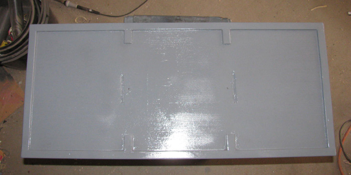
I cut 4 aluminum 90 degree angles for the pusher bars.
Drilled the holes that will allow me to adjust the depth of the bottom
horizontal leg of the pusher bars.
I can go from 3" below the water surface to 7".
I should be able to recover a 6.5" diameter submarine that is on the
surface without issues.
Painted 4 angles pieces, the lower wooden parts and repainted the main
pusher bars.
I will get another finish coat on a little later today.
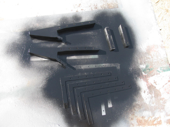
The stainless bolts I planned to use are short.
Next time in town I will get longer bolts.
Tomorrow, I will be in the shop mid morning.
My plan is to assemble the pusher bars and solder the control arms
to length.
This should let me locate where the servo will be mounted.
I will drill through the deck and counter sink the holes for the flat
head bolts.
Then I will CA the holes in the wood to strengthen them.
Note: The primer/paint I used on the inside of the box appears to be
the same color I used on all the other boxes.
When I try to scratch it, it does not act like primer at all.
It acts like paint.
It is hard to the tool and not soft like primer.
While getting bolts, I will get 2 cans of this primer/paint and make
it as box paint for future use.
I ordered gray foam to make stands in the box to protect the barge.
Like I do my submarines.
It has been here a couple of weeks.
Once I get the deck mounted on the barge, I can measure and cut the
foam to fit in the box and the barge hull shape.
Rescue Barge sitting on finished transportation box.
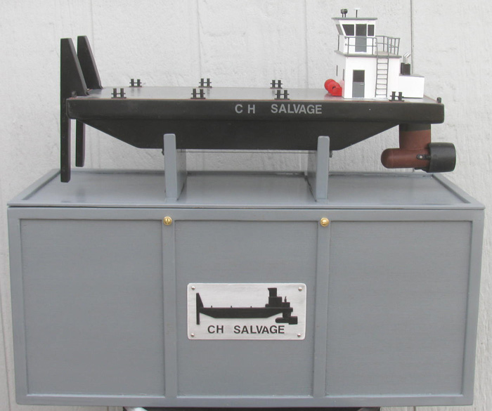
February 4th =================================================
Started by repairing a mirror on the truck.
Took it apart and cut the spring shorter.
The threaded piece in the mirror housing was stripped.
To get the bolt down far enough to reach the existing threads I needed
to get the bolt to drop 3/16" deeper in to the part.
Got that done.
The pusher bar 90 degre angles needed to be trimmed to length on the
bottom leg.
Cut about 1/4" off so the aluminum would not stick out past the wood
piece.
Sanded and painted all the parts again.
Got the push bar linkage parts out and assembled them on the deck to
make sure they went where they needed to go.
Time to prepare and solder wheel collars to the brass rectangle tube
arms.
I used a stainless rod to line up the parts and hold them straight.
Soldering done.
I drilled the servo aluminum bracket.
Then I drilled the main deck.
Reassembled the parts under the deck.
Of course there was a problem.
I can not find the high torque servo control arm. (an aluminum thing
with 2 allen bolts to clamp it on the shaft)
I looked and looked.
This is a major task because I currently have parts from the George
Washington, Gato, Rescue Barge and the Alma on the work bench.
Work bench size is 30" by 60" in the center of the shop.
After looking off and on for about 2 hours, the only conclusion I can
come up with is . . . . . CLEAN the WORK BENCH.
Sort all the parts in to trays as I go for the appropriate project.
Also, I can toss out bits of scrape plastic, brass tubing and rod.
Might as well toss the old sand paper pieces that are worn out of torn
in to small pieces.
Then I should sort all the tools on the bench.
I really have places for them.
The holes drilled in the wooden deck for the counter sunk bolts have
been treated with thin CA to harden up the wood.
I plan to also glue the aluminum bracket to the under side of the deck.
Just silicone glue so if I have to remove it, I can.
While having the deck off, I went ahead and installed the motor pod
pulley and pinned it.
Everything is ready to install the new speed controller and test it.
I will keep looking for the high torque servo arm. (might have to sweep
up the floor as well)
February 5th =================================================
In the shop, early.
Took a small plastic tray with me.
I started putting all the parts I know go on the Gato and ALMA in the
tray.
Parts for the Rescue Barge are on the box lid.
Then I got a second tray to put parts that I was not sure of where they
go and usable material in.
All the while checking for the missing servo control arm.
Well I have a clean work bench but no control arm.
It most likely is on the floor.
I am not ready to take on the floor.
I brought the servo in the house so I could read the labels on it.
Looked up the servo online where I bought it.
Then I did a search because the original seller did not have parts.
Found a seller that for less than $5 I get 2 new control arms for this
servo.
And the seller is located about 60 miles from me so mail should take
maybe 3 days.
If I find the original control arm, I will have 2 spares.
Moved on to cutting the gray foam that I will put in the transportation
box to protect the barge from sliding around or moving up or down.
As I measure and cut, I glue them in to the transportation box with
silicone glue.
I have the bottom supporting blocks in.
I have the front piece in that the pusher bars push against.
I have the stern blocks that will keep the pod nozzle from hitting
the box.
Now a note: The box badges do several things.
One they identify what boat is in the box.
The direction of the badge tells me which way the front and stern of
the boat is facing.
This makes it easier to place on the park table and have the boat facing
the way I usually work on it.
The transportation boxes are built so the front of the boat faces towards
the front of the car when traveling.
More foam thickness there for impact from braking of crash heaven forbid.
The stern is protected as well but the foam is 1/4" thinner. (usually)
This afternoon I plan to make the foam blocks that go down the sides
of the hull to keep the boat centered in the box.
Also there will be 2 blocks that sit on the deck that will push down
on the deck when the lid is on.
I try to get about 1/4" compression on the foam.
Because of the distance from the lid to the deck is several inches,
I might build a wood frame to hold the foam block down closer to the deck.
Will not know until I gt to that point.
As far as I know, none of my subs have ever moved while in the box.
The foam keeps every thing snug and I think I could actually turn the
boxed upside down and the boats would stay in place.
Back out to the shop.Measuring and cutting foam blocks to hold the hull
from moving sideways.
Finished cutting and test fitting 4 blocks.
Applied silicone glue and placed in the box.
I have 2 extra barge hulls so I used one for fitting and to put pressure
on the foam blocks while the silicone cures.
I also added 2 small wooden blocks to add more pressure on the foam.
Box with hull and foam blocks.
There is space on the right because this hull has no pusher bars on
the left to take up the space.The blocks of foam on the right are spaced
to allow the pod nozzle to sit between them.
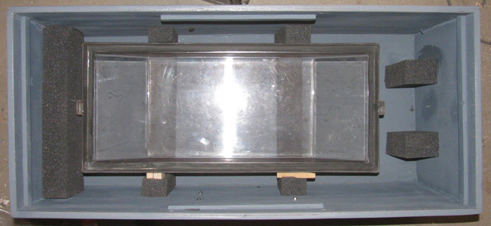
February 6th =================================================
Weather is nice this morning.
In the shop I went.
Starting with photo of Rescue Barge in the transportation box.
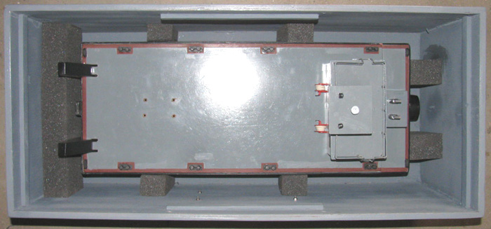
I have been soldering.
Power plug to the new speed controller.
Speed controller to the motor leads.
Make a bracket to hold the speed controller under the deck.
Reason is the speed controller is flat but it is longer than the space
under the deck house.
Find a couple of servo extension wires.
Plug everything in and see what works.
Rudder works and the correct directions.
Pusher Bars tilt servo works and in the correct directions.
Speed controller to motor works but is not in the correct directions.
I could reverse the system at the Tx but I will resolder 2 wires and
reverse the motor at the speed controller.
Done.
Speed controller works in correct directions.
Now I have an issue to over come.
The motor is way too fast.
The barge sitting on it's stand, the motor blew papers off the end
of work bench.
I tried to reset the Tx to 50% but I did not see or hear a difference.
Less than 50% I get several new sounds from the speed controller.
I need to do some research and find instructions for this speed controller
for setup.
This speed controller does not have a pause at neutral before changing
direction.
In fact it has a very sensitive neutral position.
If it is not right on the correct notch the motor runs.
There is no little past neutral at all.
Photo with deck in place.
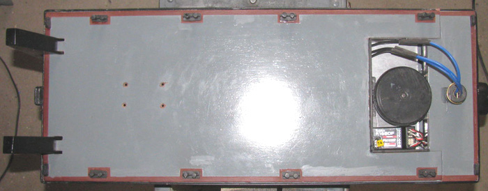
This photo is with the deck removed.
It is hard to believe after working on submarines for ever, that there
is so much empty room under the deck.
This all the equipment that goes in the hull.
The pusher bars linkage is mounted to the under side of the deck, including
the servo in the lower left of this photo.
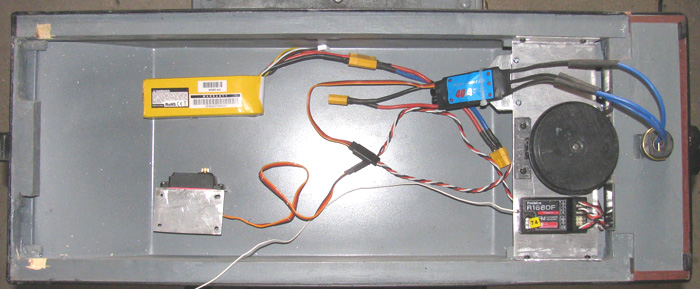
The hull will be filled with white foam.
I have made the piece and it fits tight.
I only need to cut out areas for the battery and servo.
The bow corners (left side of photo) are already cut out for the pusher
bar linkage.
Next, I plan to work on the steering cable.
Then I need to make something to hold the deck house on so it won't
fall off on it's own that works easily without tools.
Got an idea to try.
I am going to make 2 fire extinguishers that go on the deck house sides
and I can turn to release the latches.
Going to see what I can get done.
I have the rest of the day to work in the shop.
----------------------
I tried using the Tx computer to reduce the speed of the motor.
Got it down to 60% but another issue came up.
The motor gets hot running this slow.
So I think I will look for a slow rpm motor instead of trying to get
this one to run at half speed.
Moved on to making latches to keep the deck house on.
Making 2 fire extinguishers was not hard at all.
Soldered tubing inside one another until I got the outside and inside
where I wanted them.
The last piece on the inside is 1/16" rod that I bent and flattened
to make the handles.
The long rods will go through the deck house walls and turn a latch
rod.
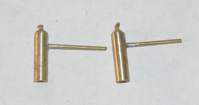
Placed them in several places to decide where I want them.
The sides of the deck house is where I wanted them and after tryuing
several places, they fit where I wanted them because the handles go under
the ladder rails.
Here the fire extinguisher is in the locked position.
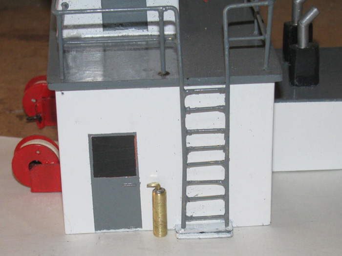
Here the fire extinguisher is in the unlocked position.
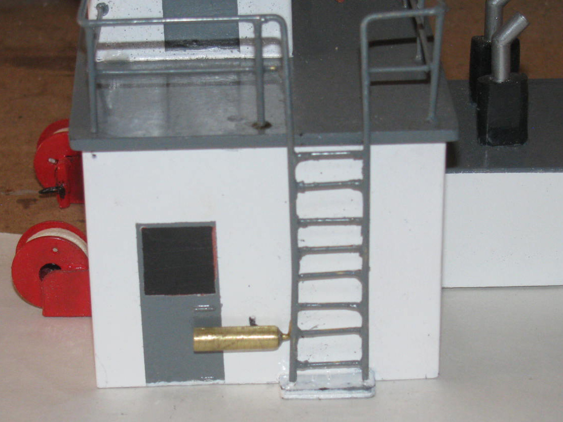
I will make the plastic locking blocks tomorrow or Monday.
February 7th =================================================
Fire extinguisher are now painted.
The plastic latch lugs installed.
This was not a big project.
The deck house sits on the deck by it's own weight.
The latches are to keep the deck house from coming up and off the deck.
There did not need to be any pressure on the lugs, just something to
keep the house from rising up and off the 3/8" deck house index rail.
I flattened some brass tubing and soldered to the 1/16" wheel collar.
Drilled 1/16" through the wheel collar and through the flattened tubing.
When soldering, I made sure I would be able to get to the set screw.
With the latch up like the far side, the Allen screw points down and
easy to get to.
The photo.
The far latch is in the release position.
The fire Extinguisher is almost horizontal.
The close latch is in the hold position and the fire extinguisher is
vertical.
In the opening on the deck, I put a 1/16" pin on each side to engage
the slot in the fire extinguisher latch arm.
I plan to put a small rubber washer between the wheel collar and the
deck house wall to provide friction so the latch does not move on it's
own.
Now to disassemble and sand and repaint the red. (something about the
red. it does not dry over night. it is still tacky)
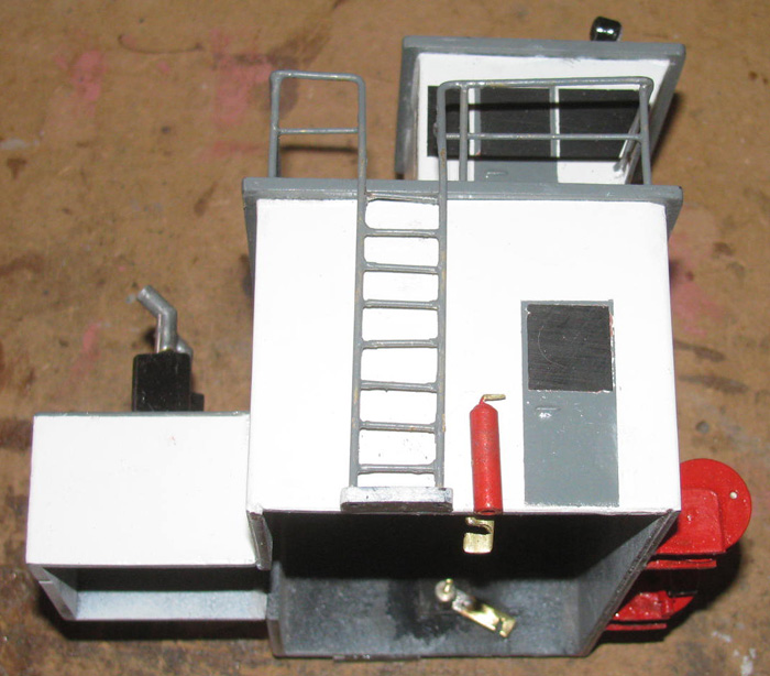
I have been thinking about the pod motor.
I can get it to run slower but at a certain point it starts cogging.
I remember this is why I took it out of the Skipjack.
The fix is to remove the motor and look for something else.
I have a couple of smaller motors I used for water pumps.
Those also were in the Skipjack for a few years.
The speed was easy to control and I could run the pump at very slow
rpm for trimming.
Until I put the piston it it. (love the pistons)
Anyway, I think I will put the smaller motor in the pod and see how
it works.
The barge does not need to go fast.
I just want forward and reverse control for maneuvering to a disabled
boat.
----------------------
This afternoon, I disassembled the motor pod.
I then disassembled the old water pump system from the Skipjack.
Using jumper wires, I connected the pump motor up tot he barge Rx and
battery.
It runs both forward and reverse with no problems.
I reduced the Tx to 25% on the throttle.
The motor does run at half speed with this setting.
The problem is this little motor runs so very fast.
I can throttle down and the motor will slow own but I can not get it
down far enough.
Looked over the motor and found the kv number.
It is far too high at 1850kv.
I want something around 300kv.
Another issues is this small motor get to a point when slowing down,
it just tops like it has a brake.
That is not a problem but interesting.
So, I think I need to research brushless 300kv motors some more.
I did a little more work on the deck house latches.
After 24 hours the red paint is still tacky and smears.
I was going to repaint them but I decided to take the paint off.
A little paint thinner and it all came off.
I think I am going to wire brush finish them and leave them brass colored.
I can always paint them later when I have a better red paint.
February 8th =================================================
I am on there looking at motors.
Problem is the ones that match the motors in my Skipjack and Akula
II are out of stock.
They have been out of stock for months.
Then a thought came to me.
I think I have a spare motor for the two boats sitting somewhere.
I planned to use it in the B-boat when I got it built.
But there has been no progress on the B-boat in a long time.
The wooden hull plug set long enough that it cracked beyond repair
and will have to be remade.
Think, "What are the chances I will get back to it?" Not very good.
So, I think I will look through the parts boxes and see if I can find
that motor.
If I do, I will install it in the Rescue Barge motor pod.
Every thing in the barge is compatible with that motor.
If I find that motor it is a 15 to 20 minute install.
And I got notice that the 2 new control arms for the high torque servo
are at the post office ready for pickup.
3 days it took for delivery.
I will be in town later this morning.
The steering is still an issue.
The servo I am using does not have enough torque because I am trying
to make this 60 degree servo move 180 degree rudder post.
I looked up the specs on the high torque servo I have.
It is rated at 20kg.
Just about enough to fold my barge in half.
But is is only 60 degrees.
BUT right next to this servo on the sellers web site is a 25kg servo
that is. . . . a 180 degree servo.
I have a lot of time in the current servo trying to make it work.
$15 for this high torque 180 degree servo is not too much to pay.
I will be ordering after finding out it would be here in 2 to 3 weeks.
I am not in a hurry.
Can't go any where any way.
So the search of parts boxes will begin. . . soon.
---------------------
Another project that is not critical at all.
I may make some detail parts.
Say, three 55 gallon oil drums.
Some coiled rope to put by two or three bollards.
Maybe a stack of lumber like rail road ties for blocking.
Some life rings for tossing to man overboard to mount around the barge.
These parts can be made any time after the Rescue Barge is operational.
I have 3 small boxes in the house where new un used parts are kept.
Went through those boxes.
I found 3 empty motor boxes.
This is not good.
Okay. . . . 1 motor went int he Skipjack. After thinking about it,
the other motor went in the Gato.
How did that happen.
Well the 3rdf motor was going to go in the B-boat that has not been
built because the hull plug failed.
Then I ended up with a Gato boat kit.
It sat on my back porch for a couple of years because I never planned
to build it.
But then I was between builds and decided to look in the box.
I should have never done that.
Found my self dry fitting parts together.
Then came the glue.
Then my work bench was covered with Gato parts being assembled.
While looking for the extra motor this morning and finding 2 empty boxes,
I got out and opened my build files.
Looking through photos, I quickly found a photo of the motor sitting
on the Gato equipment try.
Yep, Akula II, Skipjack and Gato. . . that is 3 motors.
So, I am still looking for a motor on the net.
-------------------------
I ordered the 180 degree high torque servo to use on the steering.
I need the 180 degrees more than the torque but for the price, torque
is good as well.
Before ordering, I went out to the shop and tested the 20kg servo I
have for the pusher bars.
It does not have more than 80 to 90 degrees of travel using the Tx
to get 140% on the servo.
I found a motor of the same physical size so it will fit in the pod.
It is less than half the rpm of the motor I have been trying to get
to work, which is good.
750kv. (I would have liked to found a 300kv)
I ordered it and will see how it preforms in this application.
But for now, I have some waiting time.
I will finish up a few little things on the barge and maybe get back
to the Gato cylinder which I put aside to do the barge.
If I remember correctly, I only need to drill a hole shallow in the
end cap to hold the safety cable.
Then reassemble and test everything to figure out where I left off.
I think the boat was very close to water testing again.
Maybe I can get the Gato and the barge ready to test at the same time
so I only have to fill the test tank once.
-----------------------
And there is more
I received the high torque servo arm. (it is made of titanium)
I set up the Rx and 2 servos.
Turned it all on and ran test to see where the limits where set.
I reset the pusher bar servo to 25 degree both ways.
Then I looked over the connection push control rod.
I did not like it.
It is too short and cause angles that might end up binding when a load
is on the pusher bar lift arms.
Easy enough to fix.
Make another longer push control rod.
Made it 3" longer.
This appears to be much better and I have room to go maybe 12" long
if needed.
Drilled the ends for the pins and line everything up.
Measured for the new servo base plate bolts holes.
Drilled it.
Counter sunk the holes.
Applied CA glue to harden up the wood.
Will recut the counter sunk holes tomorrow.
Filled the old holes in and will sand then flat.
Tomorrow I should have the pusher bar controls completely installed
and test and adjust the throw of the servo arm.
Once I recut the counter sunk holes, I can drill and counter sink the
holes for the 8 deck mounting screws.
I can also cut the flotation foam for the servo.
I would cut for the battery but I want to wait until the barge is in
the water to put the battery so the boat floats level in both axis. (fore
and aft / bow to stern)
February 9th =================================================
So far I have recut the pusher bar servo holes.
The CA glue makes the wood very hard and I had to be careful the drill
bit did not bit and pull through.
Just be safe, I turned the drill bit with my fingers.
Now I have sore fingers.
Anyway m the servo bracket with the servo is mounted to the underside
of the deck.
I removed all the pusher bar linkage.
Reason is I am going to repaint the upper deck.
Why, during all this messing with the under deck linkage stuff, I knocked
off 2 bollards.
I was not sure about just gluing them straight to the deck in the first
place.
I drilled a hole in to the underside of every bollard.
I cut brass 1/16" pins and CA glued them in.
After the deck is repainted, I will mark and drill through the deck
for the pins.
This should stop the bollards from being knocked off when tapped from
the side.
I lined up the fire extinguisher latches to the deck house pins.
A close look showed it was not the latches of the pins, the fire extinguishers
where 1/32" to long on the bottom and where touching the deck raising up
the deck house.
A couple touched with the grinding wheel and all is good.
Cleaned the deck house for some touch up painted behind the fire extinguishers.
Sanded the deck for repainting.
Repainted the outside edge where the red primer outlines the deck.
Letting it dry before taping to paint the main part of the deck.
It is cold and sprinkling here so it may not get painted until Friday.
Next two days I will be at the VA having scan test done.
Nothing serious.
Just trying to find what is causing a small issue that will not go
away.
I found an old plastic disk I turns some time ago and did not use.
I chucked it up in the drill press and I turned t down to a new smaller
diameter for the new servo coming.
I was going to make a plastic part to hold the heavy control arm.
Well, that is not going to work because the new disk is smaller in
diameter.
*** But while typing this, I thought of a way to make it work.
Make a larger two layer disk that I can cut the arm in to.
Then bond the smaller disk on top of it.
I have room and the larger disk will help keep the control line not
fall off the bottom of the pulley disk.
This is something I can turn in a few minutes then take my time hand
cutting in the servo ark profile with a drill, knife and file.
Then I can drill a hole through it all to match up with the threaded
hole in the control arm.
I got a plan, I can do while it's cold and possible rain.
------------------
With the idea on how to make the pulley control arm work, out to the
shop I went.
I cut and glues 4 layers of sheet plastic together.
Clamped them in the table vise.
While the glue cured, I decided to fit the 8 bollards on the deck.
I needed to measure the 2 pins on the bottom of each bollard and drill
the deck to match.
I slowly worked my way around the deck fitting 1 at a time.
This took maybe 30 minutes.
All the bollards are fitted and will be removed when I paint the deck.
Leaving them in will hopefully keep me from mixing them up.
The pins are not in the same place on each bollard.
Okay, back to the pulley parts.
I need to drill a 1/4" hole in the center so I can turn the part in
to a disk using the drill press.
This takes about 5 minutes because I rough the shape in with the Dremel
and cutting wheel.
After making the disk the correct size for the finish part.
I took it in to the shop and traced the outline of the servo arm on
to the disk.
I started to cut the hole for the arm with the cutting wheel then stopped.
Measured the control arm and found that the end is a circle.
Out to the tool shed and drilled a 9/16" hole using the 1/4" hole as
a guide.
I had the arm with me so I test fit it.
It was very tight but a couple of hits with a round file would clean
it up.
Back to the shop.
Cleaned the hole of burrs with an Exacto knife.
The arm fits tight but with a little pressure it pushes right in.
Also when I tighten up the arm end with the 2 small clamping bolts,
the part should drop right in.
With the arm end pressed in to the hole, I traced the am end on to the
disk.
With the Dremel cutoff wheel I cut the slot for the arm.
This all took about 15 minutes.
On the left is the original pulley that would make the 60 degree servo
move the rudder 180+ degrees.
On the right is the new pulley that is slight larger that the rudder
pulley. (this gives me room to trim if needed)
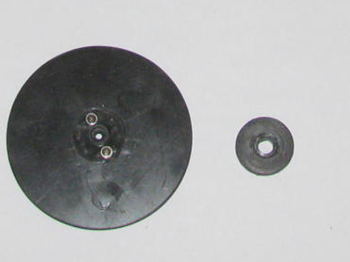
Here are the new pulley, servo arm and servo arm retainingg ring.
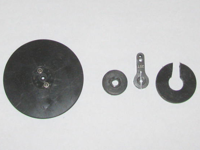
Arm pushed it to the retaining ring.
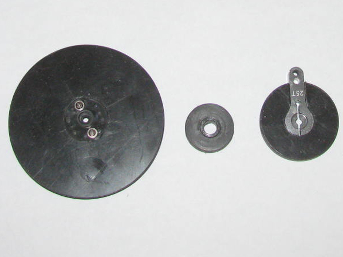
New pulley assembly without the top disk to stop the cable from running
off the top.
The servo shaft is threaded.
My local hardware store had a metric stainless bolt section.
I should be able to find a bolt to fit and hold the pulley on the shaft.
Though the arm clamp is suppose to do that as well.
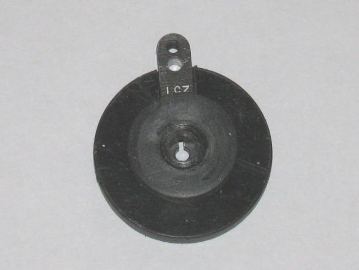
February 10th =================================================
Back from the VA.
The 2 hours in the scan machine with good results.
Nothing found at all. (all good)
20 minutes talking with the neck surgeon. (all good)
Back at home.
A little lunch and out to the shop.
The pusher bars servo was installed in a new location because of lengthening
the control arm.
I had 4 old holes to fill and sand.
I also filled over the bolts through the deck so now the deck is flat
with no bolts showing.
Yes, I put CA on the holes in the wood then I put CA on the bolts to
hold them from turning.
The filler was put on yesterday so I could sand first thing when I got
home.
But a second coat was needed for 2 bolts.
Filled the 2 spots.
I cut 8 plastic sheet plastic squares.
I glued the pieces in pairs.
In to the table vise.
I am going to see if I can make 4 life rings.
Originally I wanted 2 but found a place for 2 more if they come out
looking okay.
Back to the deck I had set out in the sun.
Brought it in to the shop
Sand the 2 filled spots.
Taped off the edges and the 8 locations for the bollards.
Sprayed a very light coat of gray paint on the filled spots and the
over sprayed primed edges.
Waited 30 minutes and put a good coat of gray on the deck.
I even repainted the stern block on the hull after taping the edges
and chocks.
I am going to let the paint dry over night before pulling the tape.
Just in case I need another coat of paint.
I will work on the life rings tomorrow afternoon when I get back from
town.
For a day I expected to be gone all day, I got a lot done.
=====================
It was not as late as I thought.
Okay, I had to go look at the paint.
Looks good.
Pulled the tape.
I got a straight edge which for me is a miracle.
Took the 4 plastic I glued together pieces out of the vise.
Drill a center hole in each one.
Out to the drill press to turn them in to disks.
Brought them in to the shop a couple of times to see how they looks.
There is no scale to this barge.
If it looks good, that is the size the parts will be.
Looks about 3/4" in diameter.
While I still have a small hole in the center.
I turned each disk and rounded the outer edge.
Next I will have to drill the small hole larger to get rid of some material.
Then I have to round off the inside edge. (by hand with a file or a
length of sand paper I can draw back and forth)
Now I am done for today!
February 11th =================================================
In the shop for a few minutes.
I needed to correct the bollard deck outlines.
Decided to get rid of them because they never looked right to me.
Besides they are hard to line up with the bollards because the bollard
base plates are not all the same shape.
So I just painted then out.
On to the 4 life rings.
Drilled the center hole larger.Knifed and files the edges round.
Sanded smooth outsides.
Mixed up some yellow and red to get a dark orange color.
Got the first coat of paint on one side of the rings.
Deck has dried enough to bring inside and pulled the tape.
Set the deck on the hull to dry the rest of the way.
I filed on the key hole slot in the steering pulley.
The key hole was good but the servo arm has rounded corners that made
the fit too tight.
A couple of passes with the file and no more problems.
I centered the pulley center section on to the bottom section using
a drill bit.
Applied the cement and got it in to the vise.
The rudder post pulley. . . I needed to fit the over cut for the steering
cable end.
Not a problem.
Find a scrap piece of plastic and shape it to fit the pulley top edge
shoulder.
Applied cement and clamped.
Tomorrow I should be able to get another coat or two in the life rings.
I should be able to install the 8 bollards back on the deck.
February 12th =================================================
I only had a short time in the shop.
Do as much as I can while there.
Finish painting the life rings.
They need to dry completely before I can put the rope around the rings
and make the mounting brackets.
I might just paint the brackets on the rings.
Put the pusher bar linkage back on the under side of the deck.
I started cutting flotation foam to accept the servo and push rods.
This turned in to a mess.
Foam every where.
I thought about this and decided that I will cut the foam in to blocks
as needed instead of trying to make it 1 big block of foam with cutouts
for the linkage and servo.
If I cut blocks, I can fit them around the equipment.
That is the current plan.
The 8 bollards have been glued to the deck.
With the pins through the deck, the bollards should not fall off from
a simple bump.
February 13th =================================================
Working on the life rings.
I used a very good white medical tape to make strips to put around
the life rings to look like the canvas pieces where the hand rope attaches.
Sort of looks like this image.

Got them taped and began to clear coat them.
Well, I have said it many times, "I hate painting".
The clear coat came out of the can light gray.
I stopped.
I got the paint thinner out and a rag.
I cleaned of the gray.
I got most of the gray off and the orange seems to stay in place.
I tossed the clear coat "GRAY" in the trash.
I have a gloss clear coat I will try. . . on a test piece first.
I did not want the gloss but I can wire brush the shine off the gloss.
Letting the gloss dry, I am looking for a suitable thread to put around
the rings.
I have a dark heavy thread for leather and a white standard thread.
The standard thread looks too thin.
I think I will stop for today.
The wind at 30 to 50 mph is putting too much dust in the air.
Even with the shop door closed I can see the dust moving around in
the air.
Went and looked at the life rings.
What a mess!
The clear coat made the orange soft and it bleed through the white
tape.
None of it is drying right.
I am going to bring the rings in the house where it is warm. (too cold
outside)
I will let them dry for a couple of days then sand them down and start
over.
I will clear a spot off the kitchen table so I can do it where it is
warm and maybe the paint will cure.
I think I can save the rings at least.
February 14th =================================================
I brought the life rings in the house yesterday so they would stay warm
and dry.
This morning the paint is dry and hard.
The warm house did the trick.
In the shop I did a little sanding to test the paint hardness all the
way down to the black plastic.
This went well and I sanded all 4 rings.
I took a very small piano wire and cut it to fit the Dremel.
I drilled a small hole in the rings.
What I wanted was the wire to hold the ring so I could paint all of
the rings and then stick the wire end in to a foam block to hold it.
I cut 4 pieces of piano wire and processed to drill in to the rings.
On the first 1, I pulled the wire out and put another wire in the hole.
This did not go well.
The new wire did not get tight in the hole and ring would fall off.
Looking at in the Dremel there was melted plastic on the end of the
wire.
Okay, I took that wire and redrilled the hole and stopped when I got
the wire in far enough without going through.
I unchucked the wire and it was stuck.
The melted plastic seems to be holding on. Quite well.
I did the other 3 rings.
Mixed the yellow and red to get the orange I want and thinned it down
with a few drops of thinner.
Painted the ring and it covered well.
Stuck it on the foam block.
Did the other 3 rings.
Closed up the paint bottles and cleaned the brush.
In to the house with the foam block. (In my kitchen it is alomst 70F.
Much better than the 43F in the shop.
I connected up the Rx, Speed controller and pusher bars servo.
Found center of travel.
Disconnected the linkage arm.
Now I can adjust the rotation from the 35% it is now to 100% to get
to the 2 servo arm bolts to tighten them.
Turns out I do not have the right Allen wrench.
I have bigger and smaller.
Guess when the other servo gets here, I will take the arm and bolts
to the hardware store to buy a couple the right size.
Might as well adjust the servo for travel.
35% up and 40% down seems to just touch the deck with out binding.
This is where I will start once the deck is bolted down. (after the
new motor and servo are installed)
I am at a point I am just making work.
Next, I will measure and drill for the deck mounting bolts.
The layout of equipment is complete so I know where to put wooded mounting
blocks.
But I thing the wooden frame I put in way back at the beginning may
be in the correct position for this.
So I am done for today but I have to go outside and see what wind damage
the house took yesterday.
Going to the shop I can see aluminum siding over 2 windows is either
bent or missing.
There are roof shingles in the back yard, most likely from the out
buildings.
The house is sheet aluminum so it should be okay.
February 15th =================================================
Earlier today, I was headed out to the shop.
I could hear the wind beating on the house and roof.
I opened the back door.
Well, that is not quite correct.
I started to open the back door when the door pushed me back in to
the house.
Now I have lived in the desert for a long time.
I know what to expect and have survived the past.
I opened the front door which opens in, and looked out side to see what
was going on.
Visibility was not good.
I can see the house accross the road but that is only 500' away.
I looked to the north which usually I can see about 40 miles.
Today, 1/4 to 1/2 miles it all I get.
So, there will be no painting or gluing today.
Well I could make the deck non skid by just spraying on a clear coat
and letting the dust in the air take care of it.
So today I will try to stay warm.
February 16th =================================================
It is still very windy.
But I have to do something or the barge build stops.
Took the life rings out to the shop to put the ropes around the rings.
Working on 2 at a time, things went well for about 10 minutes.
Then the ropes did not look right.
They actually look like crap.
Okay, I came in the house and looked at more photos of barges and tugs.
I was surprised at how many life rings did not have the hand rope and
only the toss rope.
If I had seem this easler, I would be done now.
Pulled the ropes of and filed and sanded the glue off.
This caused more painting.
Got that done.
I got real good at mixing yellow and red to get the orange.
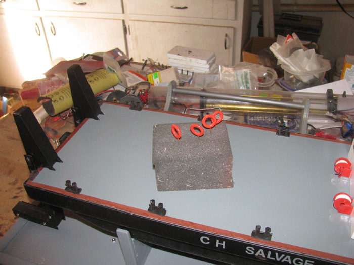
I moved on to the push bars to make sure the mounting bolt holes lined
up at 3" to 7" depth.
All went well until I got to the last hole and got it drill including
1/8" in to my finger which I was backing the second aluminum plate.
Wasn't a problem when there was longer plate.
Did not think it through on the last hole.
Oh well. I heal quickly.
I though I would show what I have been trying to accomplish with the
push bars.
In the down position I should be able to move up against a boat.
By knowing the boat hull diameter I can set the push bars depth to
go under the hull at decks awash.
Here is my George Washington sitting on the push bras. (3" diameter
hull)
After pushing up against the hull, I can move the push bars to the tilt
position.
Here the George Washington is in sitting on the push bars.
The brass brass holding the push bars up are there because the servo
is not connected at this time.
It is a very high torque servo and I can not move it with out power.
(20kg servo)
The push bars should lift the hull just a little to make it heavy on
the push bars low.
The channel this is on is a knob so I can lift just what I need and
not too much.
I hope this keeps the hull from going down and rolling under the barge
when pushing.
February 17th =================================================
It is still very windy.
But I turned on the heat in the shop.
I figured I would be out there about20 minutes.
That did not happen.
I was trying to tape the life rings to paint the white stripes.
I could not get the tape to run where I wanted it.
The curve of the rings kept pulling the tape off line.
I tried painting on stripe I did get taped.
It failed and I cleaned the white off.
Off the options I thought of, hand paint with a brush seems the least
stressful.
Found my smallest thinnest brush.
Put a couple more drops of white on my mixing board. (plastic)
Added a couple of drops of thinner.
Made a couple test passes on black plastic so I could see what was happening.
Turns out there was not going to be any brushing at all.
Just line the side of the brush where I wanted paint and just touch
the part.
It is not perfect by any means but I am not going to work on this painting
any more.
I did all 4 rings and they are what they are.
I do not like painting and working with small parts is not a problem
but painting.
These rings are less than 3/4" at their widest.
Set these aside and I decided to drill holes through the deck for the
brass screws that will hold the deck on.
I needed 2 near the front to hold the deck down when the pusher bars
push and lift the sub or boat.
2 at the back and then instead of 2 down the sides, I put 1 center
of the other 2.
I counter sunk the holes for the screw heads and then I applied thin
CA to the bare wood to give it strength.
I will re-cut the counter sink holes after the CA cures to get the
right depth.
February 18th =================================================
Sun is out thought it's 40F.
It is windy but not so much.
I can count the blades on the roof vent spinning.
Okay, in to the shop and turn on the heater.
I plan to paint but while it warms up, I will finish the deck holes
by hand turning the drill bit to clean up the CA I put on the bare wood.
This takes a few minutes.
Look at the life rings to see if I need to do more.
Nope, they are going on the barge as is.
First 2 rings are going on the pusher bars.
The pusher bars are off the barge deck so I can lay the pusher bars
on their sides and set the rings down flat.
Moved them around until I think they look right.
Get my Exacto knife to get silicone glue out of the tube and put the
glue on the life rings in four spots.
Using a 1/4" block to get the height right, I carefully set the ring
on the side of the pusher bar.
I was originally going to put them on the outside of the pusher bars
but when I looked at it, there was not room.
I mean if the barge was working a man could not work on the outside
of the pusher bar with the ring in the way.
So, I looked at them on the inside and that is where they are now.
Next to the deck house.
Again I was going to place the rings on the sides of the deck house
railing.
And again it does not look right.
Tried a couple other places and the one that looks the most correct
is on the back hand railing.
A little silicone glue and there they are.
After the railing ones cure, I think I will use some thread and tie
them to the railing to make them more secure.
From the stern.
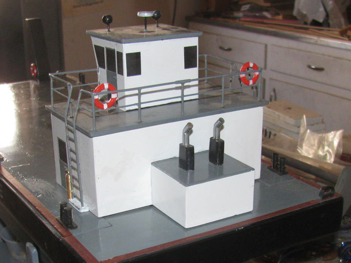
From the bow.
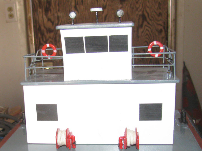
I might try coiling some thread to look like rope but so far I have
not had any luck with my big fingers.
I have reached the point that I am waiting for the new main motor and
rudder servo.
Other than making little detail parts to put on the deck, I think I
am done.
A tool box at the front of the deck house might look good.
Couple 3 oil drums, maybe.
Well, until water trials and then I can paint the waterline.
I noticed there is black paint splatter on the deck house in places.
They did not wipe off.
To fix it, I would have to repaint the deck house completely.
I do not think that is going to happen.
----------
This afternoon I was back in the shop.
Thought I would connect the pusher bar linkage.
Done.
I think I will get stainless steel bolts to replace the Allen screws.
The socket in the Allen screws are not strong enough to put and torque
on the screw.
I will pick some up tomorrow in town.
While counting the needed bolts, I checked the rudder system for a bigger
rudder post pulley.
This is not going to happen unless I cut a opening in the engine cover
to let the pulley stick out of the cover.
This is something I should have done a weeks ago.
With the motor pod out of the boat, I can set the rudder pulley on
the deck and then put the deck house on.
Well, this is not good.
I could not set the deck hose on dropping it straight down.
Okay, off with the deck house.
Sit the rudder pulley on the deck back way from the rudder post hole.
Slide the deck house of from the rear until it drops down on the deck
flang.
Lift the deck house straight up carefully.
Look down the through the pulley and see where it sits over the rudder
post hole.
This is not good.
The pulley is pushed past the hole by 1/8".
This means when the deck house is in place, it binds against the pulley.
Did not notice because I did not test the rudder servo and rudder post
with the deck house on the barge.
Okay. I got my Dremel 1/2" sanding drum and sanded a notch in the deck
house engine cover back wall.
I also took the pulley out to the tool shed and chucked it up in the
drill press.
I cut a little of the pulley flanges.
In less than 10 minutes, the pulley did not move when I slide the deck
house in to place.
I now have clearance on the rudder post pulley and engine cover.
February 19th =================================================
Before going to town for bolts, I thought I would make up 3 tow lines.
Using braided nylon and trying to dye it dark brown.
Using tea bag.
Checked the thread in the servo to get a couple of bolts to hold the
horns on.
Checked shipping on the new rudder servo and motor.
Not ordered from same company.
Servo will be here the first week of March. (March 6 or so)
The motor is on a much slower boat.
Expected delivery, April 21.
So after making the tow ropes, I thin I will clean off the work bench
and get the Gato back on it.
Seems I left it with needing a shallow hole in the end cap for a safety
cable pin.
Then it is a matter of cleaning all the dust of all the parts and reassembling
the cylinder and get it the hull for water testing.
Might take a couple of days to sort out all the parts as the got mixed
in with the barge build stuff.
I do have a working plan.
I take photos of every step I do so I should be able to match up the
parts in the photos to reassemble.
-----------------------------
Back from town with a lot of stainless steel bolts to replace all the
Allen screws.
4-40 by 1/4".
Sat down on my wooden milk crate and removed all the Allen screws and
putting in bolts with Phillips head for screw driver.
Much better tightening.
There are 2 bolts that may need a flat spot put on the shaft to keep
them from slipping.
Won't know until I can put the boat in the water and try to catch a
sub.
Or course as much as I hope to not have to catch stranded submarines,
this slipping may not ever become a problem.
February 20th =================================================
More progress.
Found a small switch which can handle the load.
Soldered the switch in the power wire and then put on a new plug.
Drilled a hole in the electronics tray and mounted the switch.
I plugged in 2 test servos and the speed controller.
Yes, I checked the switch for which way is on/off.
Turned on the Tx and then the Rx.
Tested the 3 channels used.
All is good.
I mounted the Rx using a couple of drops of silicone.
I like silicone because I can remove it, cleaning it off and reinstall
as needed.
I made a couple of labels to tape on the electronics tray.
OFF/ON switch and I labeled the Rx because I keep having to look up
the channels.
1. Rudder
3. Throttle
8. Pusher bars tilt.
Using packing tape I put the labels on the tray.
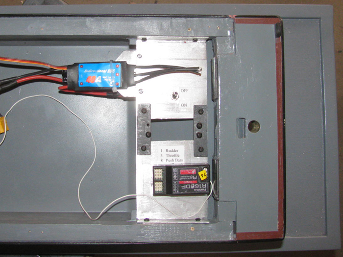
Set the deck in place.
Now waiting for the motor and rudder servo.
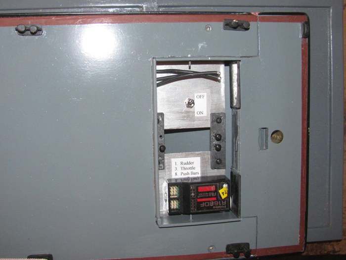
I made up the 3 tow ropes.
I dyed them brown because white did not have the look.
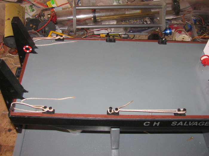
View front the bow.
(should have taken the parts of the lid)
In this photo, the holes for the lower pusher bars are visible.
I can set the depth from 3" to 7" depending on the boat's hull to be
retrieved.
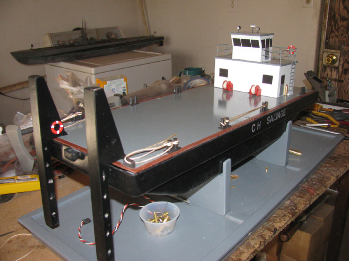
The 2 remaining parts needed will not arrive until April.
I think the barge will be going in to the transportation box to protect
it and I can have my work bench back.
I need to cut 2 pieces of gray foam once the barge is in the box to
hold the barge down for travel.
February 21st =================================================
I had about 20 minutes I could work in the shop.
I put it to good use.
I needed to cut inlet in the flotation foam for the servo, servo linkage
and the battery.
I had already cut out for the speed controller. and the steering servo.
I needed to find where to put the battery which would be sitting on
the hull bottom to get the weight low in the hull.
I put the deck and deck house on the hull with the battery out.
I put the pod parts and old motor on the steer for the weight.
I put the battery 90 degrees from the photo.
I move the battery all the way forward to the bend for the rise at
the bow. (1/4" back from the end of the foam.
I placed the battery so one edge was on the hull center line on the
opposite side of the pusher bar servo.
The battery is on top of the deck at this point.
I put a brass 1/2" round tube under the hull, side to side, and moved
it until I had the hull level.
I measured to see how close to center of the hull I was.
Moved the battery back about 3/8" and the hull leveled up on the brass
tube.
Marked the foam with a pencil.
Removed the deck house, deck and foam.
I cut out a place in the foam for the battery and then a slot for the
wires.
I cut the foam front to back using the side of the battery to make
my cut mark.
The foam is now in two pieces making it easier to install and remove.
The distance from the battery power plug is now close enough to remove
the extension wires and plugs.
Battery now plugs directly to the speed controller.
The battery is in the cut out tight enough that the battery will not
slide around.
I have room in the foam to cut if I have to move the battery after
water trimming.
Or I may add weight if the hull sits too high on the water.
The Rx antenna will lay on top of the foam under the deck.
There is nothing there in the way.
That's it for today.
February 22nd =================================================
I woke up at 4am.
Could not sleep.
So, I finished up my taxes ready for delivery to the accountant.
Later morning on way to accountant to drop off my 3 page summary sheets
and other personal id papers.
DONE.
Finally got in to the shop later this afternoon. 4:300pm.
Looking at the foam flotation blocks I realized I could glue them back
together having cut all the inlets for the battery, servos and electronics
tray.
Okay, I smeared clear silicone on the sides of the blocks that would
mate up.
Set them on the work bench and made them level.
Couple of wooden blocks and clamps and the blocks are now glued together
and will be one tomorrow.
I had to cut a couple of notches bigger in the hull deck framing.
The pusher bars linkage fit too tight and the hinge rids with wheel
collars hit.
Actually the new longer stainless bolts where longer and hit the bottom
of the cut out.
Touched up the paint.
I have plenty of room now for the bolts no matter which way they are
turned.
Yesterday, I was testing the electronics.
Learned that when adjusting the servos, I need to reduce the movement
to about 10% before starting.
If the deck had been screwed down when I turned on the system, the
high torque servo would have broke things.
When the servo jumped to the Tx control setting it was set to full
up.
It should have been set to center to stop what happened.
The servo jumped and the deck bent up about 1/4" at the bow.
The servo is a 20kg torque servo.
I can see this servo should have no problem when lifting stranded boats
like a fork lift.
I opened the servo end program and set the servo so it would not go
past full up and full down limits of the pusher bars deck stops.
What an eye opener this was..
Now thinking to the rudder servo that is coming.
It is a 25kg servo with 180 degree movement.
I will make sure the Tx controls is centered before turning on the
system.
I would hate to see the rudder post pulled out of the wooden block
(1.25" thick)
It might break the stern block from the hull.
Tomorrow, I plan to clean the barge up and find the few parts needed
for the steering and put them all in the transportation box for safe keeping.
Until the parts show up in April.
I looked at the Gato cylinder and parts.
They all have about a foot of dust on them so cleaning will be necessary
before I can go back to work on the Gato.
The Gato hull is sitting off one end of the work bench.
There is so much dust on the deck, I can not see the deck slats detail.
I will need to be careful so as to not break anything off the deck
I should have put the Gato in it's transportation box before starting
the barge.
Now I know.
February 23rd =================================================
In the shop.
I put the deck on the hull and screwed it down.
Had not done that yet.
Needed to have the screws cut the threads in the wood frame.
Put the deck house on the deck.
Gathered up all the motor pod parts and set them on the transportation
box lid under the hull.
Propeller shaft, propeller, 2 wheel collars with prongs to engage the
propeller, 3 screws to hold the shroud on, the shroud and the pod front
and back pieces.
The 2 pulleys for the steering.
That is all there is to finish the barge.
Moved the barge on the lid over to the box and set it down.
The barge is off the bench.
===============================
Turned on the air compressor and set it to 40 pounds.
I didn't want to blow parts of the deck of the Gato as I cleaned the
dust off.
40 pounds was a good guess.
The Gato is now dust free.
Used the air to blow off half the work bench where the boat will sits.
Mostly sanding and grinding dust.
Found the Gato plastic stand.
The Gato is now on the work bench ready to continue.
Next will be cleaning the cylinder, two electronic trays and all the
parts that go on the trays.
Going to go through it like I was getting it ready to go to the lake.
Clean everything and grease the parts that need clean grease.
Once I get the parts clean, I can lay then out on the bench to see if
I have all the needed parts.
I had this boat complete assembled and working.
So all the parts should be there.
I took it apart because I needed to make the ballast tank larger by
3/4" to get waterline.
And where I stopped was installing the new safety cables to hold the
end caps on the cylinder.
The original holes worked on one able but not the other.
I filled the hole so I could re-drill the location.
That is where the barge interupted progress.
This afternoon, my plan is to sweep the floor and go through the pile
looking for runaway screws, Allen screws, bolts and other parts that fell
from the table.
Now these parts are not that important.
Missing parts where replaced so I could continue to build.
So anything found will be spares now.
So I am still working a little each day on something in the shop.
February 24th =================================================
This is not good.
I resumed work on the Gato this morning.
After reaching a stopping point for today, I came in here to post the
progress.
After typing up what was done, I realized, that my build thread is
not here on Sub Committee.
It was over on Sub Pirates and is now gone.
The good news is, I have all my build info on my personal web site pages.
So it is not lost to anyone who wants to see it.
I do not plan to try to put it all here.
It is just too much to try to redone again.
But I can make it easy.
Here is the original build web page address.
http://www.cliffhangershideout.com/Gato/Gato-log-1.html
.
I will get back to the barge after the 2 parts show up.
February 25th =================================================
I have been gone today but did stop at the post office on the way home.
Seems like my birthday.
I got a letter from my home owners insurance saying they made a calculation
error and I will be getting a refund in 2 weeks.
I got a second letter from my auto insurance which said do to less
driving because of the virus, I will be getting 10% refund. This is the
third such refund in 8 months.
Even more.
There were 2 small plastic packages.
I opened the first one and there is the new motor that is suppose to
be delivered in April.
Opened the second package and there is the rudder servo.
Took it out to the shop to test it.
This is where things when wrong.
This servo is a high torque 180 degree servo but the package has printed
on the box 60 degree and 60 degree. 120 degree servo.
Tested it any way to make sure.
Sure enough, it is the wrong servo. (arriving 2 weeks early, something
had to go wrong)
I sat down and typed up a message to the seller.
I thought I would make it easier on the seller by keeping the servo
(because return shipping is more than the servo) and I would pay for another
180 degree servo.
Now I wait to see the response.
Anyway, I can work on mounting the new motor in the pod.
It is a little smaller that the one I had in there so there should
be more clearance.
I will continue working on the Gato.
Building submarines is so much fun.<g>
February 26th =================================================
Before leaving for a few hours, I went out to the shop and unboxed the
new motor.
This motor should be half the RPM or even less.
I needed to slow the motor down by a lot so I hope this is going to
work.
This motor is the same diameter but it is 3/8" longer.
Good thing I left room in the pod. (the pod is long to make it look
good)
The original motor mount bracket does not have the mounting holes in
the same place.
So I removed the old one and trimmed the provided mount to fit in the
pod.
I even removed more plastic from inside the pod for better motor clearance.
I need to cut the wires and lengthen them to get through the rudder
post.
After than I can put the motor in the pod mounted to it's bracket.
Shim the motor for clearance and then epoxy the bracket in to the pod.
------------------------
I have been emailing the seller of the servo.
Interesting that they say they do not have a record of the sale.
Too bad, I sent copies of all orders and confirmations of orders and
tracking info.
I have not heard back.
While sending the e-mail stuff, I did a search for the servo to see
if I had the info correct from other sellers.
Then on my screen, a pop up.
It was from the seller I bought the replacement metal arm for high
torque servo I have.
It was not something I wanted but I used their search and looked for
the servo I had ordered else where.
Wow! There was a list of several high torque servos.
The one I wanted info on was there but there was another 20KG servo
that only came in 180 degree or 270 degree.
The difference was the shipping.
The first one was free and this one was $2.+.
The big difference was the original was shipped from China.
The second one was also from china but in a warehouse in southern California.
I remember the arm came in 3 or 4 days. Not 2 months.
Okay, I will still try to deal with the original seller but I ordered
from this local warehouse seller.
Maybe be the servo will be here next week.
Got to go for now but I think I will get the motor in the pod this afternoon.
Remember the motor got here 3 weeks early so I am still ahead of schedule.
<G>
My time away was not nearly as long as I thought it would be.
-----------------
Motor issue to be solved.
The shaft is bigger in diameter.
So my connector will not work.
This is the original connector.
Assembled.
The brass tube slips over both the motor shaft and the propeller shaft
and the set screw goes through holes in the tube in to the shafts.
The new motor shaft is the same size as the brass tube so it will not
go into the tube.
I do not have a lathe or access to one and I do not think my poor man's
drill press lathe will do the job of turning down the motor shaft.
But wait, I have an idea that I need to take out to the shop and see
if I can make it work.
A standard wheel collar fits over the motor shaft.
I need to find a wheel collar that fits the propeller shaft.
Then See if I have a brass tube that both wheel collars will fit in
to.
I can drill holes in the tube for the set screws.
Solder the wheel collars in the tube and install the set screws through
the holes.
If I have a brass tube that is slightly smaller, I can run a tapered
rod through it and enlarge the tube enough to press the wheel collars in.
The wheel collars and tube will be pre tinned with solder and the parts
will needed to be heated before pressing together.
I have a plan, now to see if I can make it happen.
This all depends on if the large tubing will fit in the space in the
tail come.
I do think I have room to make the recess in the tail cone large if
needed.
Find my camera and out to the shop.
This needed to be photographed just in case it works everyone can see
it happen.
--------------------
Looking at the assembled photo, I think I can use the parts.
Cut the inside brass tube in between the 2 collars.
Use the propeller side because it actually is the stand off bearing
to the tail cone.
I know the motor side collar fits over the new motor shaft with the
brass tube inside removed.
Just need the outside tube.
A more improved plan.
--------------------------------
I do not have the correct brass tubing to go over the wheel collars.
(I will get some next time I am in the big city)
I have drilled and aligned them up using stainless rod and brass tube
shim.
I soldered the 2 wheel collars together.
Here they are with the brass shaft shim for the propeller shaft in place.
(it is only in the propeller shaft wheel collar.
It extends past the wheel collar to be used as a bearing agains the
tail cone bearing.
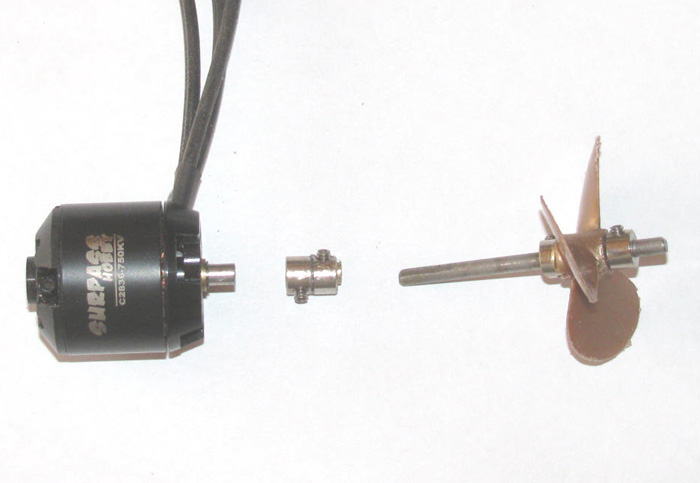
Assembled.
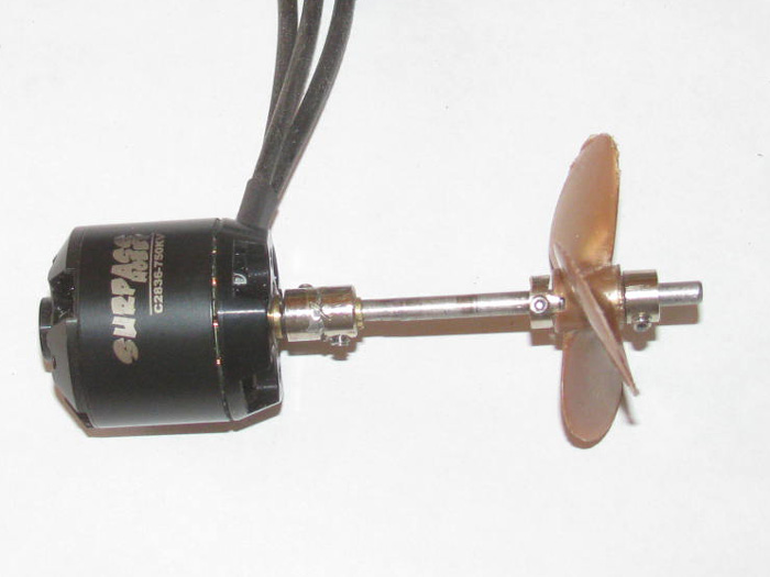
I removed the propeller so the connector an propeller shaft would fit
through the motor bracket.
I cut the motor bracket to fit inside the pod housing.
Checked fit a couple of times.
Soldered on wire extensions that will come up through the rudder post.
Mixed some epoxy and put it where the motor bracket contacts the housing.
The motor is installed on the bracket so I can hold everything in place.
I slide the tail cone on and pushed it in to the pod housing.
Through the front, I push 3 plastic shims to hold the motor centered
in the housing not touching the housing.
This is an out runner motor so the outside spins and needs to not touch
anything.
I cleaned the epoxy off a couple of the motor mount bolts and place
the pod in the small vise to hold the pod where the epoxy will run towards
the bracket and not out on to the table.
Should be ready to put the tail cone and front of the pod on permanently
tomorrow.
February 27th ================================================
To start I looked over the epoxy on the motor bracket.
Removed the 4 screws and worked the motor and it's long wires out of
the pod.
Did a little clean up with the exacto knife.
Mixed a little more epoxy.
With a small screw drive blade, I applied epoxy to the inside of the
motor bracket and smeared it around to make sure the motor housing did
not touch.
Set this in a foam block to hold it upright so the epoxy stays put.
With the motor out, I can work on the motor to propeller shaft connector.
I thought about drilling two holes to insert piano wire and solder for
a more positive joint between the 2 wheel collars.
I did not have a small enough drill bit.
So, I ground a notch on 2 sides and inlaid 1/16" flatten round brass
rod.
Soldered them in place.
Looks good.
Took them to the tool shed and turned the piece in the drill press to
make it round again.
Just cut the tops off the round rod sticking off the end.
Next I needed to drill the brass tube out off the wheel collars I used
to keep them straight.
Yep, this is where it all went bad.
The drill bit grabbed about half way through and the wheel collars
cracked length wise.
Instant scrap metal.
Okay, now to build another connector.
I found the next size up wheel collars.
Thought about jointing the smaller one to the larger one.
Then I found a second large one.
Check fit on motor shaft.
Wheel collar is too big.
But if I put a brass tube shim in the wheel collar that fits the motor
shaft and fits the wheel collar, I have something to work with.
First I make a brass tube piece long enough to hold 2 wheel collars.
Drill 2 holes 180 degrees apart for the set screws to go through to
the motor shaft and propeller shaft.
Now I need a smaller brass tube to slide in to the larger brass tube
and fit over the propeller shaft.
Did I say the motor shaft is bigger than the propeller shaft.
Any way, using the 2 pieces of brass tubing makes the shaft reduction
fit perfectly.
Drill a hole in the small tube to line up with one end of the larger
tube.
Ground and files the tube ends to leave 1/32" sticking out as a bushing
against the tail cone bushing.
Now, I have a connector that requires only the set screws to be tightened.
(no soldering)
February 28th ================================================
Today's progress report.
Working on the motor pod.
Time to check and clean the epoxy on the inside of the pod to make
sure it does not interfere with the motor.
I must be getting better at spreading the epoxy with my small screw
driver blade.
Only a small spot to file down and that is only a precaution as I think
it is not in the way.
I took some 200 grit wet/dry sand paper and wrapped my finger and sanded
the inside of the pod to cut the roughness down.
I had Dremel sanding drummed the inside again to get a little more
clearance.
Put the motor in the pod.
Well that was not expected.
I did not consider the new larger wheel collars would touch the new
motor bracket.
Well, not actually but the set screws won't go through the opening
in the bracket.
Okay, got my big round file out and spent some time filing out the hole
in the bracket.
The I took a small square edge file and filed a notch in the bracket
for the set screws to go through.
This was after I measured to make sure once the wheel collars where
through the bracket the set screw was past the bracket.
I have about 1/16" clearance.
Put the motor in the pod and put the 4 screws in that hold the motor.
Slipped tail cone on to check clearance now that I know the wheel collars
touched the motor bracket.
Yep as I suspected, I need to drill the recess in the tail cone bigger
in diameter.
Out to the tool shed and put the tail cone in the small vise and on
to the drill press.
I clamped the vise down so it would not climb on the bit as the bit
cut in.
I now have a larger diameter recess hole.
Test fit says it is ready to go.
Back to the shop and clean all the dust and cutting off.
Silicone grease the motor shaft and inside the tail cone where the
cup seal is.
Test fit.
I remember I had to turn the tail cone to find the sweet spot.
The spot where the shaft turned the easiest.
The tail cone to pod surface seems to not be square so adjusting is
necessary to get a straight through shaft without binding.
Found the spot and marked the tail cone and pod body.
The original marks are about 1/8" off.
No problem.
I put s light coating of silicone glue on the tail cone joint edge.
Pushed the tail cone against the pod body, turned it back and forth
to get a good silicone spread.
Put the front propeller wheel collar stop on the shaft to hold the
tail cone tight in place while the silicone cures.
The nose goes on the same way but no need to align any thing.
Just put the silicone on, push the part in to the pod bode.
Twist a little to spread the silicone and it's done.
All the parts without the shroud.
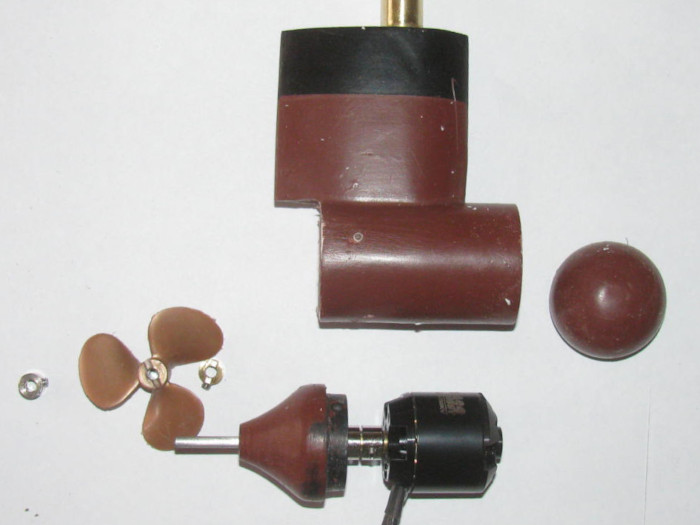
All the parts assembled without the shroud.
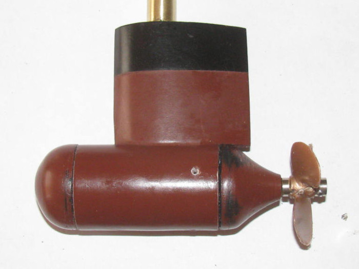
Assembled with the shroud in place but not screwed on.
That will happen after I loosen the propeller wheel collars and get
a bit of clearance between the tail cone and the wheel collar.
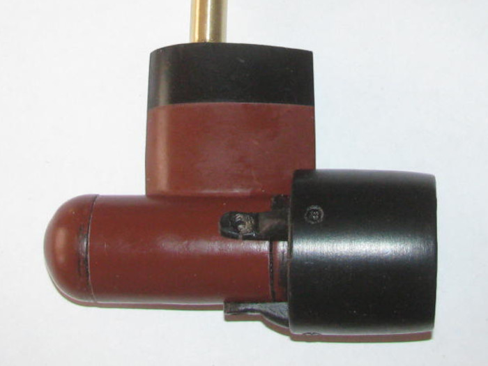
March 1st ================================================
Early this morning I had errands to do.
While out, I picked up some line to try on the steering pulleys.
This afternoon I was able to get in to the shop.
But my plans of a couple hours was not to be.
It seems yesterday when I was in the shop I turned on the heater because
of the cold and high winds.
When I went in the shop today, it was 95F because I forgot to turn
off the heater.
I thought I could hang in there but I was wrong.
20 minutes or so is all I could take.
So this is what I got done.
I installed the pod shaft through the rudder shaft.
I soldered the 3 motor wires to the speed controller.
Covered the wires so they would not touch and short out.
I turned on the Tx and Rx systems.
Checked the propeller rotation.
I got it right the first time.
Checked the high speed. GOOD.
Check low speed for cogging.
There is but it is at the end of very slow rotation.
The slow rotation is more than acceptable.
I checked the solder joints to make sure I had got attachment.
Let them cool and slipped the heat shrink tube over the soldered joints.
I have not shrunk the tube yet.
I did more cutting in the foam for a better point to point for the battery
wires.
This gets rid of the 6" extension wires.
I moved on to the deck pusher bar linkage.
With the wheel collar set screws tight, the pusher bars slip on the
connecting shaft.
I marked the shaft for the set screw locations and removed the shaft
to grind flats on the shaft.
Should not slip any more.
I started to put the motor shroud on the pod but it has been long enough
in the hot house.
I am done in the shop for today.
Tomorrow is more VA surgery.
2 appointments for 2 surgeries.
It will all be good.
March 4th ================================================
Using this photo of the motor pod to show what I am talking about.
I was in the shop today.
Not long but I was able to get something done.
I was assembling the pod shroud.
The pod is installed in the hull so it was awkward at times.
While I was getting the shroud ready to install on the pod, I dropped
it.
2 of the mounting tabs at the front of the brackets broke off.
These brackets where made of plastic.
Not happy about this but no reason to get upset.
Just make new ones.
As I was looking for small scraps of plastic to make 5 layers to shape.
I decided to make the brackets out of 1/16" hard aluminum.
My street sign aluminum.
Happens to be lots of small pieces sitting on the bench from making
other brackets.
Cut 3 3/16" wide strips about 1.25" long.
Drill a hole on one end of each and drill a counter sink for the bolts.
Now it was just a matter of bending the strips to give about 1/4" offset.
(maybe a little less)
I did this trial and error.
Got them made.
Test fit several times.
I am happy with the fit for now.
The propeller has clearance all the way around.
I need to get 3 nuts to go on the bolts as they go through the shroud.
(tomorrow)
March 5th ================================================
The nuts where bought.
Now to assemble and make sure everything fits right and lines up so
the propeller does not touch the shroud.
Mounted the 3 brackets to the shroud.
This requires a bolt, and a nuts.
So far everything is good.
Next to mount the brackets to the pod.
On the second bolt I was having trouble getting the bolt to start in
to the pod plastic threads.
Then I dropped the bolts.
I will look for it later.
I have an extra bolt.
This bolt went right in to the pod threads.
Okay, now I need to find the dropped bolt.
With the flash light, I found it.
I have an extra nuts so I tried to screw the bolt in to the nut.
It would not start.
Got out the 10X power gem loop.
Looked at the bolt and the nut.
Took on of the bolts in the pod out and compared the threads.
Out of 6 bolts, all are fine thread except 1.
I do not have extra bolts.
Well, I do but they are round head and not counter sink heads.
Okay have to get another bolt at the hardware store.
I need to get 3 small washers for the bolts going through the shroud.
I can see the bolts pulling through the plastic.
Going to stop it before it happened.
Disassemble the shroud from the pod.
Sanded all the edges of the brackets round. (no sharp edges)
Painted the parts Satin black.
The shroud only needed touch up.
The brackets will need to be turned over to get the other side once
dried.
Of the 3 brackets, I file 2 bracket holes to shroud to give me some
adjustment movement.
Once on the pod and clear the propeller, I will glue the screws and
nuts in place.
Mark the inside so I know where they go on the pod.
It was very close but I had to force one bracket about 1/32" to 1/16"
to get the shroud away from the propeller.
I should get the pod completed tomorrow.
-------------------------
I looked at the repair on the Gato read cap.
I was relocating bolt threads.
I filled the hole with thin CA and I screwed the bolt in with silicone
grease on the threads. (wiped clean)
Today, after 3 days of curing, only because I forgot about it, I removed
the bolt.
It came out and I have good thread.
The old threads where stripped the first 1/8" in to the hole.
I needed new thread because I could not drill deeper without going
through the end cap. (don't want tha)tt\
So I got more than my 10 minutes in today.
March 6th ================================================
I now have the last pod bolt.
I am repairing the over sized hole in the shroud.
While doing this, I thought I would try something new.
I have not had a phone for 20 years but because of the VA hospital
stuff, I ended up getting a cell phone.
I use it mainly for texting because what I had for 20 years was e-mail
and this is as close as it gets.
Anyway, the phone I bought was mainly for the camera.
Today, I thought I would try making video.
So this is my second every phone video.
I will see how it goes.
It is 15 seconds long.
I see I need to figure out how to make the dpi smaller.
The video is jumpy while loading but smooth when ran the second time.
pusher
bars video
March 7th ================================================
Yesterday, I repaired the shroud where the bolt pulled through making
hole over sized.
I taped the inside and filled the outside with CA and baking soda.
Did it is 3 passes to make sure it cured all the way through.
Today, I filed and sanded the outside of the shroud.
Redrilled the hole for the bolt.
Hand turned a drill bit to counter sink the hole.
Repainted the shroud.
Watching the video of the pusher bars in operation, I noticed that the
bars do not come up to 90 degrees to the deck.
So I looked it over and found where I could file a little material
off the pusher bars so they would go to 90 degrees.
I thought the file would remove the material easily.
I was wrong.
I had put plastic sheet on the step of the pusher bars so filing the
plastic did not do well.
A file on the flat plastic acts like a bearing surface and the file
slides but does little cutting.
So out comes the sanding drum on the Dremel and I carefully sanded
the part down.
Did it slowly and test fit often.
This took some time because I had to install and uninstall the pusher
bars to do this testing.
Now it looks like I have the 90 degrees.
Got the Tx out.
Reset the limit on the servo to get the pusher bars to the right place
without putting a strain on the servo.
While I wait for the new servo to arrive, it seems all I am doing is
small details to the hull.
While I had the radio out and on, I spun the propeller and trimmed 1/64"
of the blade ends.
Basically making the propeller blades all the same length during spinning.
That gives me an additional 1/32" clearance in the shroud.
Time on the barge to day is about 1 hour.
March 12th ================================================
I did a little work on the motor pod day before yesterday.
Got it painted and then assembled including the shroud.
---------------
Today, I was in town and one of my stops was the Post Office to pickup
bills.
Opened the box and there were the bills and there was the servo.
The servo that is scheduled to arrive in mid April.
Got home and took the servo out to the shop and unpacked it.
Put on the barge so I could plug the servo in to the Rx.
Powered up the Tx and Rx and tested the servo for 180 degrees.
Well that is not what I expected.
I got about 90 degrees total..
Did some research and found out that the servo is setup for 180 degrees
but the Tx signal does not support the signal needed to get the 180 degrees.
Checked for options.
I found 2 that I can do.
1. Open the servo and add two 2.2k to the potentiometer (about $5.00)
2. Order a servo adjustment circuit to put inline with the servo. (about
$20 and has the ability to adjust the throw)
I am going to look in my parts box and see if I have 2 resistors at
that value.
I am thinking what I have are capacitors and not resistors.
Anyway., tomorrow if the weather turns a little warmer, I will be putting
the barge in the test tank to get a waterline and to test the motor pod
thrust.
March 13th ================================================
I started to mount the rudder servo in the barge.
Turns out the control horn is not the same size as the other servo
arm I use to make the pulley to fit.
The pulley I am referring to are the three parts on the right.
This is a photo of the first fitting using the horn from the other
servo.
The new horn is a little bigger in overall diameter and the curves
on each side near the big end are shallower.
I have to knife the hole diameter bigger and cut the points of the
curves.
Was not a big job.
15 minutes of scraping and test fitting until the horn dropped in with
a little pressure.
The fun part was the small plastic disk to the left of the horn is
already glued to the notched plastic piece.
I have looked at several hardware store for a longer bolt that screws
in to the servo drive shaft.
No luck.
The fix was to make a plastic disk to drop in to the large hole on
the notched piece and glue it in place.
I had to remove plastic through the big hole down to the smaller disk
and cut out 1/16" of plastic to allow room for the plastic disk on top
of the control arm without making the control arm stick out proud.
Got it done using the drill press, a flat bottom cutting bit and setting
the depth for the cut.
5 minutes.
Test fitting says it will work so I assembled the plastic parts.
Test fit in the barge to make sure I got the two pulleys lined up.
All is good, now.
I was going to float the barge to get a waterline and test the motor
pod.
Not really cold outside but the20 to 35mph wind is not comfortable.
Besides, I would not be able to get a waterline with the wind whipped
waves in the test tank.
Wait for tomorrow ans see if it gets better.
Weather says middle of the week, temps will go up and the wind should
be gone.
I can wait the wind out.
March 14th ================================================
It is still windy but not as much as yesterday.
I am going to float the barge.
While filling the test tank with water, Test fit the rudder servo and
it's pulley.
I needed to cut a couple of small notches for the Allen bolt heads
that stuck out past the cut already in the pulley.
Done.
Tank was fill not to the top but enough to give 1" to 2" under the motor
pod.
This left most of the barge below the top edge of the tank and shielded
it from some of the wind.
Turned on every thing. (I did a power up test in the shop on the bench)
Placed the barge in the water.
What I see was not expected.
The stern is low and the bow is high.
Went and got a second battery
power pack.
This was NOT enough.
Went and got 1 of the steel ballast plates that go in the ALMA.
This was enough to bring the barge to level.
The waterline is much deeper than I thought it would be.
But I can live with it.
I have another plastic hull that I will float to see where it sits
with no nothing in it.
Just to get a reference.
I was going to get a mark for the waterline for paint but now I think
there will be no waterline needed.
Tested the pusher bars.
Work as designed.
Then the forward and reverse of the motor pod.
Good response.
I do not know what the speed will be but in the short tank it looks
more than acceptable.
First
water test video
-------------------------------------
Now for the failures.
Back in the shop, I removed the ballast weight and deck.
I turned the hull upside down to check for water in the pod.
Sure enough, a little water came out of the rudder post.
When I assembled the pod last week or so, I though this might happen.
The tail cone did not feel like it slid together right.
(but knowing brushless motors came run under water without being sealed,
I did today's test)
The fix is simple enough.
Un solder the 3 power wires tot he motor.
Remove the motor pod from the hull so I can get a look all around.
Remove both the nose and tail cone and clean off all the silicone and
start fresh.
While the tail cone is off, clean and re grease the propeller seal.
March 16th ================================================
Back to the barge.
Un soldered the motor to speed controller.
Removed the brass pin that holds the rudder post in the rudder through
tube.
Removed the motor pod from the barge.
Took it in the house and filled a pan with water. (enough to get the
pod under water for leak testing)
Applied air pressure to the rudder post. (this will pressurize the
motor pod)
Lower the pod in to the pan of water.
Looks like a fish tank aerator. (yep, it leaks)
When I assembled last week, I had emptied the silicone glue tube and
I was using a small screw drive to reach in the tube to get glue.
I did not get a lot and was trying to spread it around to make the
seal.
I usually put lots of silicone on the joint to where the glue squeezes
out. (it didn't)
So today I have to clean all the old silicone off.
Sand a file the surfaces to make sure they are clean.
Time to removed the propeller and it's 2 wheel collars.
Exacto knifed the front cap and tail cone.
Pull the cap and tail cone out of the pod body.
Remove the 4 bolts holding the motor in the pod.
Pull the motor out and carefully pull on the 3 wires making sure not
to pull them out of the motor. (I actually pushed the wired down the rudder
tube)
Exacto knifed the silicone of the pod edges and the inside of the pod.
Finally got to the sand paper and file.
Next, I removed the three screws that hold the propeller shaft cup seal
on place in the tail cone.
I looked for a photo but I do not have one.
The tail cone is 2 pieces with the seal between the pieces in a recess
cut.
Cleaned all the old silicone grease off the seal and out of the recess
in the tail cone.
Re greased the recess and cup seal.
Reassembled the tail cone. (Glad I put index marks on the parts)
Made sure the propeller shaft connector wheel collars are tight and
put the motor back in the pod.
Spun the motor to make sure the wheel collars do not touch the motor
mount bracket. (good to go)
Put the pod in the small vise to keep the front of the pod up.
This new silicone glue is different. New and Improved.
It is thinner and runny.
I applied the glue to the bow cap ledge and shoulder.
Put in the pod with a little twist to spread the silicone.
As I push the cap in to the pod, I got the need silicone squeezing
out of the joint.
Much better than lat time.
I will leave the pod in the vise and let the silicone cure before putting
the tail cone in.
Going to read the label on the new and old tubes to see what the difference
is.
Oh, one difference is the tube has a tapered application nose where
the old one had the tapered nose but it could be unscrewed to get to the
tube directly and to clean out the tapered nose off the tube.
I looked around at my lead weight blocks I use for ballast or making
ballast shapes.
Found 1 that weight about the same as the steel ALMA ballast weight.
Of course it is smaller than the steel block and will fit better under
the pusher bar linkage.
March 17th ================================================
The resistors ordered to make my high torque servo in to a 180 degree
servo were in my mail box.
After doing the in town errands, I went out to the shop.
This is what I got for $3.22 for 80 2.2K resistors.
This project will require 2 resistors.
Here is where I got them.
https://www.ebay.com/itm/324083572997
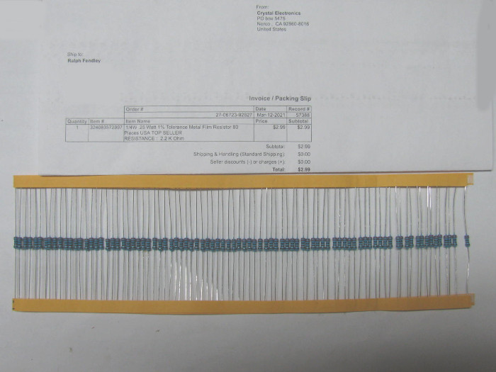
First, I siliconed the tail cone on the motor pod.
Put it in the small vise to cure. The front cap seal nicely.
Now for the servo.
Here is the servo before I make the modification.
Control stick centered.
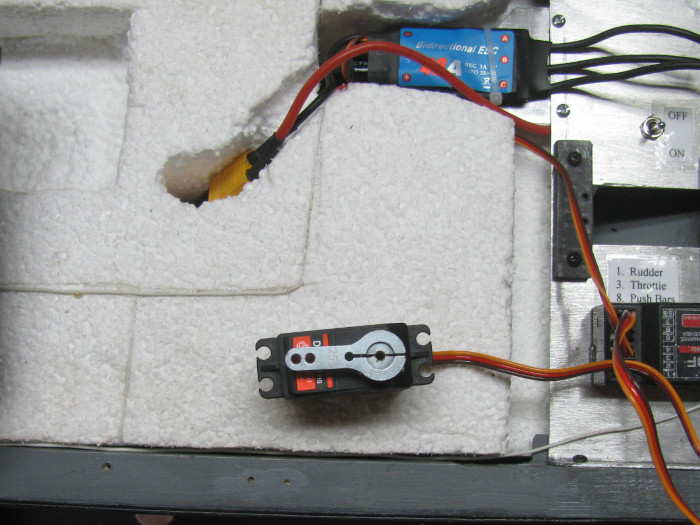
Full left on the control stick.
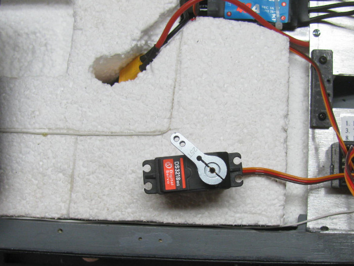
Full right on the control stick.
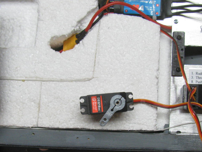
I get about 60 degree right and 60 degrees left of center.
I opened up the servo removing the bottom cover.
Pull the control board out enough to see under the broad.
I want to see the control resistor pot.
There are 3 wires going to the pot.
I will be cutting 2 of the wires and adding in a 2.2K resistor to each
line.
The wires to be cut are the outside wires, leaving the center wire
as is.
Get 2 resistors and cut the end wires short for soldering.
I left about 1/16".
Tin the wire ends and the resistor wire ends.
Carefully solder the resistor making sure to keep the resistor on the
same wire.
Best way is to do 1 wire at a time so there is no confusion.
I slipped a short piece of shrink tube on the wires before soldering.
After soldering I slipped the shrink tube over the resistor covering
the end wire connections.
This high torque servo has lots of empty room in it but this can be
done with the mini servos we use.
Total modification time. About 20 minutes.
Time to test the servo.
Control stick centered.
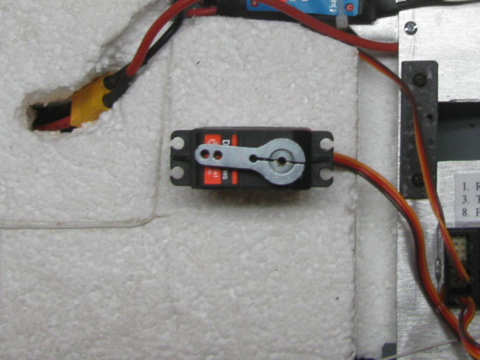
Full left on the control stick.
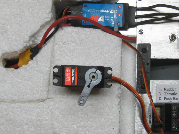
Full right on the control stick.
It appears I am getting about 160 degrees of movement. (useable)
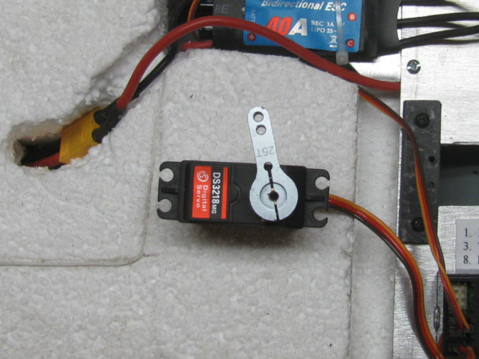
I am using a Futaba 9CAP Tx for this boat.
It has programming that will allow me to change the servo end points
from 0 to 140 percent.
Let's see what this will do.
Control stick centered.
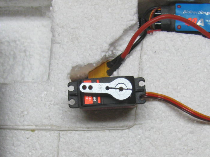
Full left on the control stick. (140%)
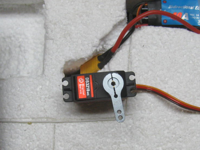
Full right on the control stick. (140%)
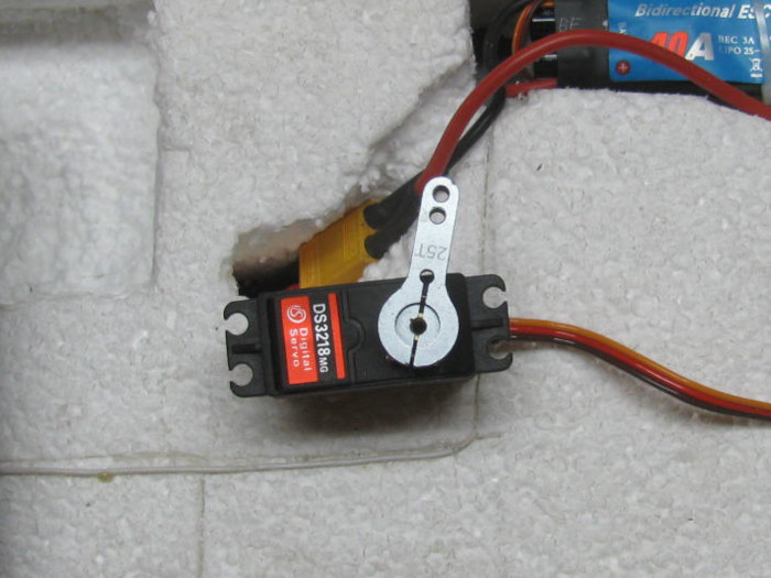
Using the Tx computer adjustments, it looks like I can get 190 degrees
and a little more.
This will do everything I need to do with the steering.
I reset the servo to 90 percent so I do not break any thing when I
install the steering system.
I will adjust it slowly aft installation.
Installation will happen as soon as I finish the motor pod sealing.
March 18th ================================================
Early this morning, I put the propeller and wheel collars on the pod
motor shaft.
I checked the shroud for alignment and then installed with a drop (3)
of silicone glue over the bolt holes.
I Check the shroud and propeller clearance. (GOOD)
I lifted up the barge and slipped the wires then the rudder post in
to the rudder post bearing.
Put the top pulley and it's safety brass ring in place.
Got out my soldering iron to reconnect the 3 wires.
The iron was hot and I was ready to solder.
OH NO!
There are only 2 wires coming through the rudder post.
Looked on the bench and then the floor.
Got down on the floor and looked under the bench.
And there the 3rd wire was laying. (NOT GOOD at all)
Looked over the wire and see that the wire separated from the motor
short wire at the solder joint.
The shrink tubing was still on the motor wire.
Easy enough to fix.
Completely disassemble the motor pod, I had just sealed up.
Even tested it for leaks.
Clean all the old silicone glue off the nose and tail cone
Clean all the silicone from inside the pod body.
This requires Exacto knife, sanding and file scraping.
Cut the shrink tubing off the wire.
I see the original wire broke off at the solder joint.
Remove wire insulation.
Tin the clean wire.
Get the table vise out and setup for soldering.
Do the soldering.
Check the joint.
Check the other joints.
Shrink the tubing over the joint.
Check the propeller shaft tight in wheel collars connector.
Put the motor back in the pod body.
4 screws and tighten.
Silicone on the nose part and slip in to pod.
Twist to spread silicone.
I used lots and it squeezed out all the way around.
Wipe off excess.
Add a little silicone grease on the propeller shaft.
Put silicone glue on the tail cone joint step.
Put it on with twisting to get the shaft to go through seal and then
to spread the silicone glue.
Line up the index marks on the pod and tail cone.
Push the tail cone on to the pod.
Wipe off excess silicone.
Again good coverage.
Set pod in small vise with propeller shaft sticking up.
The pod will slip in the vise "V" groove.
I put 5 pounds of weight on the propeller shaft push the tail cone
down and the pod down on to the nose piece.
That is how I left it.
Around 11 am I went to the big town.
I went to an RC off road racing store and track.
I went looking for 2 sized of Allen wrenches so I could tighten the
bolts on the new high torque servo and for the odd Allen screws I have.
The store had them but I am not buying the fancy long with plastic colored
handles at $19.95 each.
They do not have the standard "L" Allen wrenches.
Left there and went 2 block to Harbor Freight.
Same problem. Only have fancy plastic handled wrenches.
On way home, I stopped at an O'Reilly's auto parts.
All they had were sets of 6 to 10 wrenches in a package.
I opened 2 packages.
Metric and Standard to test the wrenches on the bolts I brought with
me.
Found one to fit.
1/16".
So I bought the package of 10 for $4.
Now I can make sure the bolts are tight.
I had made a wench but it was starting to round off and become useless.
Today did not go as planned.
Rebuild motor pod and drive some 38 miles one way to town to get a
$4 wrench.
So that is how my day has gone.
Parts are sitting on kitchen table for work in the shop tomorrow.
March 19th ================================================
I got a late start in the shop.
What I got done.
The motor pod has been reassembled.
The pod has been installed in the stern of the barge.
The 3 wires have been soldered to the speed controller.
Was easy because I marked the wires so they would go back together
the way they were when I took them apart.
The horn has been installed on the servo.
The servo was installed in the bracket on to the electronics tray in
the barge.
The pulley was installed.
I made the last plastic part that goes on top of the pulley to keep
the control line from running off.
Glued it in place.
Once this cures, I will install the control line that will turn the
motor pod.
The line is made up and waiting to be installed.
Tomorrow morning, I hope to finish this up.
Photos to come.
Maybe a video of the steering in action.
March 20th ================================================
Last start in the shop.
Put the planned steering system on the rudder post and servo.
It works for about 4 minutes.
Then the line used was cut and failed.
Tried it again making sure not to cut the line.
Again the line cut.
It appears to be the clamp I made to hold the 2 end of the line.
Okay, I will try an o-ring.
My o-ring was a little short but I could stretch it to go over the
two pulleys.
This did not work.
The o-ring slips.
Okay, tomorrow I will go back to the cable instead of the 20 pound line.
As a last resort, I can use brass rod linkage and not have the 180 degree
turning of the motor pod.
-----------------------------
I may make a paper drawing of the steering post and servo.
I can draw a 3/4" and 1" pulley over the centers and see how long a
gear belt would be.
Convert it all to metric and then maybe I can find a belt and gear
drive that might work.
==================
Tomorrow if I can not get the cable to work, I will make up the brass
rod linkage parts so at least I h ave a working boat.
March 21st ================================================
The issues in not the system but the cable I am using.
It is fishing wire leader and it does not bend around corners very
well.
I needed to pull a lot of tension.
Going around the 1" pulley I have on the rudder post was not easy.
This morning, I had it all assembled and working.
I also anchored the cable on the rudder post pulley and then again
on the servo pulley.
After about 5 minutes, I started seeing slack in the cables.
My servo pulley had started coming apart.
My pulleys are made from plastic sheet (1/16") glued together to build
up to about 3/8" thick.
It appears the cable got in between 2 layers and cut though the joint.
What are you using for the cable/line between the pulleys? (belt?)
Maybe that would help.
I am now looking through the tool shed to see if I can find a couple
of blocks of aluminum (I know I do not have brass blocks) I can make new
pulleys out of.
I do have blocks of gray PVC plastic I could use.
Something else I found while digging in boxes.
I found several different size nylon gears from old cars.
I found 3 that would span the distance.
Only there are 2 big and 1 small.
I would have to cut a notch in the back of the engine cover for the
gear to run.
If I can find another small gear, that would work.
I would like to find two 1" diameter and one 1 7/8" diameter.
There is a RC indoor track about 35 miles away that is open on Tuesdays.
about noon.
Maybe I need to go for a drive.
===============
I went back out to the shop.
I dug through old rejected end ca[ps.
Found one that had enough center to make a clean pulley.
This was an end cap that was used in the Skipjack 3.5" cylinder.
I need a clean 1" disk.
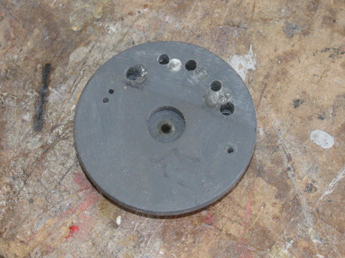
Out to the tool shed and made it happen.
Here is the disk still on the 1/4" bolt I use as a spindle.
I need to measure where the groove should be to line up with the servo
pulley.
Before cutting the groove, I will turn the servo disk so I can fit
them and line up the grooves.
On the left is the original pulley with groove and and upper ledge
with holes for brass rod clip
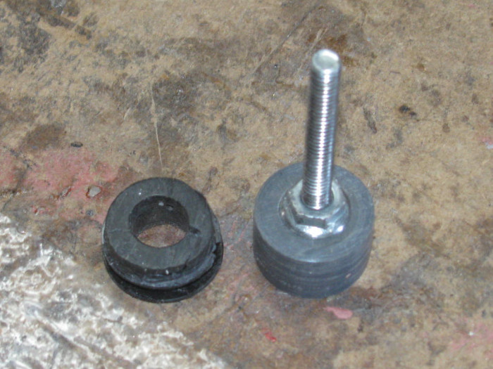
The PVC cuts really easily.
I may still look for aluminum to make these pulleys.
March 22nd ================================================
This morning, I cut and turned 8 disks to make new pulleys.
Before making the disks, I measured the room under the deck cabin.
Looks like I may have to cut a slot at the back of the engine cover.
I am making the pulleys bigger in diameter.
The servo pulley will be 1/4" bigger in diameter and the rudder post
pulley will be 1/2 bigger in diameter.
Both pulleys are now the same size.
Drilled the center holes.
Some where 1/4", one was 5/16"+ and some where 9/16"
Depending on whether they go on the rudder post or the steering servo.
After drilling the disks, I stacked them keeping the correct holes together
so I could put a steel shaft through the holes to keep the disks straight
with each other.
Both pulleys are in vises to keep pressure on the plastic while the
bonding cement does what it does.
After it all cures completely, I will test fit in place and make sure
to get the two pulleys on the same level plane.
Looking over the original pulleys, I found that the disks where the
cable cut through had not been put under pressure in the vise.
This left a small gap the cable found and cut through.
Yesterday when I posted the failure, Greg suggested putting screws through
the disks near the edge to give them more strength.
Greg, I will be at the hardware store tomorrow and I will be getting
small screws and most likely small bolts to go through the disks.
It is a simple addition that will keep the disks from separating.
March 23rd ================================================
I finished the rudder post pulley.
The pulley is the bottom and there is a top that is to give more bearing
surface.
I put a brass tube inside to join the two parts.
Glues them and pinned them.
Drilled the brass keeper pin holes through the brass tube using the
holes in the top piece as my guide.
The 2 pieces where glued together yesterday and clamped over night in
the small table vise.
In the photo the new pulley is on the rudder post and the old smaller
part is there for size comparison.
I did not take the photo at the right angle to show the screw in the
pulley to hold the steering line.
I did test it for strength and I could not pull the line through when
the screw was tightened. (moderately)
The photo on the right shows the pulley sticking out the back of the
deck house after I cut the slot.
I will make a cover later after I get everything working.
Probably make it look like steps to get on to the engine cover.
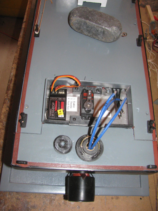 .... ....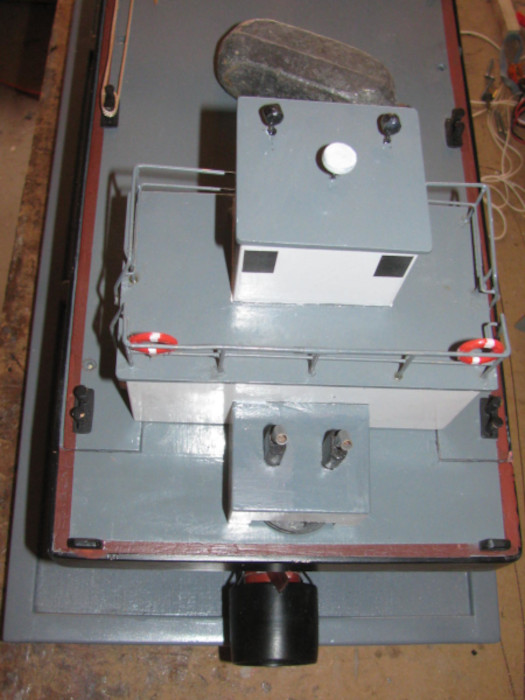
The servo pulley was made yesterday but not jointed to the bottom piece
that connects the pulley to the servo.
The small vise was being used.
The pulley and the base are now in the vise under pressure to cure.
Work will continue on Thursday.
Tomorrow is VA surgery day.
I have 2 appointments with 2 different surgeons.
This is an on going never ending thing.
Spent most my life outside working and playing.
Now I pay.
March 24th ================================================
Home from VA by 2pm.
All good.
The first surgeon did several cuts on my wrist and arms.
Second surgeon looked at what he did 3 weeks ago and said I didn't
need to come back unless something goes wrong.
Came home, had lunch and out to the shop.
Started by finishing the servo pulley that was in the vise from yesterday.
Mounted the pulley on the servo and started putting the line that will
work the rudder.
Here it is installed.
The line has not been trimmed yet.
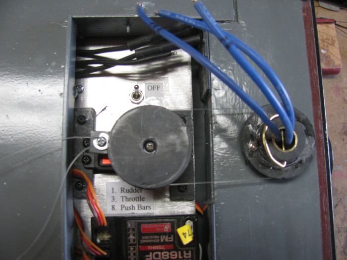
Time to test the system.
Lots of photos coming.
First three are with the Tx control set at 100% on servo rotation.
Tx control centered.
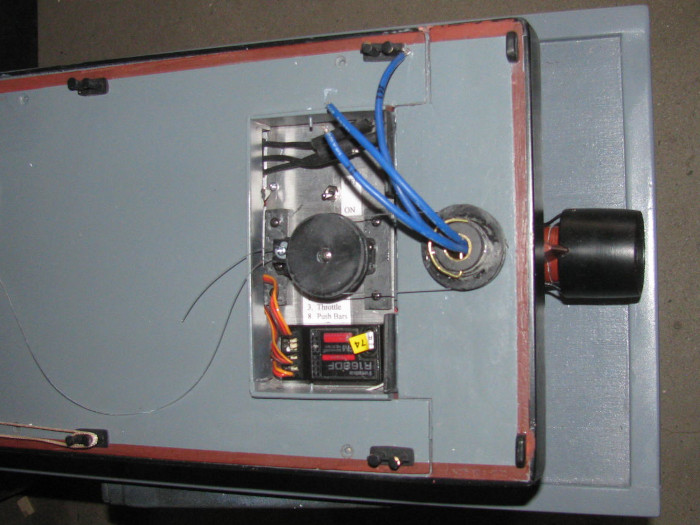
Control stick, full right.
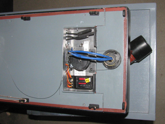
Control stick, full left.
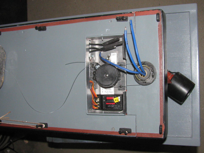
While I had the system running, I opened the Tx menu and reset the servo
from 100% to 135% by watching the rudder turn.
It now turns just past 90 degrees.
No need for center, so here I have
Control stick, full right at 135%.
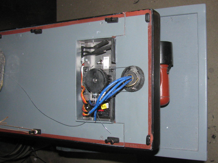
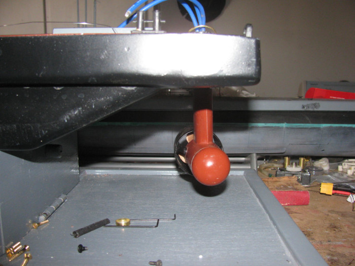
Control stick , full left at 135%.
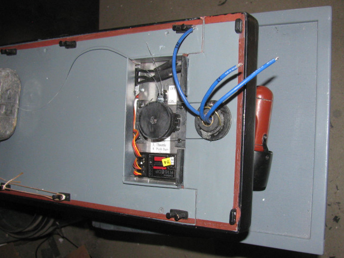
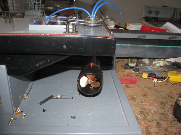
I now have what I wanted all along.
Trim the line and check line retaining screws snug.
Put the deck house on and I think I am done.
There is more touch up painting but I can live without doing that.
It's a working barge.
Oh. . . Thought I would try the phone video again.
Rudder
testing video
March 25th ================================================
Yep! the barge is done.
That was yesterday.
Today, I was in the shop making a modification. (of course I was)
Looking at the barge and the photo, I do not like the alignment of the
two pulleys.
The rudder post pulley is lower than the servo pulley.
It all works fine but I see the line dragging on the pulley edge on
both pulleys.
I do not want to be running and have the steering line cut and
loose control.
Turning the rudder post pulley over, the alignment is almost straight
in line. (less than a 1/32")
I tried to figure a way to make the original pulley work but there
are so many holes from rerouting the line that there is not much plastic
left to work with.
Thought about cutting the pulley off the hub but that was more work
than making a new pulley assembly.
So, I did. I cut plastic squares and then turned them in to disks.
(2 sizes as needed)
This afternoon, I have been glue the disks together on a 1/4" shaft
to keep the disks centers straight.
Just glues the hub to the pulley disks.
In the vise under a lot of pressure.
I cut a short brass tube to go over the rudder post that will be glued
in the pulley assembly.
Once cured, I can drill the 1/16" hole through the hub for the brass
pin that will hold the pulley on the rudder post.
I will have to be careful drilling the holes through because the motor
wires are already in the post.
My plan is to put a piece of smaller tubing down through the post with
the wires going through the smaller tube.
The smaller tube should stop the drill bit from getting to the wires.
I will drill from both sides.
Tomorrow there will be drilling.
March 26th ================================================
Here are both the original and new rudder post pulleys.
Basically they are the same except the new one has the pulley groove
near the top and the original has the groove near the bottom.
The pulley with the groove near the top puts the steering line in a
more straight line pull.
The original pulled down enough to rub on the pulley edge.
The small screw is to capture the steering line so it does not slip
during operations.
There is a screw at the front of the servo pulley that captures the
steering line ends and allows me to put tension on the line so there is
no slack.
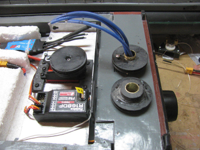
The pulley installed.
There is a brass 1/16" rod going through the pulley and the brass steering
tube post.
You can see just the very end of it.
There are modified wheel collars on each end to hold it in place.
I sanded both sided of both wheel collars flat so they would go under
the pulley and not drag on the deck.
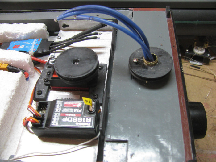
In this photo the steering line has been installed.
Checked for pod centered on hull and tensioned.
Only need to solder the 3 speed controller wires to the motor wires.
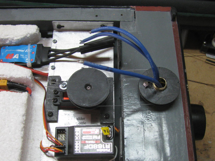
After finishing the steering system, I got out my paint bushed and started
doing the touch up painting.
Spots like on the hull edge behind the pulley.
On the upper corner and other places around the hull.
Tomorrow my plan is to solder the wires.
Once that is done, I think I am going to call this Rescue Barge build,
COMPLETE!
Barge will go in to it's transportation box and wait until I can schedule
a day at the lake. (soon, I hope)
Wait! Like always, there is one more thing.
I need to mount the weight in the bow to make the hull sit level in
the water.
Right now it is just sitting under the foam and can slide about.
1 minute job. (drop of silicone glue and put weight in place. Then DONE.
===================
Only thing I can think of are photos from running at the lake
March 27th ================================================
The speed control to motor 3 wires are soldered and tested.
Motor runs in correct directions.
Built the small cover that will hide the edge of the rudder pulley.
Is attached to the deck house engine cover.
A bunch of small plastic pieces glued together and shaped.
It measures about 9/16" high by 5/16" deep by 1.5" wide.
This is currently clamped to the engine cover to cure.
Should be able to paint it tomorrow with a little touch up on the deck
house.
---------------------------
I have 3 deck lines I want to either coil or lay back and forth on
the deck.
Glue them down so they do not fall off the deck in to the water and
possible get caught in the propeller.
I have a test length to see how I will lay them.
Coiling does not seem likely.
When I tried to coil the test piece, it would not go tight enough to
look right and as soon as I moved my fingers to get a better hold, it uncoiled
faster than I could stop it.
Something to work on after painting.
-----------
Here is a photo from when I was building the deck house.
Here is the extension box over the steering pulley.
I needed just short of 1/4" more engine cover to get over the pulley.
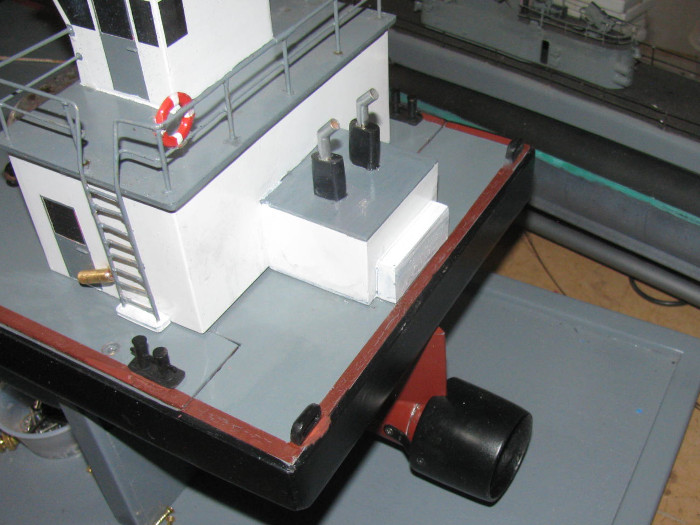
March 30th ================================================
Got the white paint yesterday.
This morning the touch painting got done on the back of the deck house.
Only thing not in the photo is I put the number 74 center of the pilot
house under the center window. (Why 74? It is the frequency the barge is
on)
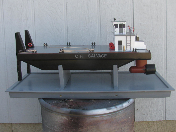
.
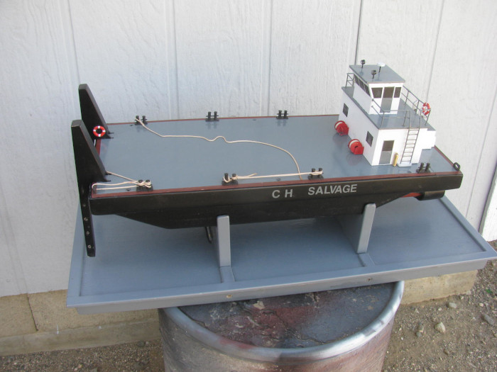
.
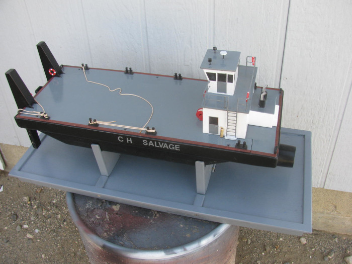
April 3rd ================================================
I have been doing other stuff and Thursday/Friday I was sick with food
poisoning.
It lasted about 17 hours.
All is very good now.
I want to clean off the work bench to get the Gato back in play.
I needed to return to the water trimming of the barge.
It sits about 1/2" high at the bow.
Last time in the water, I put a steel weight which goes in my ALMA
schooner and it did the trick.
But the schooner wants it's ballast block back.
It's a matched set of 6 blocks.
Okay, I have several different size lead blocks I cut to put in sub
hulls.
There is one close in weight to the steel block.
Fill the test tank half way and put the barge in the water.
Put the lead block about where I thought it should be.
I was 3/4" too far back from the bow.
slide it forward and the bow dropped.
Dropped past the level line.
No a problem.
Just start sliding it back until I get level.
The weight was just sitting on the deck so moving it was just a matter
of pushing this way or that.
Barge is level, take a measurement from the bow edge.
Could not have been easier.
2" exactly.
In to the shop.
Remove the deck house, deck and the flotation foam block.
Turn the block over and cut a slot in the foam for the ballast weight.
Silicone glue at 4 spots on the bottom of the block.
Put the foam block back in the hull and place the ballast block in
the cut in the foam before setting all the way down.
I put a 1/4" strip of soft packing foam on top of the flotation foam
over the weight to hold down pressure.
(When I charge the batteries again, I will removed the soft foam)
Put the deck on and the deck house.
Oh, I got the tow lines glued on the deck.
No worrying about them falling over the side.
Now I can move the barge off the work bench.
April 10th ================================================
Off to the lake.
Rescue Barge out for it's first run in the pond.
Skipjack out after 18 months out of the water.
Arrived at the pond at 7:10am.
Took about 10 minutes to unload and move to the park bench at water's
edge.
Panorama
Looking West.
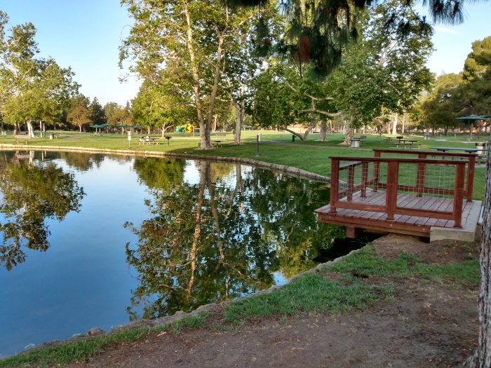
Looking South.
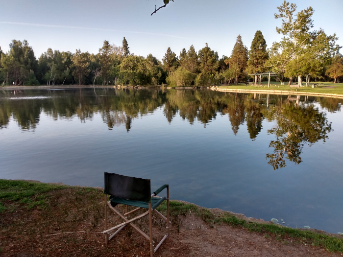
Looking South East.
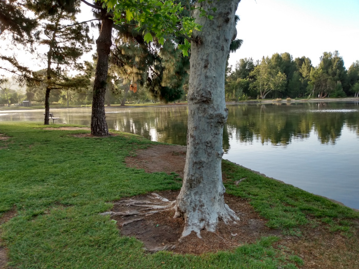
Removed the deck house and turned on the power. (Tx is on)
In the water it went.
Noticed that launching at an angle has water over the hull rail and
could put water in the hull.
Took it out of the water and turned the barge on it's side.
No water came out.
All good.
Back in to the water making sure not to tip the barge on edge.
I tested every thing.
Forward, reverse, pusher bars down and tilted.
Then speed tests.
I have the Tx set to 30% on speed.
It looks like it will do nicely.
Not fast but it will get there quick enough.
Brought the barge up close so I could see what is going on while testing
the new 90 degree plus steering.
I tested with motor in forward and in reverse.
Oh boy! It does exactly what I was working for.
The following is the video of the testing.
Barge
at the lake test video
At .06 minutes the new 90 degree rudder with motor running forward.
Both directions.
Turning in place.
A little forward drive to test steering.
It is very sensitive.
At 1:10 minutes the barge is again turning in place.
But the difference is the motor is running in reverse.
At 2:00 minutes I tested the pusher bars.
At 2:14 minutes I ran the barge in reverse.
Total run time on the barge was about 20 minutes.
After retrieving the barge, I took the deck house off and turned the
barge up side down.
I had about a table spoon of water come out of the rudder post and
pod.
I need to work on the pod and get it sealed completely.
========================================
Now the Skipjack.
Turned on the power and closed up the hull.
Once in the water , the stern was high.
It took 3 dives to shake the bubbles loose.
Then a couple rounds on the surface then work down to periscope depth.
Here is a pass with the masts exposed.
Ran this way at will.
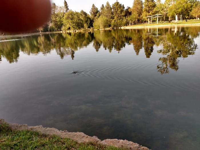
Now for a run at periscope depth.
This was a bit touchy as I had only about 3/8" of the periscope above
the water.
When I took the photo, the periscope was not above the water but it
was making a wake.
A little up on the fair water planes and there was the tip of the scope.
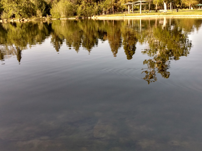
It is not easy running the boat and taking photos.
I can see the boat without glasses but have to put glasses on to see
the cameras.
After about an hour running the Skipjack, I started having issues with
trim.
As long as I had forward motion the boat was trimmed perfectly.
When I cut power the stern would come up and broach the surface.
When I powered up, the stern would drop and then recover as speed got
the stern planes working.
I know this issue.
There is a little water in the cylinder and it is sloshing back and
forth.
Brought the boat in and opened it up.
Turned off the power and then lifted the cylinder out to look at the
bottom.
There was the water.
Not much but enough to call it a day.
I removed the front end cap. There is nothing attached to the front
end cap so it comes out with no problems.
Drained the water.
Put the cylinder back in the hull without the end cap.
Closed up the hull and made ready to transport home.
I will look over the Skipjack for leaks and I think I will find a crack
in one of the rubber control rod boots.
I find it the boots sit they crack and need replacing.
Now for the summary.
Barge tested great.
Small leak in pod.
I will find it.
Skipjack ran like it was suppose to until it got water.
This has happened before.
Can be fixes n 10 minutes if I find the crack.
All in all a good day at the lake.
I feel much better now.
April 13th ================================================
I did not work on any boats since Saturday.
About 20 minutes ago, I went out to the shop and removed the motor
pod on the barge.
After a 20 minutes run there was about a spoon full of water in the
pod.
Not a problem but I rather there be no water.
After removing the pod, I did some work on the wiring.
I have soldered and un soldered these 3 wires so many times, I had
to come up with something a little easier.
I cut 3 short brass tubes that just slip over the bare wires.
I am going to solder the tube between the connecting wires
The tubes are a bout 1/4" long.
Now when I solder the wires together, I just have to heat one end of
the tube and slip the wire in.
Slip the covering shrink tube over the joint to protect.
Now to find the pod leak.
Took it in to the house.
Filled a small deep bowl.
Put the pod in the water and blew steadily in to the rudder post.
A few bubbles coming up.
I looked all over the pod and only found bubbles at the front of the
pod.
This is an easy fix.
The front of the pod is a slip in fit with silicone sealant.
I must not have gotten enough sealant to fill any small gaps.
With an Exacto knife, I cut around the front piece.
Then with a flat screw drive, I separate the front from the pod.
Clean the pieces with the knife and a small file.
This takes about 5 minutes. (lots of practice during building)
Letting it dry completely from the water bowl test.
I will reseal in about an hour.
Will water test in the morning before reassembling on the barge.
April 14th ================================================
The front of the pod has been resealed.
Did that late yesterday evening.
Finished water testing in bowl.
NO air leaks.
Now to install the pod back on the barge.
This takes about 10 minutes.
Slide the rudder post through the stern block.
Slip the pulley over the rudder post keeping the steering line in the
two pulleys.
Get down low so I can see the holes in the rudder post and pulley shoulder
line up.
Push the pin through.
Put the wheel collar keeper on the pin.
Pod now installed.
Solder the new brass tubes (1/4" long) to the 3 motor wires.
Solder the 3 speed controller wires in to the tube.
Let cool and slide the heat shrink tubing pieces over the new connectors.
DO NOT shrink.
Allow to slide but keep the connectors insulated.
Motor pod leak sealed.
-----------------------
While I have the barge on the bench, I am going to check the percentage
of movement.
I noticed the servo chattering.
Usually means the servo has moved to a point that the movement is being
stopped before the servo is to it's stop.
Change the servo percentage from 35% to 25% and start adjusting from
there.
Fully down the percentage is 32%.
At 33% the pusher bars hit the deck.
Fully up at 34%.
At 35% it was hitting the deck.
The chattering is gone.
The Rescue Barge has been repaired and is back in it's transportation
box.
Only needs batteries charged before next trip to pond.
---------------
There is now room on the bench to look in to the Skipjack cylinder.
I will reassemble the cylinder then out to the water tank for testing.
Just the cylinder.
I will put the test rubber hose on the Schreader valve at the front
so I can blew pressure in to the cylinder while looking for air bubbles.
==============================
I have opened up the Skipjack.
Removed the cylinder.
Out to the test tank.
Powered up everything.
IT all works correctly.
Put the cylinder in the water and held it down to the bottom.
8" of water.
Cycled the piston ballast tank instead of using the rubber tube to pressurize
the cylinder.
Sure enough, air bubbles coming from the rear planes rubber control
rod boot.
In to the shop and opened the cylinder and removed the rubber boot.
It has a crack at the small end where the 1/8" brass tube goes through.
Replaced it.
Also straightened the control rod because it was hanging up on the
motor frame.
Assembled the cylinder and back out to the test tank.
Again I have bubbles but this time it is from the rudder control rod
boot.
In to the shop.
Removed the boot. (with out having to open the cylinder)
Checked the boot.
No cracks.
Slipped the boot on to a short length of brass tubing.
I could not get it to leak by blowing on it.
Back out to the test tank.
This time while pressurizing the cylinder, I twisted the boot on the
control rod.
This stopped the bubbles.
But now I get bubbles at the end cap through tube.
I now know what the problem is.
The brass tubes have corroded enough to not let the rubber seal.
In the shop I removed 1 boot and cleaned the brass tube.
Put the boot back on and out to the test tank.
This boot now is sealed.
So the plan is to remove the 3 boots and clean up the brass tubes and
control rods.
This boat has sat for over 18 months without use.
Got to do a little maintenance.
I should have it gone in a hour or so.
Tomorrow's work.
January 19, 2022 ===================================
Rebuilding Z pod due to motor speed control failure.
No low speed and jerky.
New system will be a brushed motor.
Requires new pod to be build.
The new pod has been built.
The original nose will be used.
Some how I can not find the tail cone assembly after modifying for
the new brushed motor.
After 2 days and about 3 hours looking, I decided to make a new tail
cone.
If I find the original one, I will have a spare.
New tail cone plastic parts have been glued up and turned to shape.
Right to left are : tail cone to propeller cone.
The ring with the big hole in it is for the cup seal which is above
the part.
The next disk is the cover for the cup seal.
The left ring slips in to the pod.
Tail cone and cup seal ring will be glued together.
The disk and ring will big hole will be glued together.
The 2 assemblies will be held together with 3 small bolts.
Before gluing can be done, I need to cut and fit the 2 brass tube bushings
in the tail cone and the compression disk.
I have about 6 hours in it but most of that time was waiting on glue
to cure before I could spin the parts in the drill press to shape them.
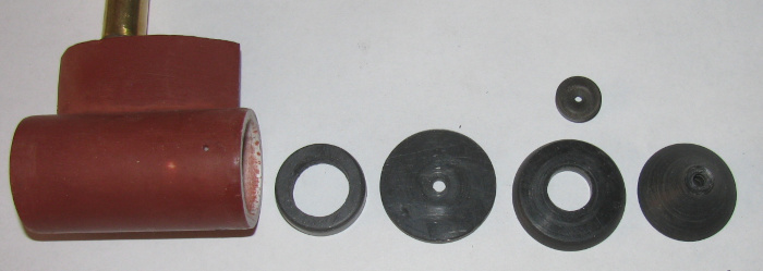
January 21, 2022 ===================================
Finished making the new tail cone.
Here al the parts.
Left to right.
Pod body.
Front of tail cone with flange that goes inside the pod body.
Cup seal.
Tail cone end with recess for cup seal.
Shaft and propeller and wheel collars.
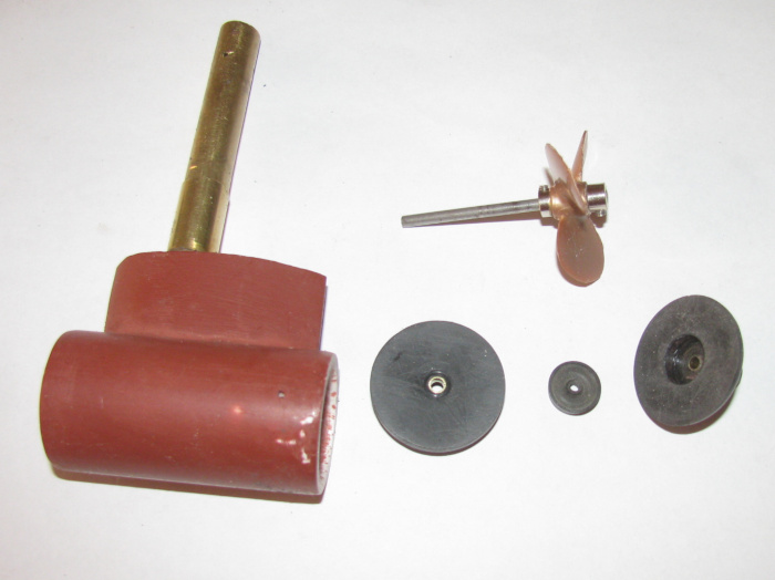
Parts on propeller shaft.
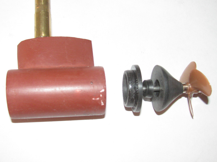
Tail cone end with cup seal in recess.
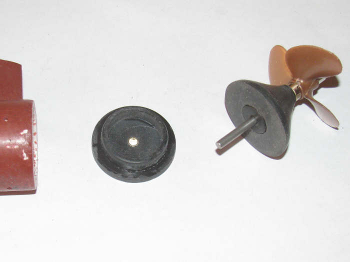
Parts again on propeller shaft squeezed together.
There is a small gap between tail cone end and front piece.
This is caused by the cup seal and will be pressed out when I install
the 3 small bolts that will clamp the cup seal in place.
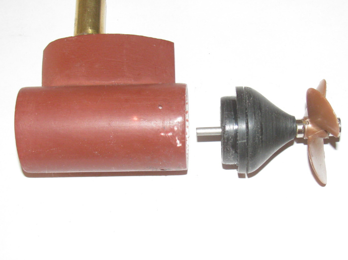
Tail cone assembly in the pod body. (sorry the photo with the nose
in place did not come out clear)
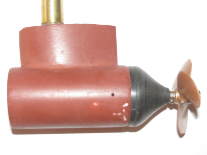
I am currently cutting parts to make the motor to propellers haft connector.
And I need to drill for the 3 small bolts that will be inside the tail
cone to hold the parts together.
January 22nd ==================================
I finished making all the parts.
I have finished fitting all the parts.
This morning, I drilled the seal pressure plate and tail cone for the
3 small bolts that will compress the cup seal in the tail cone.
I made the motor to propeller shaft connector.
Motor has a 1/16"+ shaft and the propeller has a 1/8" shaft.
Couple of pieces of brass tubing and 2 wheel collars.
Ground flats on the two shafts for the set screw to bite.
Test fitting the motor in to the pod.
Needed to grind some of the pod plastic away for the 2 power wires
and motor to slide in together.
Was a tight fit before grinding.
The wires would go in but the wires pushed the motor over to one side
off center.
The grinding a slot did the trick.
Everything fits nicely now.
The tail cone assembly needed a little glazing to get ride of some small
voids in the layers of plastic.
Once that cures, I can sand it to finish.
Paint the tail cone and front end to match the pod. (primer red and
then hand rubbed to make it have a glossy look)
I should be able to assemble the pod tomorrow.
Put the pod back in the hull and install the new control horn.
Run the two power wires to the new DPDT switch that will do the reversing
of the motor. (new speed controller does not have reversing. not a problem)
Will get more photos while assembling is done.
January 23rd ==================================
Here are all the Z pod parts.
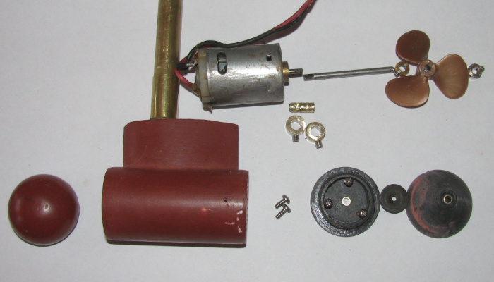
Motor shaft and propeller shaft connected.
Motor installed in pod.
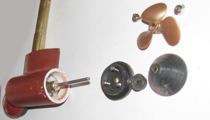
Test fitting the tail cone.
It has to fit without binding.
It took some filing and even a little sanding with the Dremel to get
the tail cone to fit flat to the pod without binding the propeller shaft.
After fitting I disassembled the tail cone.
I applied silicone grease to the tail cone cup seal recess and the
cup seal itself.
Reassembled the tail cone pressure plate to the tail cone with the
3 small bolts.
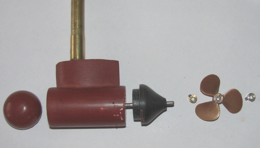
I applied silicone glue to the nose shoulder that goes inside the pod.
Slid it in while twisting to smear the silicone so the shoulder and
edge where covered with silicone glue.
Turned the nose until it fit centered on the pod.
Did the same with the tail cone.
The tail cone actually has an mark for indexing the tail cone to the
pod.
The best fit with the least resistance for the shaft.
Before installing the propeller, I need to loosen the wheel collar against
the tail of the pod as it is holding with a little pressure the tail cone
in the pod while the silicone cures.
I will move it to get a 1/16" gap so the wheel collar will not touch
the pod bushing.
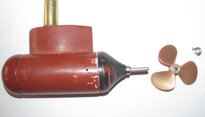
The new Z pod is done.
January 24th ==================================
Tested the pod for water tightness.
A bowl of water and I blew in to the rudder post which goes in to the
pod for the power wires.
Lite pressure and I see no bubbles in the bowl.
Earlier today I brought the paint in to the house to warm it up.
After testing for leaks, I dry off the pod and lightly sanded the entire
pod.
Wiped off the dust.
Taped off the rudder post and propeller shaft.
Got the paint from in the house.
30 seconds later, the pod is painted with red oxide primer. (bottom
red)
Removed the tape and placed the pod in the hull upside down to dry.
When I first put the pod together, the propeller shaft had a hard time
starting.
I know the pod bushings are straight to each other, there are 2, I
think the compression on the cup seal is tight on the propeller shaft.
I know the cup seal is full of silicone grease so I decided to run
the motor 100% for a few minutes.
I have now done this several time while working on the pod.
The motor now starts up easily.
The binding has been reduced.
Only thing left is to install the propeller on the shaft and install
the nozzle shroud.
The 3 bolts go in to the pod so I need to make sure to apply silicone
glue as I install.
January 25th ==================================
Z pod painted. (red oxide primer)
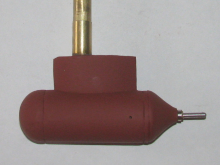
The primer has been buffed to a gloss.
The nozzle has been installed with silicone glue at the 3 attachment
points.
The pod has been installed on the hull.
A view looking down on the electronics tray.
Left to right.
1. Rx
2. Rudder servo
3. DPDT switch made from 2 SPDT switches and the servo to operate the
switched to get reverse. (no reverse on the speed controller)
4. Speed Controller.
In front of the rudder was a recess that needed to be filled. The rudder
post pin wheel collar kept falling in the recess and stopping the rudder
from moving.
I put a piece of sheet plastic in the hole and flushed with the deck.
No more rudder problems.
February 21th ==================================
An update.
The new pod works well.
Getting use to the reverse switch was not hard at all.
The barge has been in the lake twice since motor modification.
Three rescues.
These rescues have show there is an issue to fix.
The motor at 100% power is sort of slow.
This cause slow reaction to turning when pushing the distressed boat.
Sub or surface craft.
I need to find a higher rpm motor of the same size.
But while I look for different motor, this one will do fine as long
as I am patient with it's slow speed.
I have also modified the deck.
To charge the battery, I had to remove the deck to get to the battery.
I was worried that I would eventually strip the threads in the wood
frame that hold the deck to the hull.
So I looked it over and decided to cut a hole in the deck to get to
the charging wires and charge balancing wires.
Once I had the hole cut, I needed to cover it.
I made deck clutter stuff.
I made 12 - 55 gallon oil drums on pallets.
I made 2 wooden crates of different sizes and I made a scale 1000 propane
tank.
Decided where I wanted these on the deck so that the foam blocks that
hold the barge down in the transportation box would not be interfered with.
Got it done.
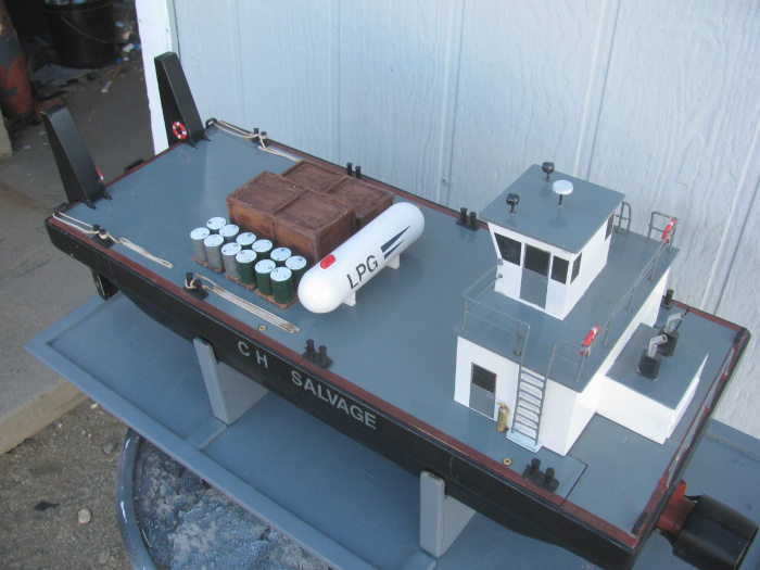
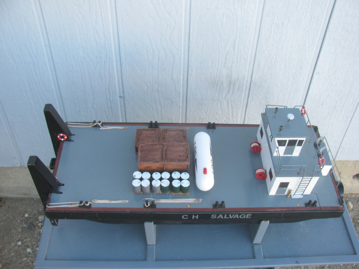
|