I did the sanding.
Made some adjustments to the Mast Gizmo guide rods.
(Got super glue on one of them and the brass tube would not
slide all the way on. Removed it and made another)
With the repair completed, I sanded and filled the two little spots
on top of the sail where the rods got through.
Touch up primer.
Lunch.
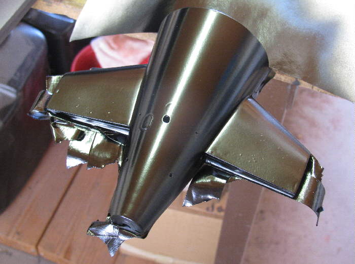
Final sanding and then some black paint. Nice ... except some fool
touched the exhaust housing trying to stand the sail up to dry.
I now have more sanding and more priming and more painting to do on
the exhaust housing.
I am beginning to think I should just leave all the dents and dings
and scratches and call it, Returning from patrol look".
Looking at the photo, I see a vertical line below the waterline at the
aft end of the exhaust housing. Will inspect Tuesday.
It feels like I am going to have enough filler and paint on this boat,
I cloud have changed it's class.
This morning I was in the shop redoing the sail. I got a piece of new
sand paper. The one I had been using was filled with old primer and paint.
Got my sanding block and a rag wet with water. I started in taking my time.
Turned out I had enough paint and primer on the sail to sand out the dents
and scratches without the need for glazing. Oh joy!
Went to town and did town stuff. Came home and again went to the shop.
Looked over the sail to make sure I didn't miss anything eye catching.
Checked the wind out side and found a place where I was shielded from all
moving air.
Shook the life out of the black paint spray can to make sure I didn't
get an thin or thick paint splotches.
The results are acceptable to me.
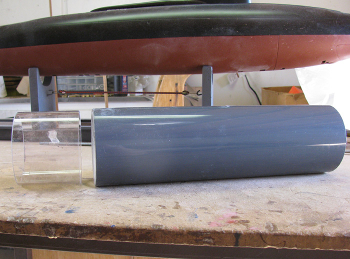
I have put off building the cylinder for as long as I can.
I have to make end caps.
I bought a 12" piece of PVC rod some time ago.
Now I need to cut it and then turn it to size.
The PVC rod is 1/6" bigger in diameter than the outside diameter of
the cylinder.
This should be fun.
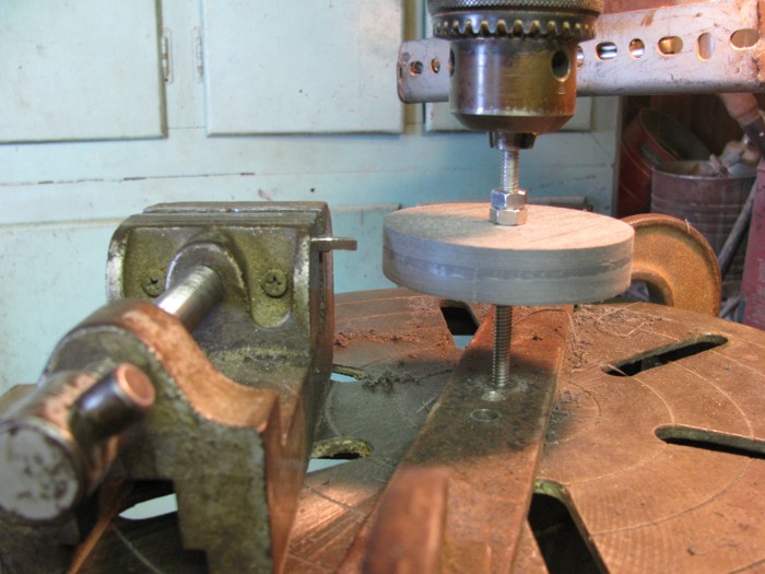
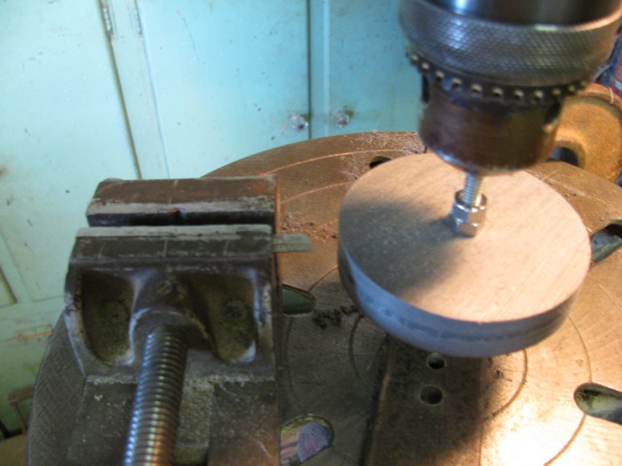
I'm going to cut a 1" piece from the rod.
Put a 1/4" hole in the center and use that as a guide to turn the cap.
More photos as I start the process.
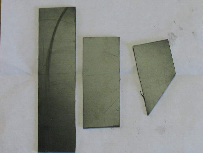
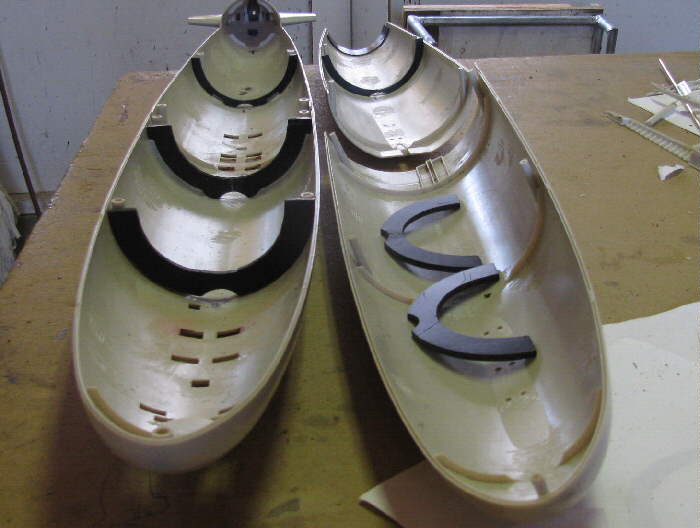
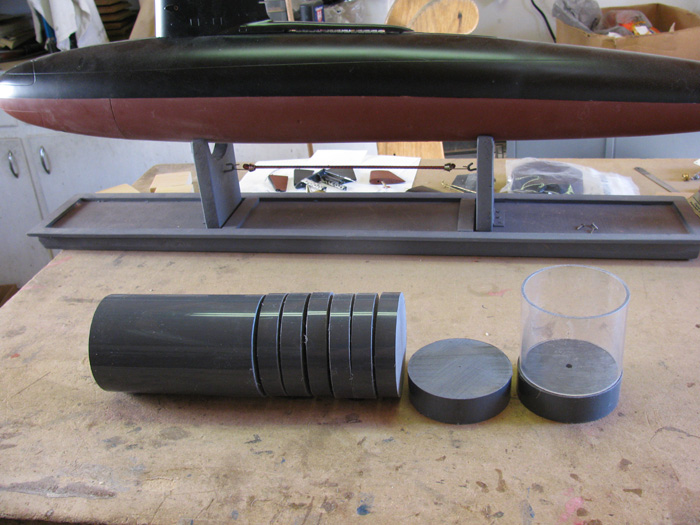
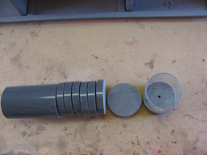
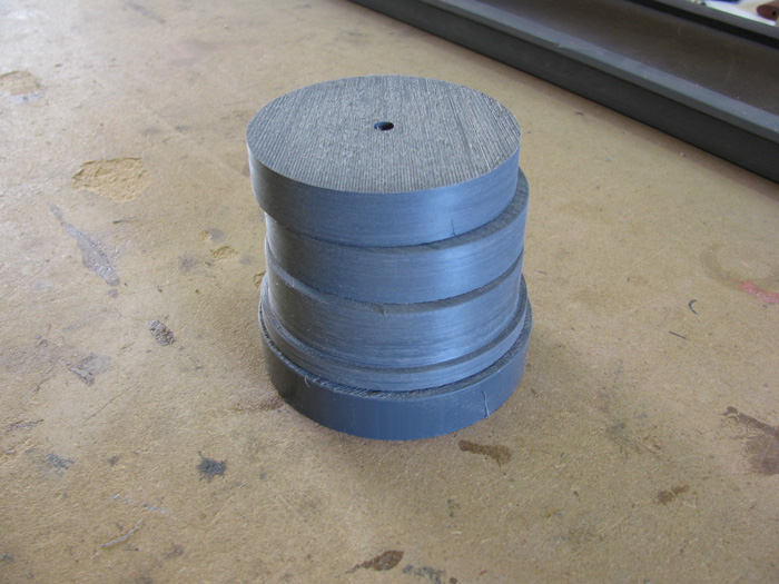
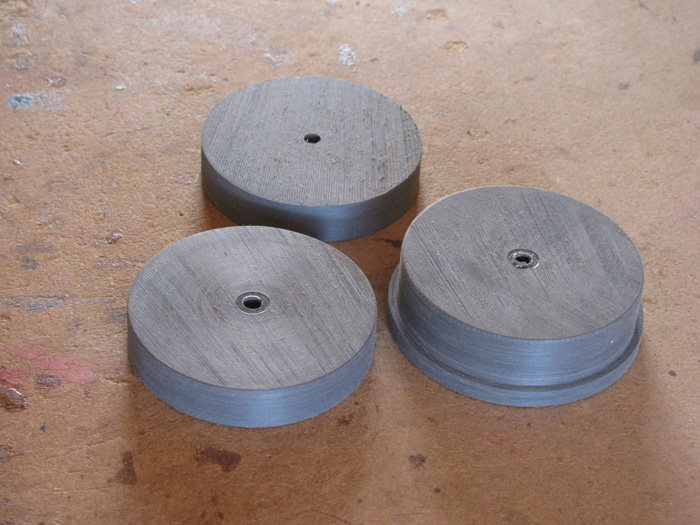
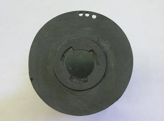
I have cut the disks for the three boats less one end cap as it is a
bit different.
More on that when I get to it. (Gotland will requires special end caps)
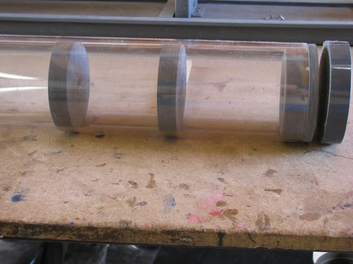
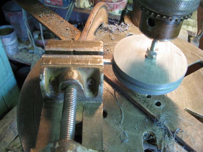
The two disks laying down are 1" thick.
The others are 5/8" think.
This may not be the finished thickness but it's where I am starting.
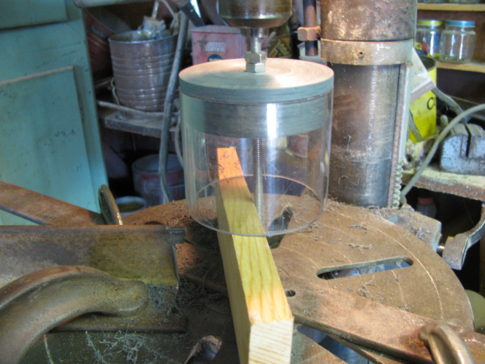
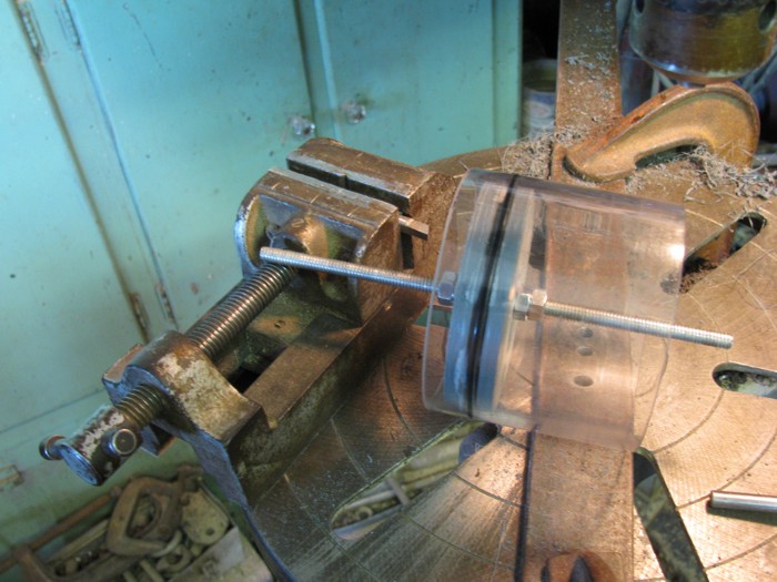
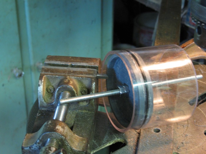
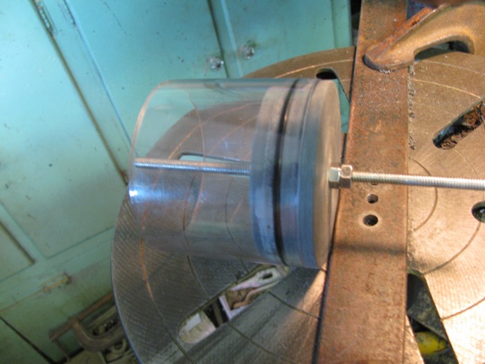
The clear cylinder is the piece cut off the Skipjack cylinder.
I didn't need the full 24".
Makes a nice piece to do the cap sizing with.
Don't have to worry about damaging the boat cylinder.
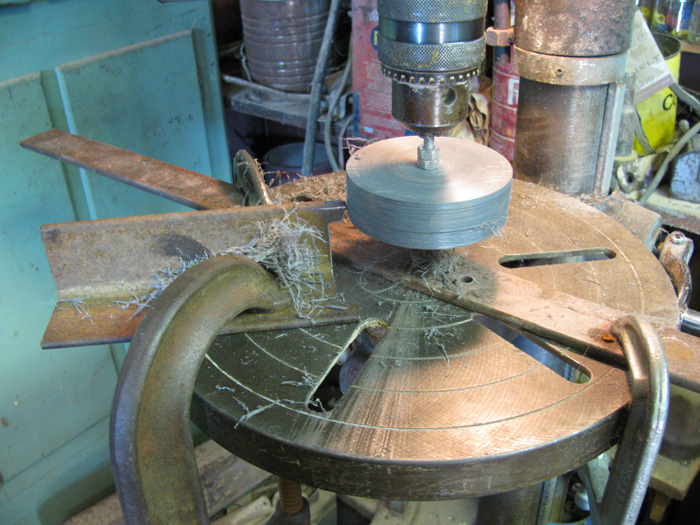
Next project is to make tool that I can clamp on to my drill press table
that will be the cutting tool.
The cutting tool will be stationary and I will use the drill press
to move the cap up and down to remove material.
After each cut I will move the tool in just a touch until I get close
to where I need to be.
Then I will use a backstop to add .001" shims to move the cutter in.
That's tomorrow's project.
10:45am and the shop has reached 100F.
Here's what happened so far today.
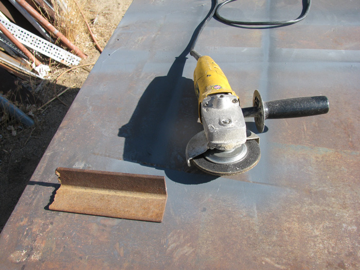
Got out to the shop early while it was cool.
Found a piece of angle iron that would do what I wanted.
Got out the 4.5" grinder.
I cut the bad end off to make it square.
Then made a band saw cut not all the way through. Then I took the grinder
and removed the center piece leaving tabs sticking out.
Now I need to find some 3.25"x1/8" O-rings.
The other end of the cutting angle iron has a tab that has not been
shaped yet.
I will do that when the O-rings are in hand.
The tab will have a shoulder on each side of the cutting section.
The shoulders will control the depth of the cut. If I need it deeper,
I will move the shoulders back as needed.
This will allow me to just run the cutter in until it stops on the
shoulders.
Cutting the first groove will go slow as I check everything.
I have a couple of practice caps for this.
It took me two hours to make the cutting tool and turn 1 end cap and
6 internal caps.
Each cylinder will use three caps.
Still have one custom to make once I get there.
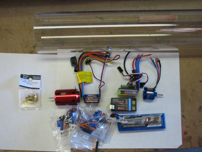
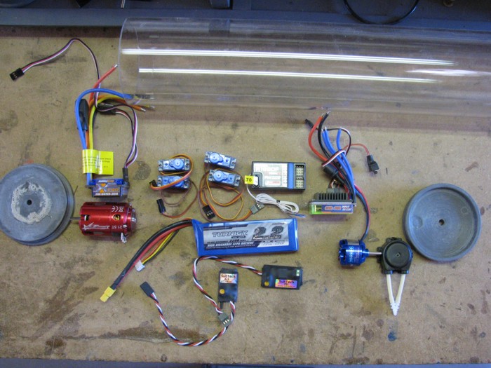
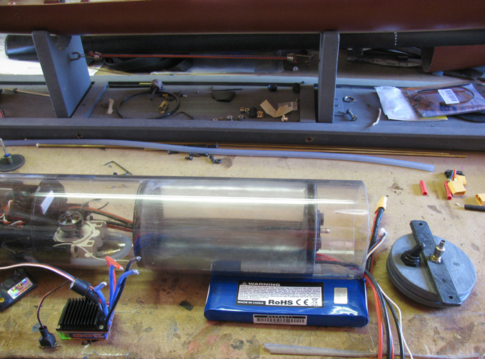
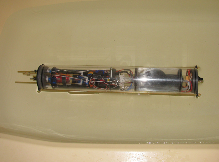
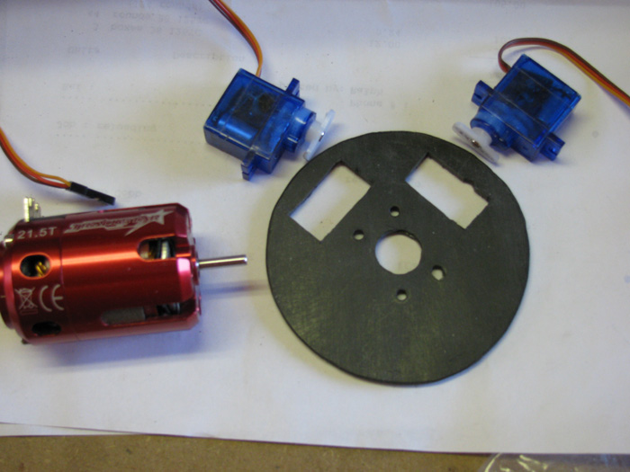
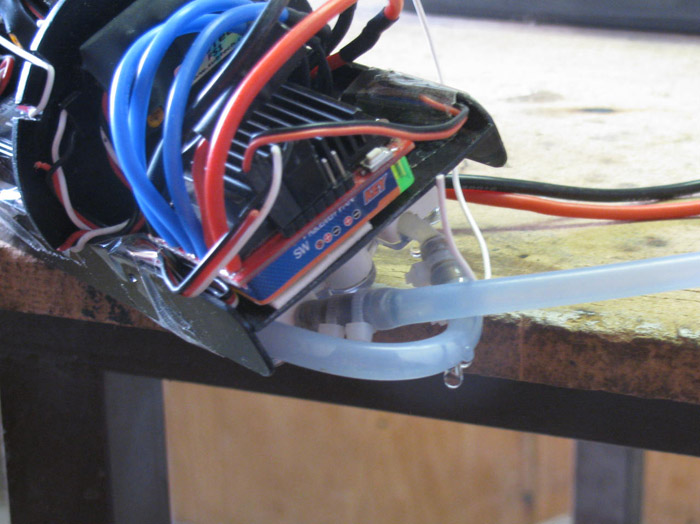
Here's photo of most of what will go inside the cylinder.
Missing are the Auto Leveler, Lost Signal fail safe, a shaft connector
for the main motor.
What's there. . . . left to right ----->
1. Dog Bone universal for propeller shaft outside the cylinder.
2. Main motor Brushless sensored.
3. 35A ESC (main motor)
4. 5 micro servos (below main motor)
5. 30A ESC (ballast motor)
6. 8 channel Rx (below ESC ballast motor)
7. Ballast motor Brushless non sensored.
8. battery pack (below Rx)
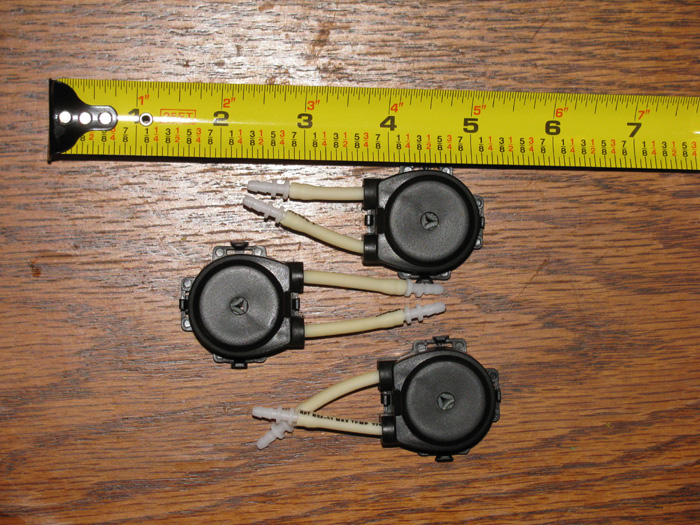
Still an issue with finding a suitable water pump.
Well earlier this morning, during a little chat with Matt and Tim,
I have decided to take on building my own roller water pump.
Can I do it. Won't know until I try.
I have been waiting since Feb for three pumps I ordered.
I can't continue the build without the pump so I am going to dive in.
There are only two out comes. Good working pump or a bunch of parted
assembled in to a paper weight.
I have a question of sorts.
Power switch?
The two ESC each have their own off/on switch and I will need a battery
disconnect off/on switch.
With a battery disconnect switch, can I just ignore the switches on
the ESC(s)? Just leave them on.
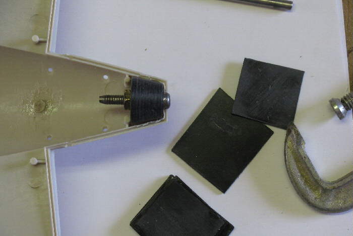
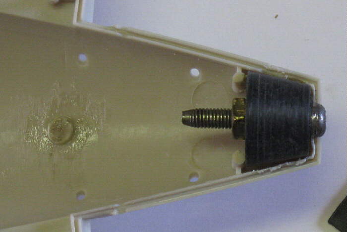
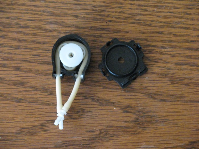
Note: I thought the ballast pump motor was broken when I took it out
the box. I have never worked with brushless motors and didn't realize that
the case spins around and only the shaft end is stationary when mounted.
Surprise, surprise.
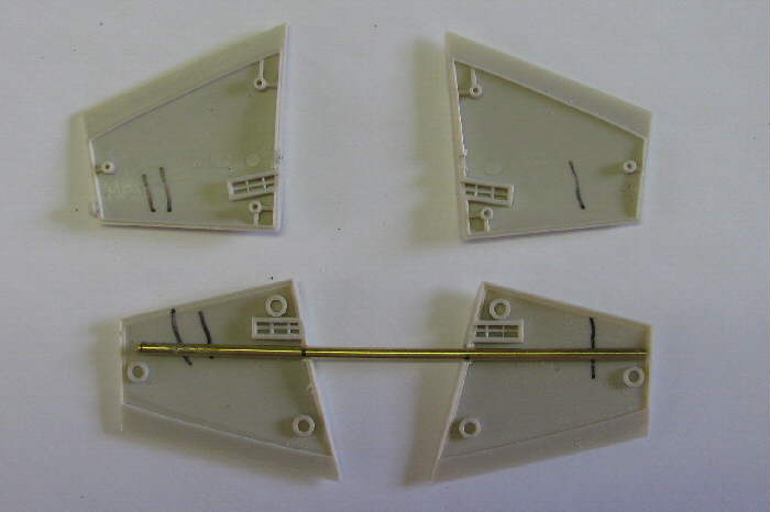
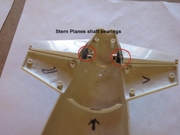
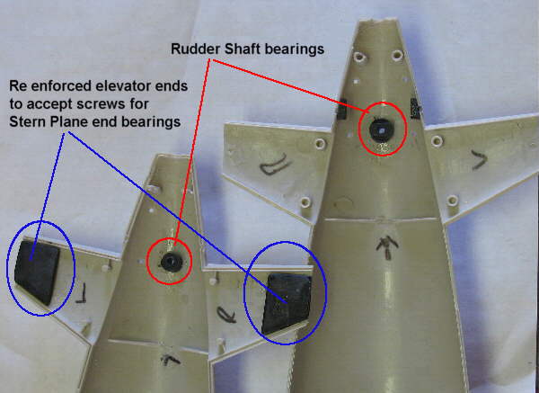
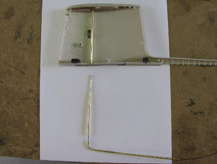
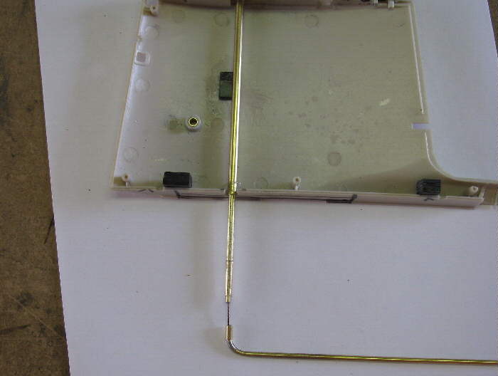
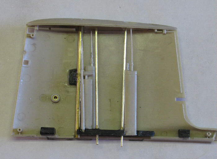
Sail Plane linkage and in sail bushings.
 |
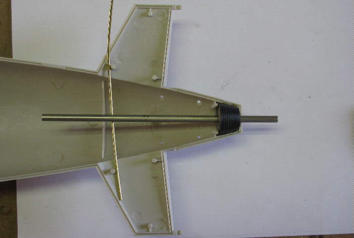
Shaft bushing glued in place and shaft.
 |
Shaft sitting in place. It will not be fixed in place but held there
when the sail is screwed on the hull.
 |
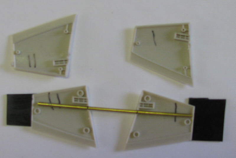
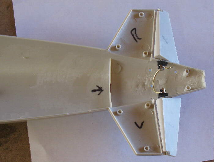
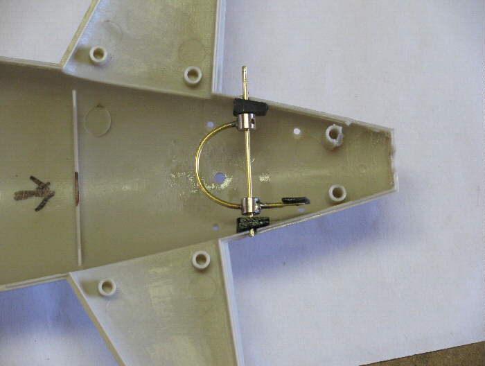
Linkage sitting on sail.
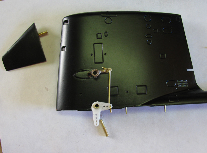 |
Sail planes installed in upper control arm. Lower arm hanging out bottom
of sail. When the sail is placed on the hull the linkage shaft will be
put in bushing and the hull will hold it there.
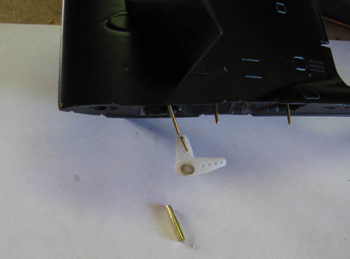 |
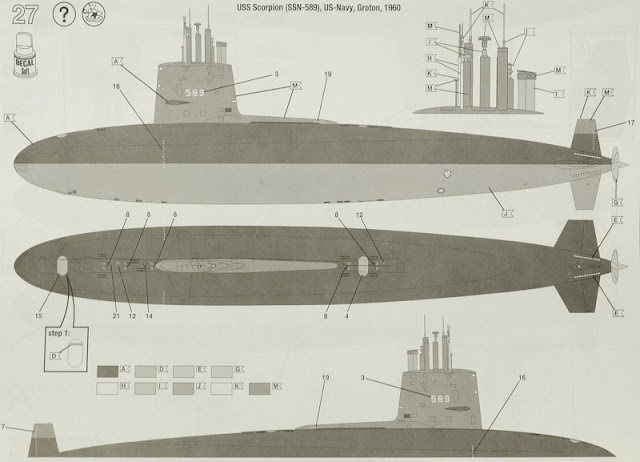
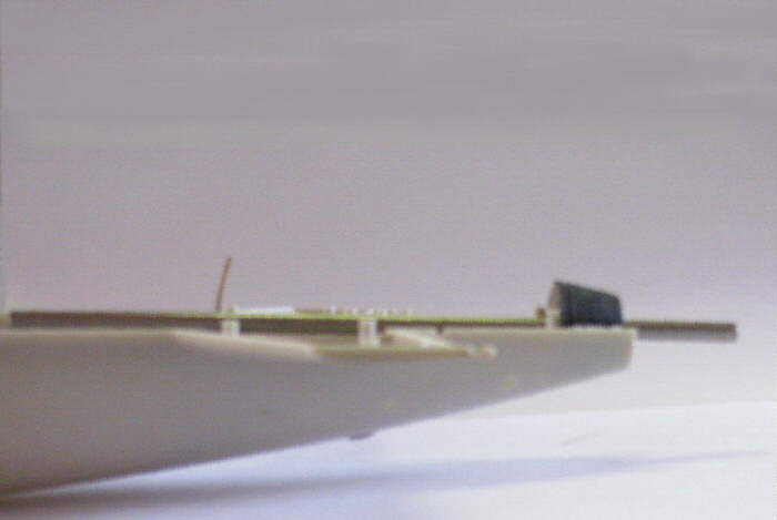
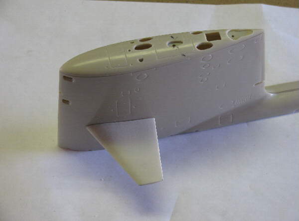
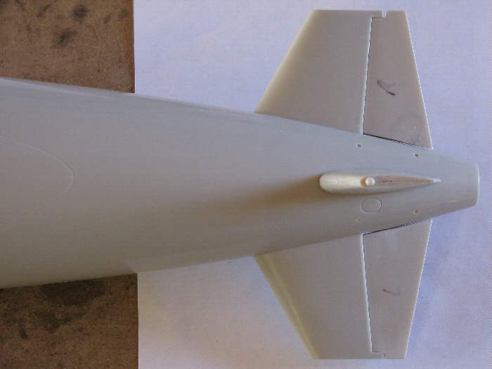
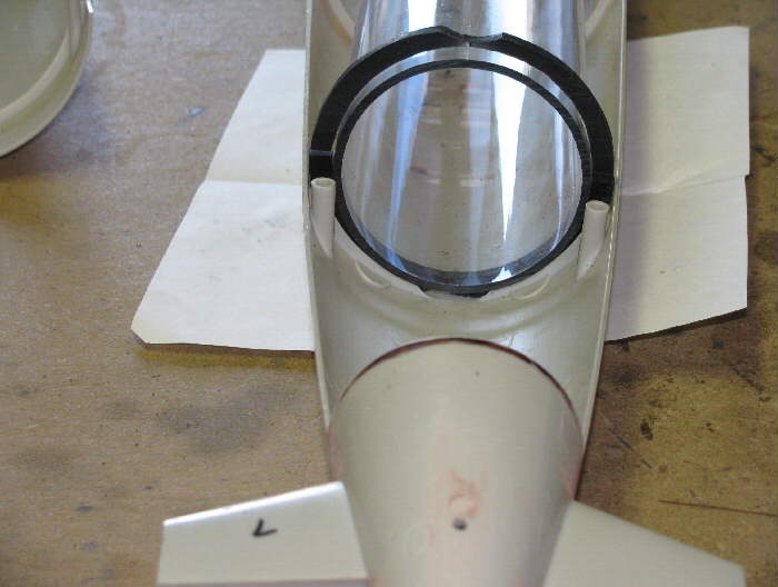
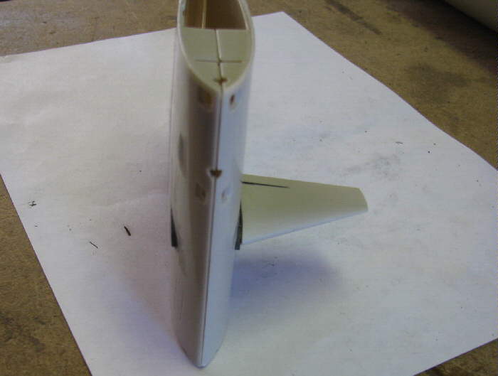
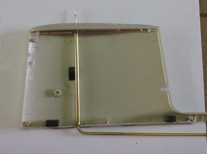
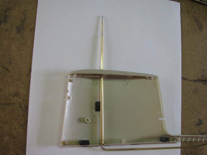
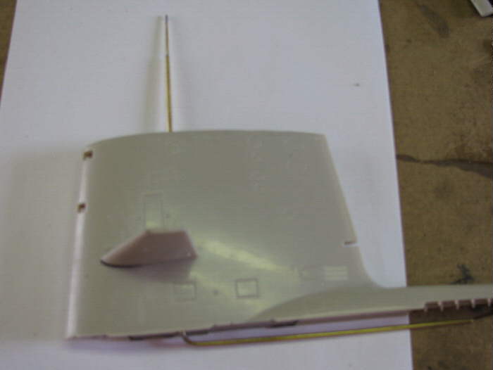
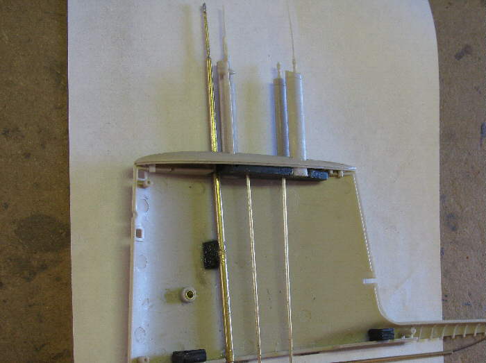
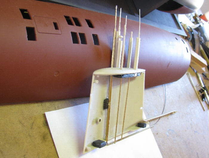
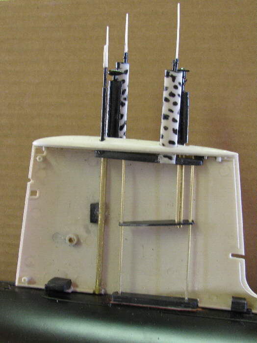
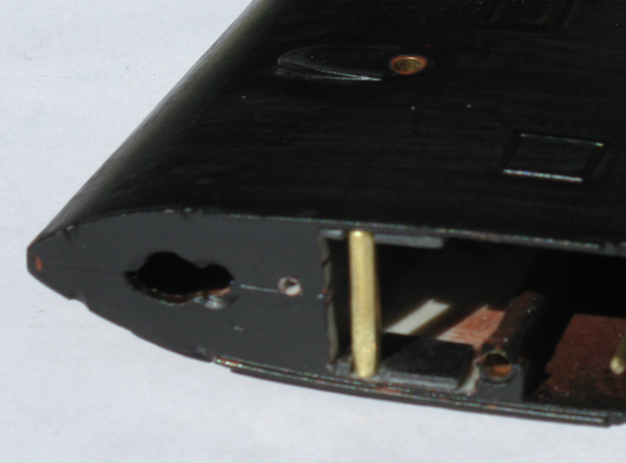
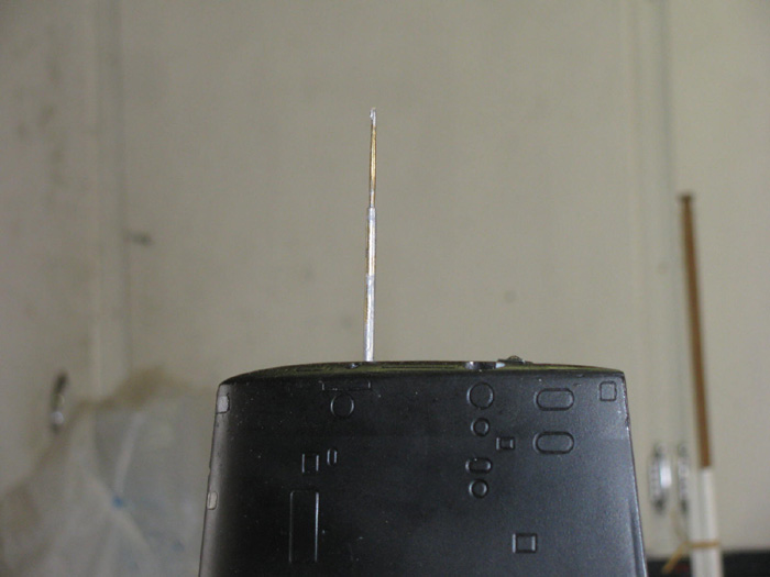
Here's a look at the top of the sail with mast raised.
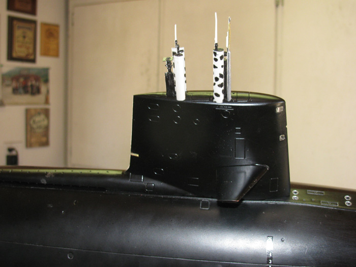 |
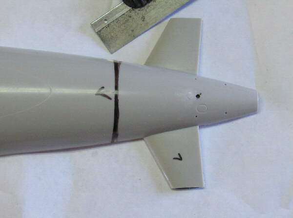
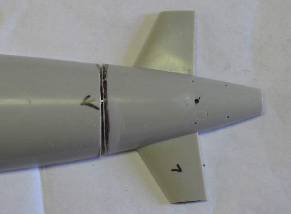
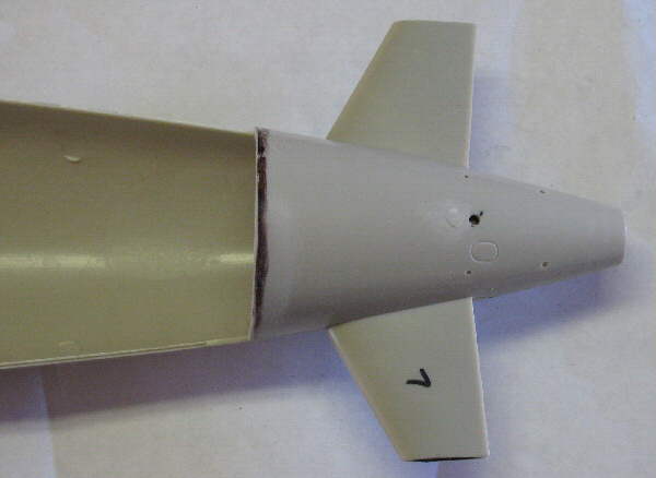
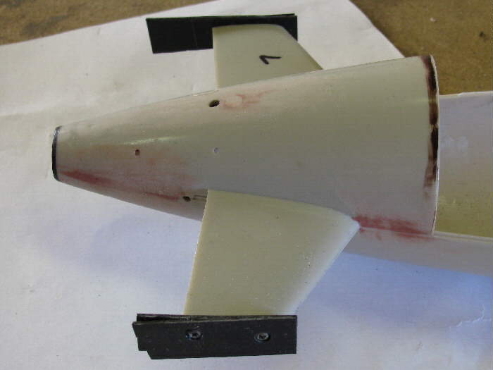
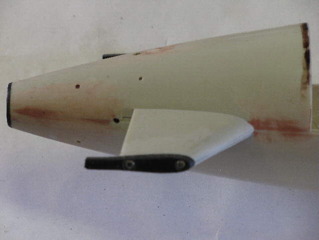
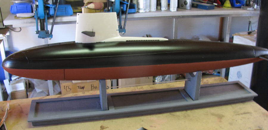
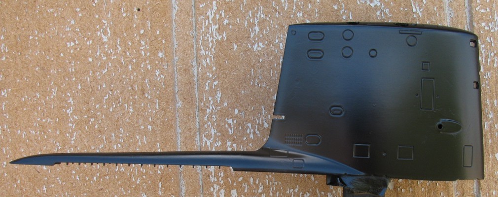
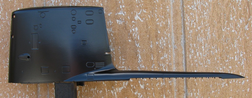
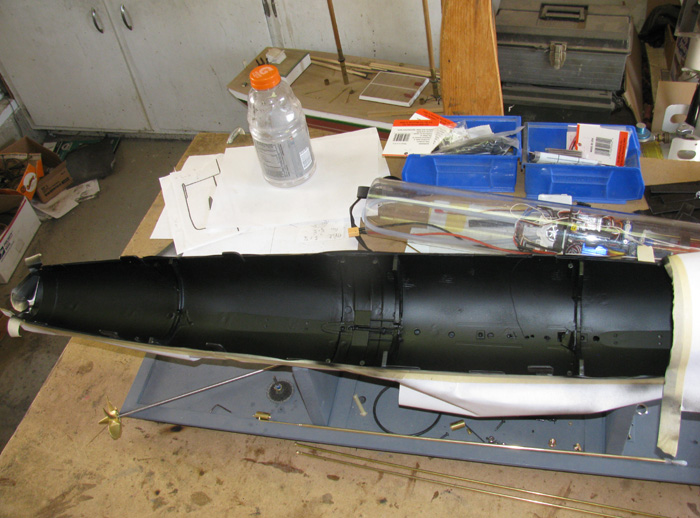
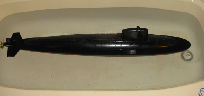
Boat with draft marks on.
The lower rear part of the hull has not been buffed out yet.
The spots on the upper hull aft of the exhaust housing are sunlight
coming through ceiling vent. 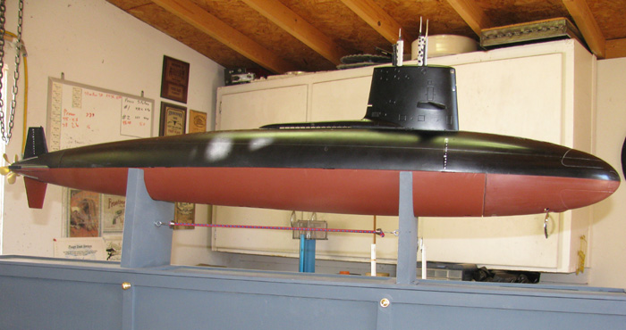 |
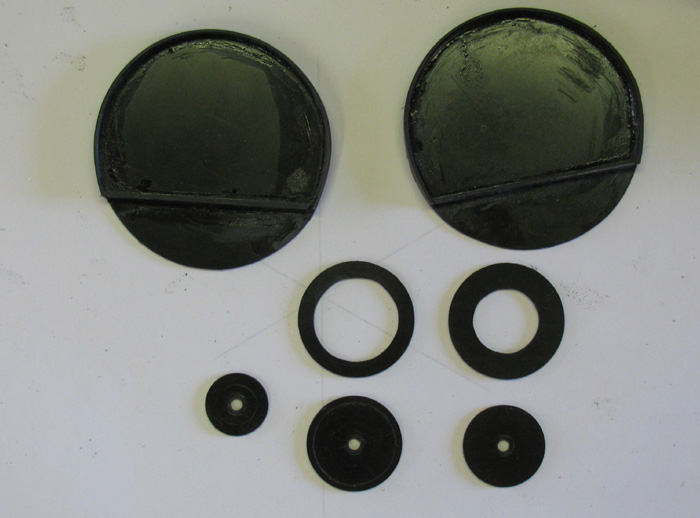
Control Rod Seals
I spent some time over the weekend looking all over the net for 1/8"
shaft seals.
Seems like everyone who made them in the past have given up on them.
Also while looking for parts I went through a box that had parts from
my first submarine. 1988-9.
I found three old seals. Back then we had to make our own seals.
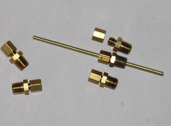
Basically it's a 1/8" ferrule tubing to 3/8" pipe brass fitting.
I had drilled out the pipe end to 1/8" so a brass rod would move through
it smoothly.
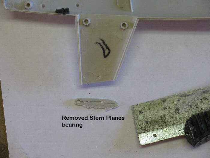
You can see the original seal below.
It has the brass rod going through it.
Old seal assembly from 1988-9 from my first working submarine.
The other four fitting were bought this morning while in town.
I found them at NAPA auto parts. Auto Zone has them but call them special
Edelebrock fitting and want your first born for them.
The fittings come with a brass barrel which I gave back the store.
I don't need them.
 |
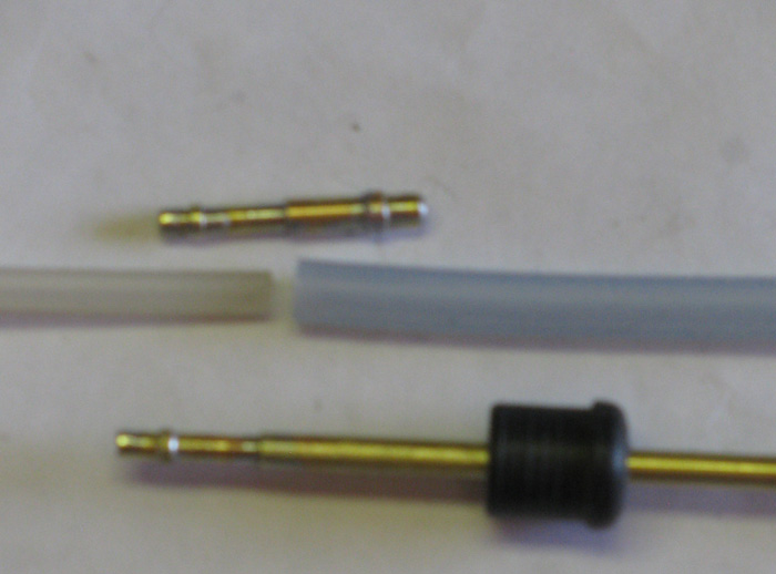
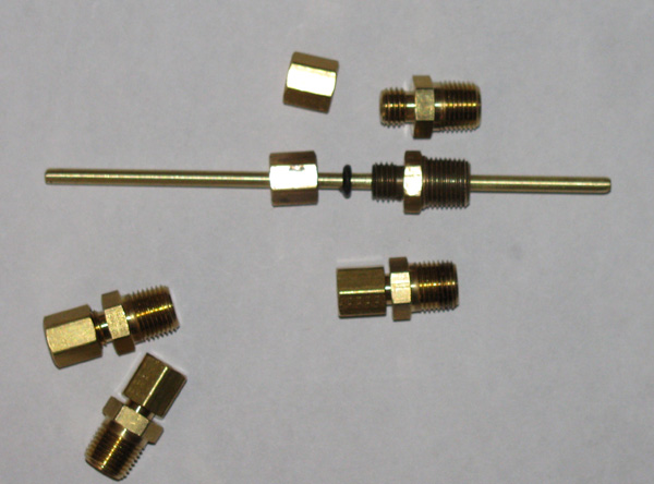
This photos shows the old seal assembly parts.
Three parts.
The two brass fitting parts and a single o-ring.
Only modification made back then was to drill out the 3/8" pipe side
to accept the brass rod.
Also used as a guide and bearing for the rod.
 |
This image shows the end of the fittings that needs to be drill.
It's not much.
Second fitting from right is the old fitting that was drilled out. 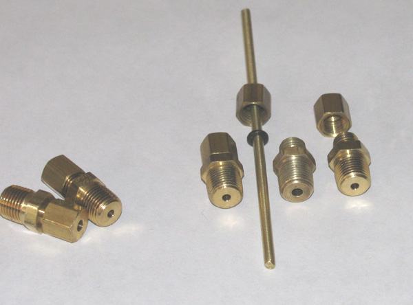 |
Once you put them in your end cap, you adjust them finger tight and
then check for leaks.
You can tighten or loosen as needed.
Once you have it adjusted, you put a single small drop of glue on the
nut and body of the fitting.
Should you need to replace the o-ring or re adjust the pressure on
the o-ring, you just cut the glue or twist it loose.
Now for some technical information.
I dug the seal assembly out yesterday.
It has been in the box of parts since 1991.
The o-ring still has silicone grease on it.
I can find no crack on the o-ring.
The o-ring is still soft with pressure by fingers.
The rod still slides back and forth easily with no hesitation.
I can not blow air through the seal past the rod.
I think the seal could be used today without worrying about it.
My plan is to modify the new brass fitting by taking off the 3/8" pipe
threads.
Drill holes in my end cap just deep enough to silicone glue the assemble
in to the cap.
This will reduce the weigh some and the hole needed will be much smaller.
I paid $2.40 each for the new fittings at NAPA.
I check when I got home if I could get them cheaper else where.
Well McMaster-Carr
has them for $1.70 each.
Don't know about shipping costs.
I don't mind spending a little more to help local business.
End Caps
Pumps ..... have been located.
I have them in hand.
Another poor man's solution to a problem.
I have for some time now, looked in to finding shaft connectors.
1/8" by 1/8".
What I found was fine but at $4.99 each plus 4.75 shipping, I wasn't
interested.
None of the hobby shops I get to have them in stock.
I have thought about get some brass rod and trying to make my own.
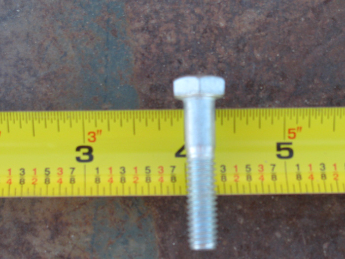
Even found a big brass bolt in my tool shed that I could use.
But there is always something that stops me.
This time I don't have a tap for the set screws.
To buy one would be as much if not more then the $10 connector.
This morning I was laying out all the electronics on the work bench
to see what I have and don't have so I can start building an equipment
tray.
While I was moving things out of the way, I saw an old sail plane control
horn.
It's made from two wheel collars and two lengths of 1/8" brass rod.
They are soldered together.
But I thought the solider wouldn't hold up with starting and stopping
of a high torque motor.
After months of putting this issue off, the light came on.
Again the solution is so simple, I didn't think about it until now.
The solution will take 5 parts and I don't have to make but one.
Two others need modifying but I can drill a couple of holes.
So I got the parts and did the modifications.
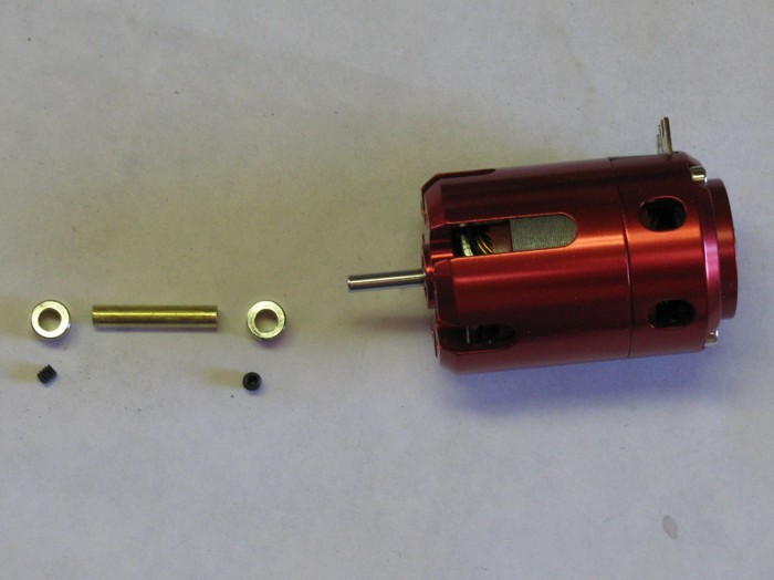
And here it is for everyone to see.
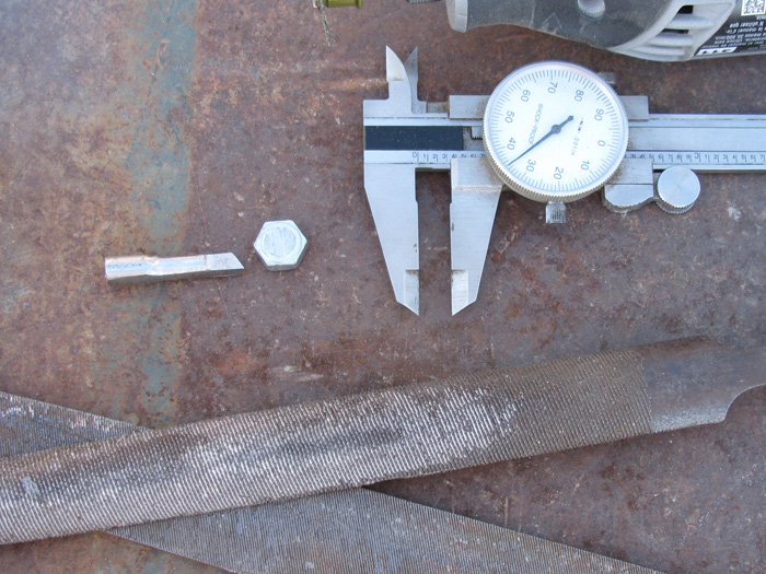
| Found and cut a 3/4" length of brass tubing the 1/8" shafts will go
in to. (This is my standard control shaft bearing tubing.
I found two 1/8" wheel collars and two set screws.
Count them .... That's 5 parts.
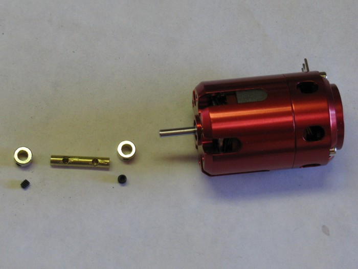
Then I drilled the wheel collars holes to accept the tubing.
 |
Next I drilled two holes in the tubing so the set screws will go through
the tubing to the shafts.
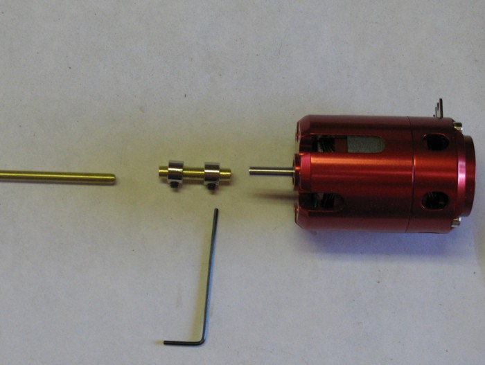
 |
Clean up the inside of the wheel collars with a small round file to
debur so the tubing will slip through. With some effort. Tight fit.
Put the set screws in the wheel collars.
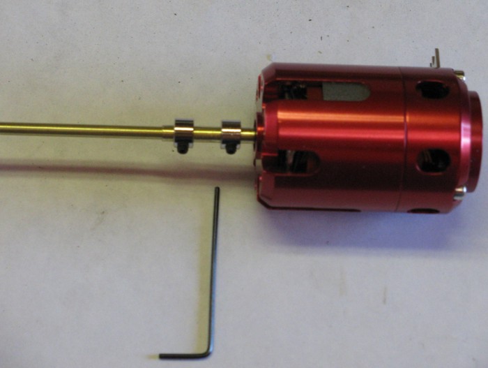
 |
Slip the connector assembly on to the motor shaft then tested the other
end with a piece of 1/8" brass rod. (I need to get some stainless steel
rod for this)
I now have a shaft connector made from spare parts.
It took me 15 minutes.
I thought about soldering the tubing to the wheel collars but then thought
I do not want to have to go through balancing the connector. I have two
razor blades mounted in a block of wood but why go to all that trouble.
If the set screw goes through the tubing to the shaft the tubing is
not going to slip or turn.
So this is how I made my poor man's shaft connector. |
Electronics
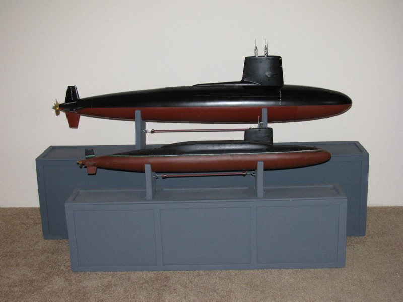
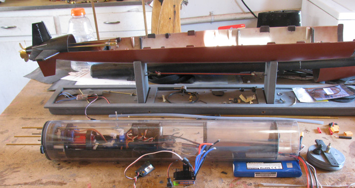
Just something to look at ........ 1/72 Skipjack behind 1/144 George
Washington
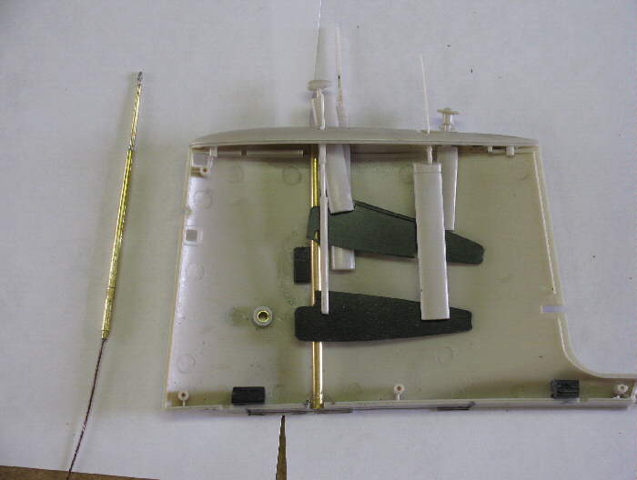
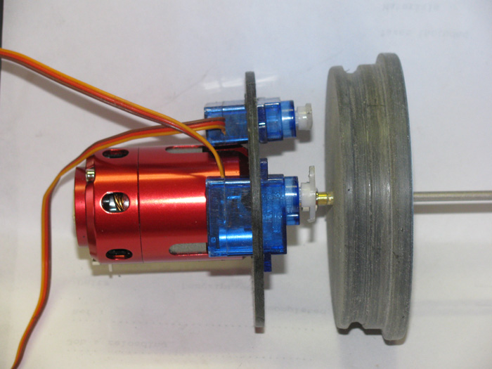
What we are looking at here is the motor mount bulkhead and the two
servos that will operate the Mast Gizmo and a periscope.
 |
The motor with it's poor man's shaft connector
propeller shaft going through end cap bearing
two servos
It's a start on the equipment for the Skipjack.
 |
Time to make the seal retainer.
Some time back, there was a discussion about trying to imbed the seals
in to the end cap.
Was it practical?
Well, I decided to give it a try.
I have materials to make another end cap if I have to but I/we) need
to know it this will work and how much trouble it is to do.
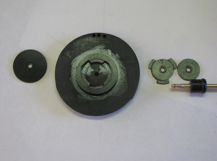
Here is my end cap with the seal recesses in the end cap.
I explained how I made the seal recesses cutters and cut the end caps
on another web page. [url=http://www.cliffhangershideout.com/cutter/cutter-seals.html]Cutter
for seals[/url]
The piece on the right side of the photo is the 3 pieces of 1/16" plastic
cemented together the other day.
The piece is already shaped but what I did was cut three pieces of oversized
plastic that covered the end cap just below the motor seal. I used the
end cap to trace the circle and then free hand the two tabs on the sizes.
I roughed shaped the pieces with the drill sander disk. Then I used
the small Dremel drum. Finally I used several different files to finish
up the shaping.
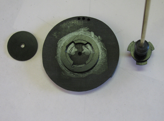
While doing he shaping I thought about the air bubbles that might be
trapped by the plastic plate. So, I beveled the bottom edge at 45 degrees
to the cap. That should stop any bubbles.
Before I shaped the plastic I drilled an 1/8" hole where the motor shaft
will go through.
I place an 1/8" brass rod through the end cap and the plastic piece
to hold everything centered.
I then drilled an 1/8" hole using the top hole (rudder control rod)
for a second brass rod.
Then I drilled the other needed through holes.
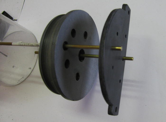
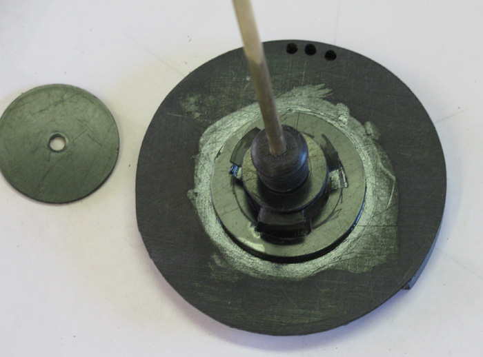
Here the end cap is in my 3" piece of cylinder tubing with the seal
retainer slipped on.
The two side tabs are for long brass tubes with bolts that will hold
the front and rear end caps on should there be pressure build up in the
cylinder that might displace the end caps. Tim had this problem. I thought
I might try to avoid that problem now.
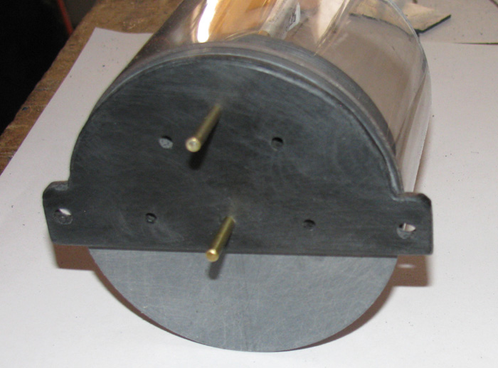 |
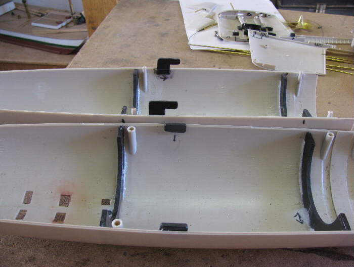
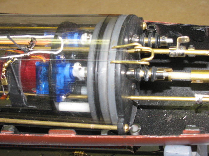
Control Rods
The cylinder is sitting in place using the hull frame and the end cap
seal retainer as my guide to measure the control rods Coming out of the
end cap are 1/8" brass tubing. On the inside of the cylinder the 1/8" brass
tubing has 1/16" brass rod soldiered in to it. The 1/16" brass rods are
fitted with nylon clevies that fit tot he servo control horns. The rudder
and stern planes have the same 1/16" brass rod with the nylon clevies.
A 1/8" brass wheel collar is soldiered to the end of the 1/16" brass rod
and slips over the 1/8" tubing for adjusting.
In the photo you can see the two winch drums in place.
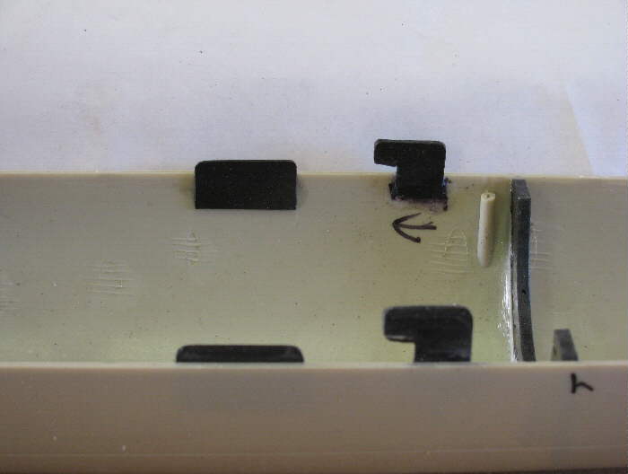
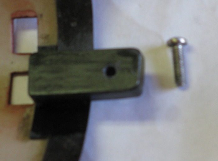
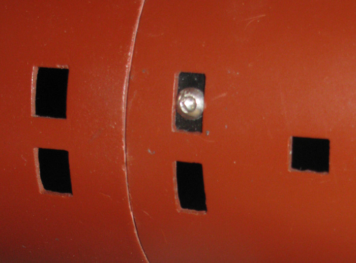
Top and Bottom hull safety bolt and lower tab.
The tab is threaded.
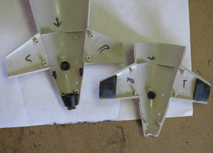
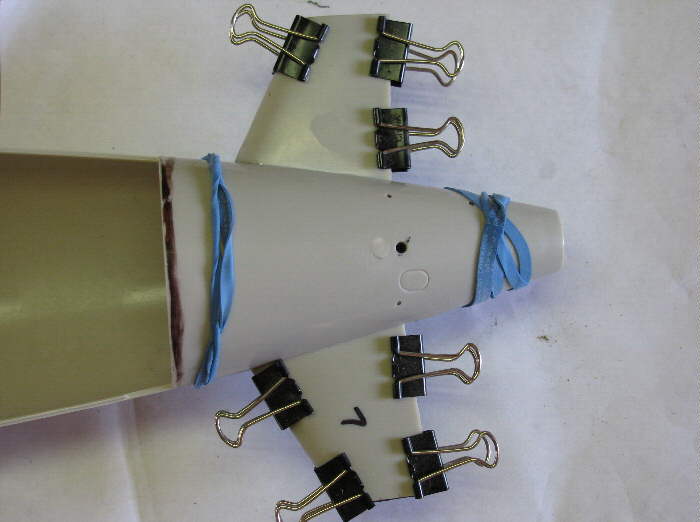
There is a plastic block glued in place behind one flood port.
This block is 3/16" thick and sanded to make the curve fit the hull
diameter.
The block is drilled so the bolt goes through with a little bit of
room to move when aligning with t he up hull tab.
The bolt is a stainless steel allen bolt. IT was 1" long then I cut
it off to what was needed.
The head of the bolt does not stick out beyond the hull.
I will paint it black at some point to hide it.
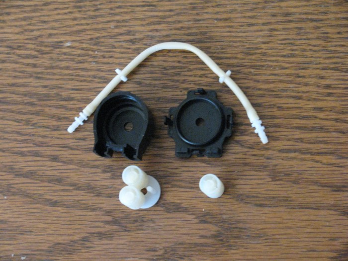
Started the plumbing from the ballast pump to the ballast balloon and
to the rear end cap.
Here are the fittings I made from brass tubing.
The tubing will slip over the tubing and there is a ring that is one
size larger that will stop the twisted wire that will hold the silicone
tubing in place.
Top one is from pump on right to intake tubing on left.
I also made a connector that will go from the pump to the balloon. The
plastic pieces is so the balloon fits tight and when the tie wire is in
place the balloon can't slip off the plastic.
The brass tubing extends past the plastic piece at this point because
I don't know the final length just yet.
The plastic piece is not yet glued on to the brass tubing so I can
slip it to it's final position.
Ballast balloon Containment Tank
After several days of trying to find a glue that would stick to various
plastic bottles so I could use the screw on tops, my efforts ended in failure.
No one of the glues or cements or bonders I have even thought about holding
two parts together. I didn't even have to put any force on the parts. Just
blowing on them caused them to fall apart.
So, today I decided to solve this issue from scratch.
I am going to make a bayonet twist lock.
Three lugs.
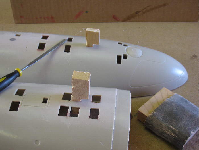
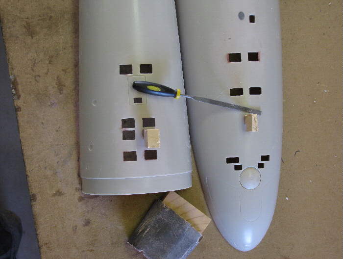
Cut a few pieces of sheet plastic and made a few pencil drawings.
Cut the plastic sheet in to squares, then I started turning them in
to circles.
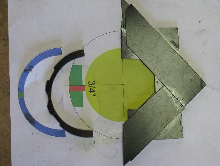
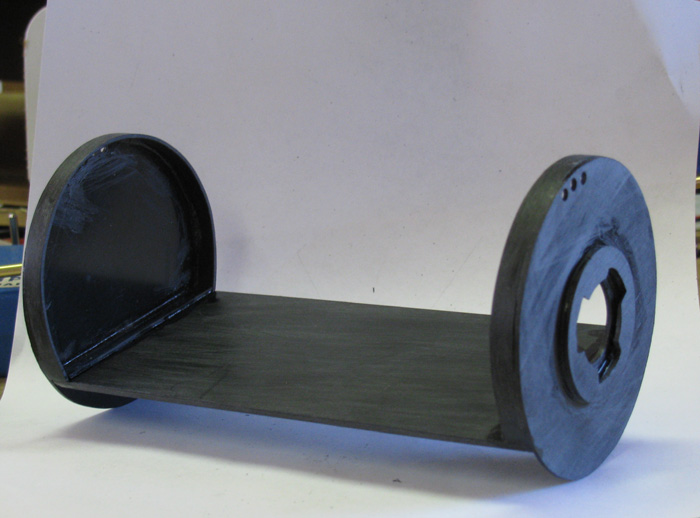
The photo below shows the containment tank ends.
The bottom of the tank will be flat so the battery can be slid under
the containment tank.
Will also be running power wires under the tank.
The five pieces will become a what I need.
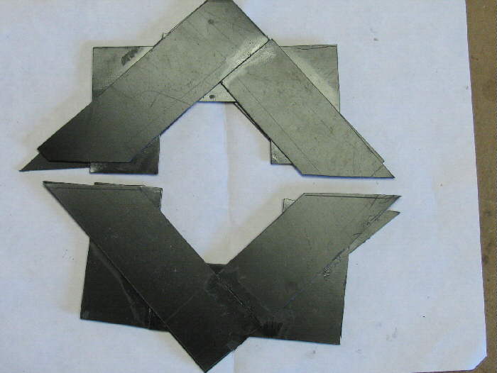
Access in to the Containment Tank to change the ballast balloon when
needed.
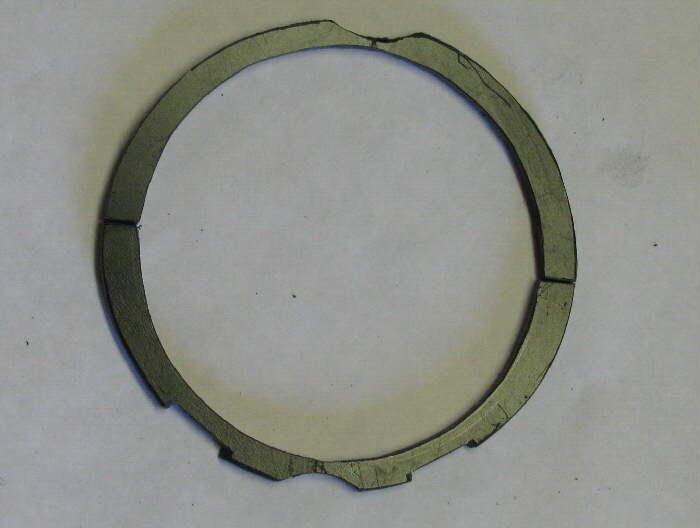
I have made the three lug capture ring and mounted on the Containment
tank end.
Actually there are two rings.
In the above photo, the thin ring is put on the cap first then the
lug ring, allowing room for the center lug piece to turn and engage the
lugs.
The center of the cap has not been removed yet because I am using the
small hole in the center to keep everything in alignment as I go.
Here you can see the engagement lug on the brass tube.
Nothing is glues in place yet.
Still more fitting and making of parts before I can do that.
The circle on the left goes on last and will make the water resistant
seal , should the balloon break the water should stay in the containment
tank.
There are three 1/8" hole at the top edge of both end caps so the tank
can vent pressure when the balloon is filled and drained.
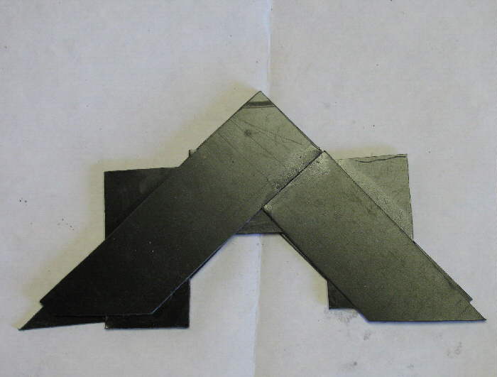
Here the center lugs are sitting just above the lower lugs.
And before anyone points it out, Yes, the center lug is on backwards
to show how it will fit.
The plastic piece at the top of the stack is where the balloon will
be attached and will be on the other side of the lug so it goes inside
the containment tank.
It was easier to photograph this way.
I should get everything assembled tomorrow and have a Ballast Balloon
water Containment Tank.
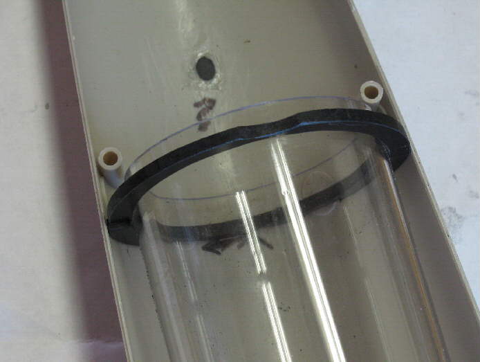
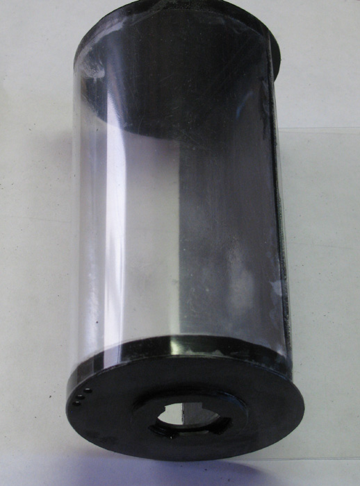
Here is the bayonet three lug on the end of the tank.
I have assembled the tank end caps and bottom.
Still need to wrap the .02" clear styrene plastic sheet around the tank
frame and trim the excess off.
Currently letting it sit and cure before I start putting an stress
on while covering.
After covering the tank will become rigged.
I will need to cut a notch on each end where the battery will slid
under the tank bottom sheet.
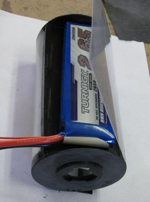
There is room for a 2600mh LiPo
Wrapping the clear styrene around the containment tank end caps.
The clear plastic still needs to be trimmed flush with the tank bottom.
The battery sitting in place making sure I have room.
More than enough room for battery and wiring that will go under the
containment tank.
Ballast Tank Containment tank slid in to the cylinder.
Battery will sit under the BCT.
I decided to have the water hose from the pump enter at the front.
This way when I open the cylinder at the front, I can disconnect the
hose by turning the bayonet lug cap.
Pull the ballast balloon out and then I can each in and pull the BCT
out with just one finger.
Also considered putting the BCT hose at the rear but then I would have
to make sure the hose from the pump didn't interfere with the out runner
pump motor. (Out Runner motor = the outside of the motor turns instead
of the inside)
I was surprised when that happened ! ! !
I was holding it in my fingers when I tested it.
Also, I would need to open the rear cap to push the BCT out the front
or rear.
Too much trouble.
Assembling and Wiring....
Here the Electronics tray has been wired.
The Speed controller and Fail Safe circuit are not installed yet.
That's next after lunch.
Then the main power wires need to be connected to the plugs and Off/On
switch in the front end cap.
The new 10A speed controller arrived.
I will wire it in and test it.
The 10A was the original for this build but the one I have didn't work.
No reverse and the Fail Safe would activate.
If the 10A does not work again, I will temporally place the 30A in.
It works.
Just realized.
The size of the 10A Speed Control compared to the 30A speed controller
can be seen in the above photo.
The 30A and Fail Safe are in front of the cylinder.
The 10A speed Controller is sitting under the stern of the boat. 3
blue wires and the battery wire plug.
The 10A speed controller is no bigger than the Fail Safe circuit board.
Should be able to complete the wiring today and tested.
Then I can grease up and install all 5 O-ring and the 1 cup seal in
to the rear end cap.
Water Testing.
Well, I tested the new 10A Speed Controller.
It works.
Soldered every thing in and .... WHAT? .... the 10A speed Controller
failed again.
It runs in both directions but it lags the Tx stick control by 2 seconds
or more.
The motor runs very slow (it cogs) and then stops after a few seconds.
I though maybe the battery needed charging.
Charged it up to full.
No change in the pump motor.
So, I will be removing the 10A Speed Control and putting the 30A Speed
Control in.
Fortunately, I have room for it and I built a platform for the 30A
Speed Controller when the first one did not work.
I didn't plan on the new SC showing up in time.
So, first thing this morning, I will remove the 10A and put the 30A
in.
Maybe 15 or 20 minutes for the redo.
Changed out the Speed Controller.
Motor failed again.
So, I changed out the motor.
Ah, now it all works.
While I had every thing apart on the bench, I removed the 30A speed
Controller and put the 10A SC in.
It works too.
So my ballast tank problems was the motor and not the Speed Controllers.
Disassembled all the ballast system parts.
Did this because during the testing the parts where not on the electronics
tray and wiring needs to go through some holes in the tray to get where
they need to be. So, I started assembling all the parts again and making
sure to slip the shrink tubing over the wires as I went. Got it all back
together and... you guessed it. Testing again.
Everything works.
Okay. Time to move on.
Ballast system.
The water path parts.
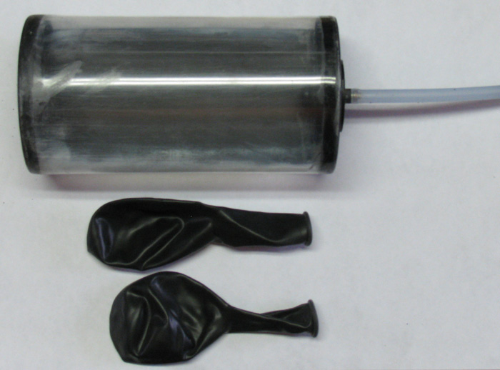
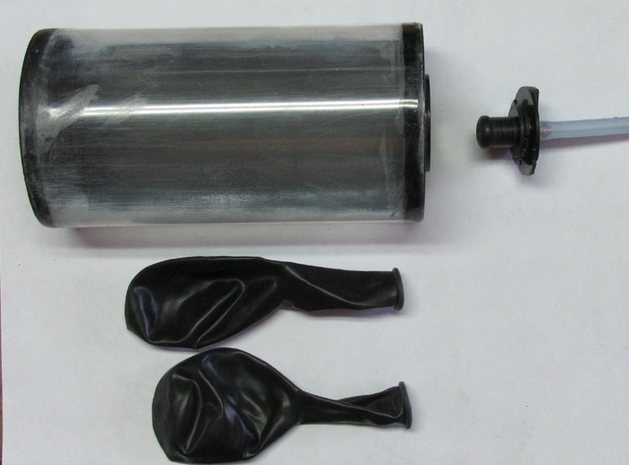
Got the balloons that go inside the Ballast tank containment tank.
Containment tank and balloons.
Here the piece that holds the balloons to the pump line removed from
the containment tank.
This is where the bayonet lugs come in to play.
Putting one balloon inside the other.
This is a safety item recommended by Tim.
I'm basically copying Tim's build so two balloons it is.
Balloons mounted to the fitting on the bayonet fitting.
By making the bayonet lug cap allows me to get the balloon in to the
containment tank.
1/3 turn and the piece is locked in to the containment tank.
This photo is with the balloon filled with air checking for leaks.
===========================================
Ballast Balloon problems.
During water testing, the ballast balloon filed as it was suppose to.
During emptying, no water was pumped out.
I had to remove the ballast safety tank with ballast balloon inside.
I found the problem.
Second water tested.
There is a leak again.
First I thought it might be any of the many o-rings.
But with t he ballast balloon full there was positive pressure in the
cylinder.
Need to look else where for the leak.
Opened up cylinder.
Removed end cap and disconnected battery wires and switch.
Removed battery.
Slipped electronics tray out rear of cylinder along with the ballast
safety tank with full ballast balloon.
I looked and did not see water around or near seals.
Let it all sit until dry.
No water seen.
Plugged in battery and turned on Tx & Rx.
Cycled controls and started emptying ballast balloon.
I reversed the motor direction to get the fast for filling and the
slow for emptying.
Water was draining out the rear cap brass tube.
Aft a few seconds I could see water at the pump end of the electronics
tray.
Closer inspection, I found a leak.
The silicone tubing from the rear end cap to the pump has a pin hole
in it.
Under pressure it opens and drips.
Here it is.
==============================
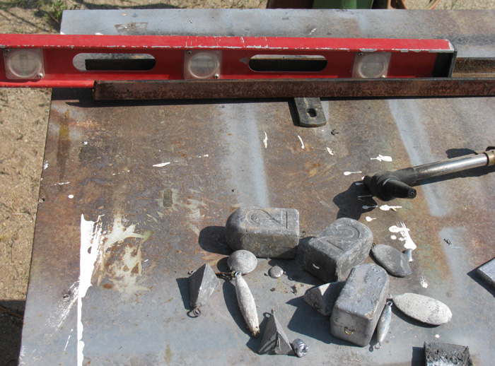
Time to make lead ballast bars.
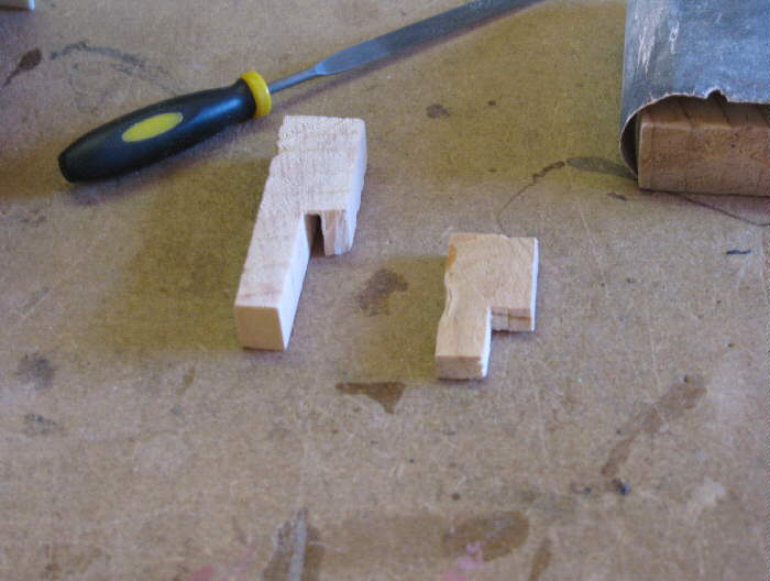
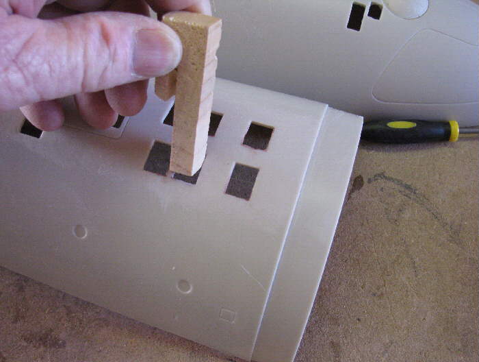
I use a 2" piece of steel channel iron.
I cut wood blocks that fit inside the well tight enough that it requires
a couple of traps with a hammer to set the blocks all the way down in the
channel.
Here, you can see I have leveled the table.
The table has been sitting in this location some 30+ years and
has built a lot of projects.
Over time the table legs even with 2"x6" blocks under the legs has
sunk on once side.
The table has a 2.5" slope over 30" width.
Foreground has lead sinkers and scrape that I will be using.
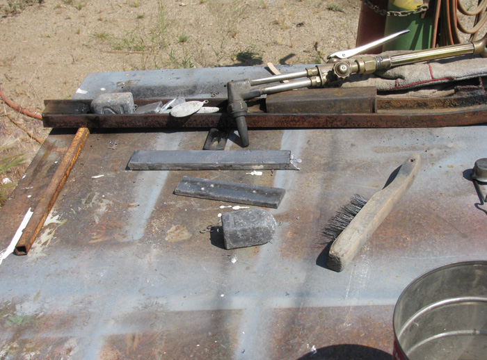
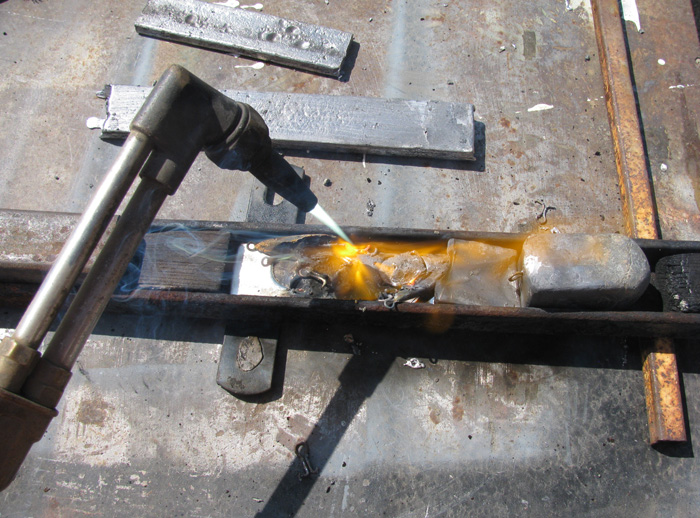
Ready to start melting the lead in to the mold.
The process has begun.
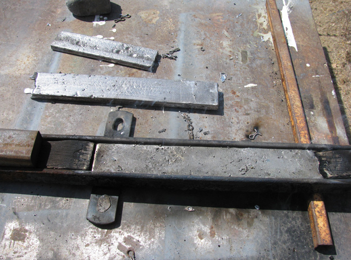
Three bars completed.
The top one is 1/4" thick.
The Middle one is 3/8" thick.
The one in the mold, I'm not sure but it looks like it's more than
3/8" but not 1/2" thick.
Once I figure the needed weight during trimming, I will cut the bars
in pairs.
I will cut them so they fit between the plastic ribs in the hull..
I use a band saw and bee was to cut the lead.
After I get the length correct, I will using a big bench vise, hammer
them with a curve to fit the hull shape.
Doesn't need to be perfect because the silicone glue will fill the
gaps.
Might even fill enough, I won't need to bend them.
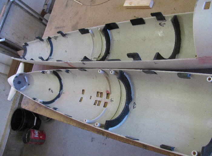
While waiting for the lead ballast bars to cool off enough to handle,
I took the time to mask off and painted the inside of the hull(s). Both
the top and bottom.
Photo is the top half or the hull.
Isn't that pretty.
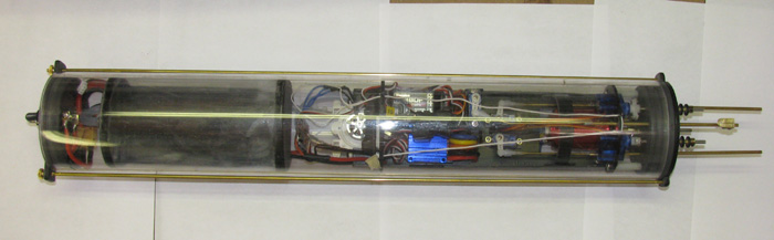
Completed assembled Cylinder!
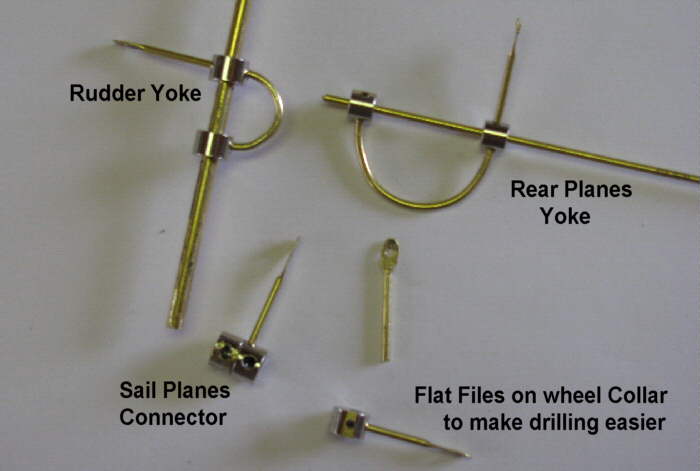
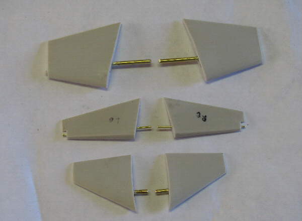
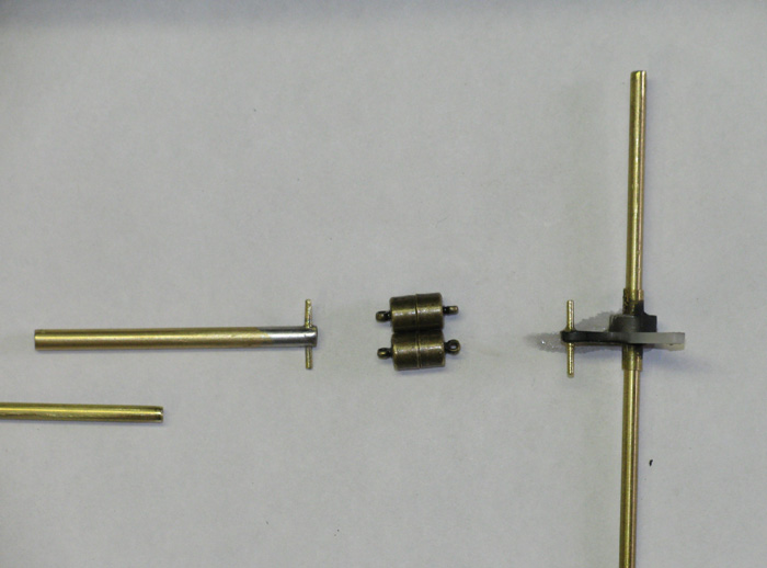
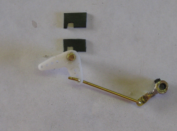
Sail Planes Control Rod Connector
On Left is control rod end that go on push rod from servo.
At center are two magnets. (4 pieces)
On right is the sail planes lower control horn.
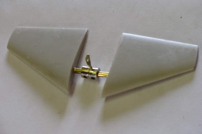
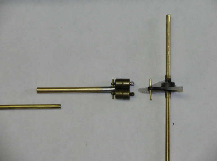
Magnets mounted on Control rod end.
These will be mounts solid in a straight line with the control rod.
The magnets that go on the control horn will swivel to self align to
the control rod magnets.
The long control rod will be held on top of the cylinder by a small
length of velcro strap with a loop in to allow it to move up and down to
attach to the control horn magnets without friction.
Sail Planes connecting Rod .... completed and tested .... several times
to get the final length.
Water Testing ........ No Leaks found.
Cylinder was on surface.
Operated all the controls.
Removed from water to inspect thoroughly.
Looked for leaks.
Back in the water and left for 30 minutes on surface.
Checking often, just in case.
Operating controls.
Removed from water and found no leaking.
Back in the water and fill ballast balloon half way.
Cylinder lowered in the water as expected.
Removed from water and checked for leaks.
Still good.
Back in the water to fill ballast balloon more.
At about 3/4 full the horrible sound of the pinion gear slipping on
the motor shaft.
Checking to make sure this is what was happening, the pump housing
is clear on one side, to check is just a matter of rolling the cylinder
over and looking in to the pump housing.
Sure enough, the pinion gear is slipping.
Decided to continue leak test by weighting down the cylinder so it
sat on the bottom and completely submerged.
Left there another 30 minutes.
No Leaks.
Home made cylinder and end caps passed the test.
Now I need to open up the cylinder and remove the ballast containment
tank with the ballast balloon inside.
Once out of the cylinder, I can drain the ballast balloon.
Then I can open the other end of the cylinder and slide out the electronics
tray.
Remove the pump.
Open up the pump housing and check the pinion gear more closely.
The solution I plane to use is to run the motor and using 100 wet and
dry sand paper, take the shine of the motor shaft.
Then apply a very small drop of water proof glue.
Press the pinion back on and let it sit.
I can do that and reassemble the pump.
Put the ballast system back in.
And seal it up.
Won't run any of the systems so the glue can dry completely with out
me mistakenly operating the pump motor.
With the cylinder sealed up, I can move on to surface trimming to get
the needed lead ballast set and foam.
Then to do submerged trim is just a matter of moving the weigh and
foam around to be the boat level submerged.
Ballast Pump Issue.
I disassembled the pump.
Sanded lightly the shaft.
Glues the pinion on the shaft.
Took some time away from the boat to work on my truck.
Had to fine why the running lights did work.
5 minutes and that problem was solved.
Went to town to get stuff to make lunch to take with tomorrow.
Put pump back on the electronics tray.
Test ran the pump.
Things are good.
Put every thing back in the cylinder and sealed it up.
Put the cylinder in the lower hull.
Hooked all control rods up.
Place the top hull on the lower and buttoned it up.
Oh, I did turn on the Tx and then the Rx to make sure all still worked.
I took my best guess on how much ballast lead was going to be needed.
Missed by one short bar too much.
Removed it.
Moved the other bars back about 1" to correct for surface level.
The boat now sits about 1/4" high and level.
The scribed water line is above the surface.
Now the submerged level.
Well, that's going to have to wait.
The pump will not run once water gets in the feed line.
At that point I remember Tim said he changed to a different type of
feed hose.
Of course I knew that because I read it when he posted it.
But I forgot about it.
That was almost a year ago when he tested and came up with is parts
list.
My mistake...I forgot.
There is nothing more I can do about the ballast system tonight for
tomorrow's Fun Run.
So, I removed the battery from the boat and put in on the charger.
Put the Tx on the it's charger.
There is still lots to do on this boat before it's finished.
But, I have a perfectly good surface runner at the moment.
That's how it's going to the event.
Oh wait..... one more things. .....
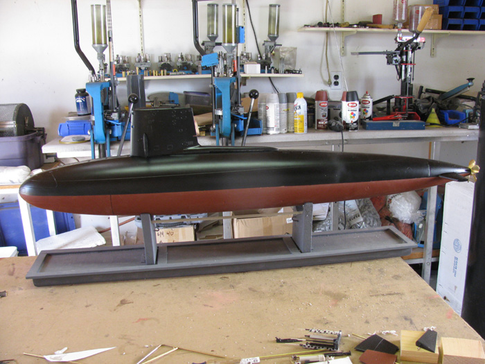
In the water....
Skipjack's first in the water trim test.
The boat was a little heavy and I removed one small ballast block and
hit right where I want to be.... when I start submerged trimming.
I'll problem add the small ballast block back in and add some foam
to trim the submerged level in.
================================
Update. . . . . . . . .
At this point the boat is operational.
I changed the water pump tubing to a larger inside diameter as recommended
by Tim and Matt.
This fixed my pump issues.
----------------------
I am currently back working on t he Mast Gizmo and Periscope Gizmo.
I have made changes to the Mast Gizmo.
It was binding so bad that it would hang up about half way up or when
all the way up, it wouldn't come down without extra effort by touching
the masts with my fingers.
The changes worked.
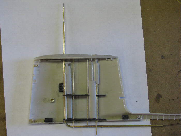
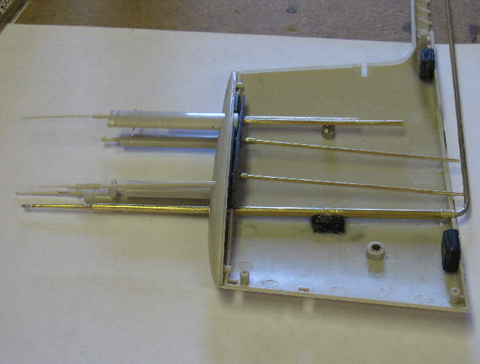
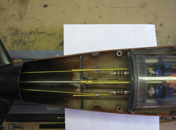
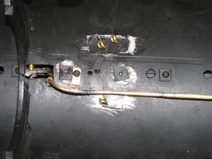
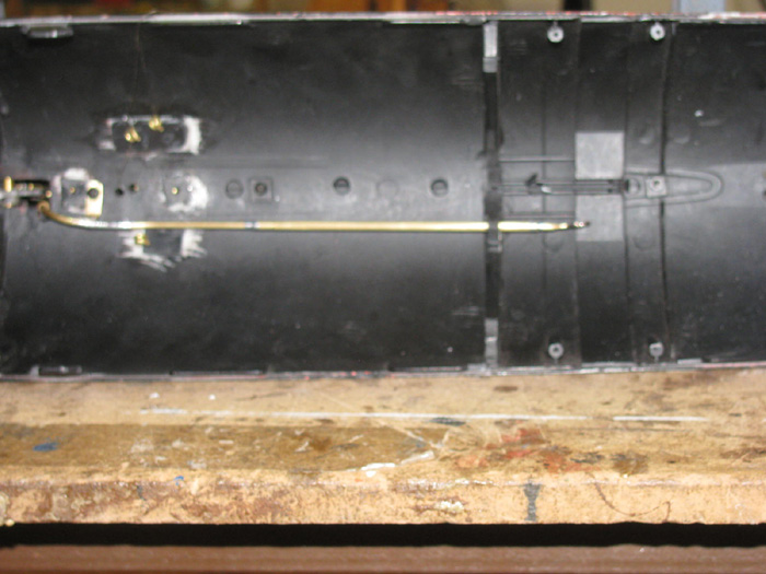
I went on to making the parts needed in the hull to guide the lines
to the winch.
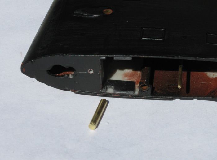
This photo shows the brass rod line guide for the Mast Gizmo.
At the ends of the lines are disconnects and there is a length of elastic
string from one connector to the other via a brass eye at the front of
the cylinder mounted to the front end cap.
This keeps tension on the lines so they don't unwrap from the winch
spool.
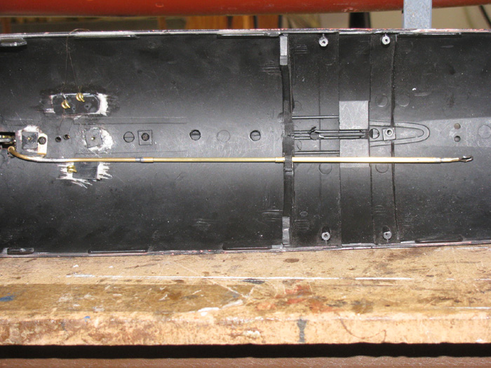
In this photo the two brass eyes at the top guide the lines to the Mast
Gizmo.
One is for up and the other is for down.
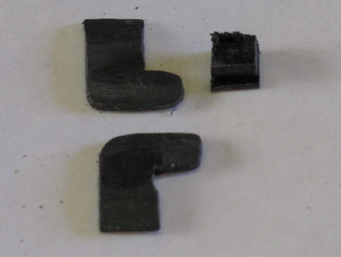
The bent brass is the periscope push cable guide tube.
The tube is made up of two different diameters.
One slips inside the other.
There is a full up stop ring on the left side.
The periscope bottoms out as the stop for full down.
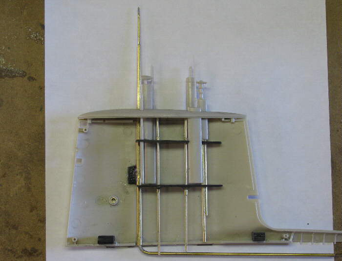
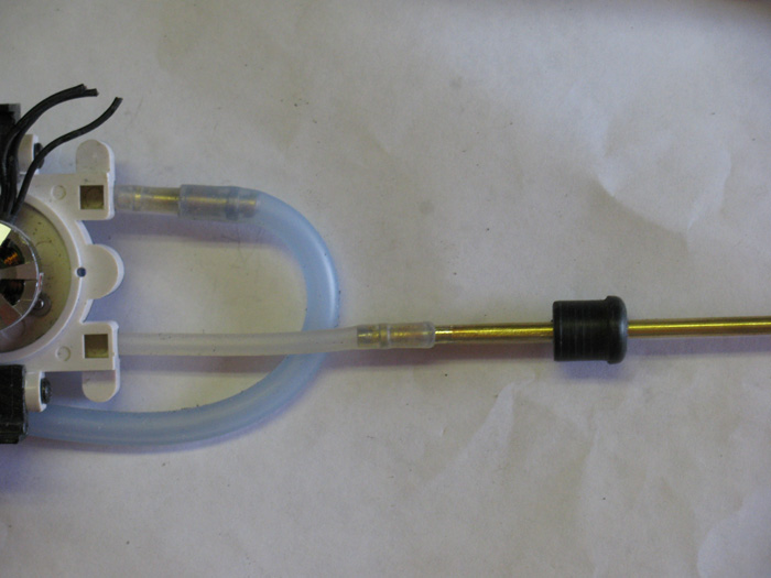
This photo shows the position of the tubes when the periscope is all
the way down.
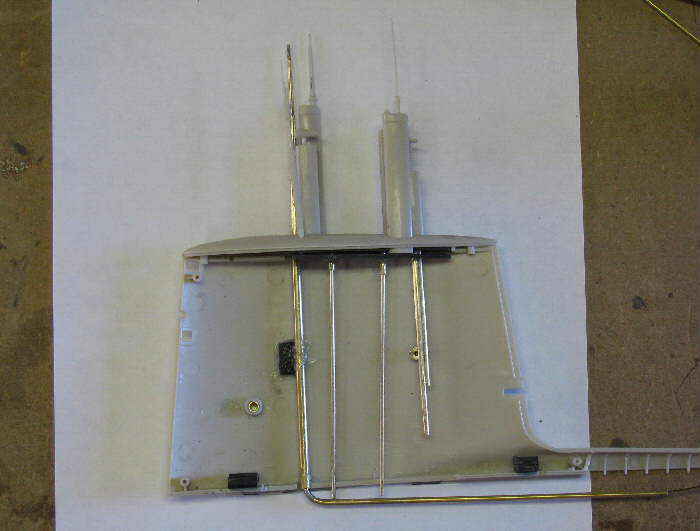
Sorry this photo is blurry.
It does show the tubes position when the periscope is all the way up.
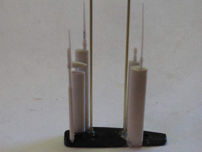
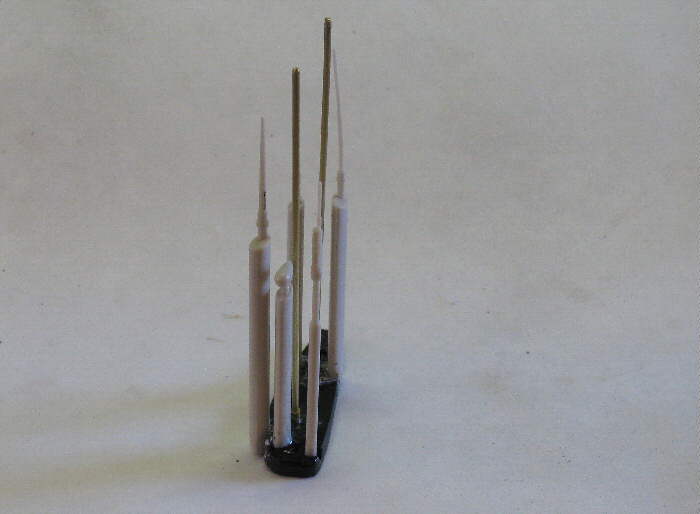
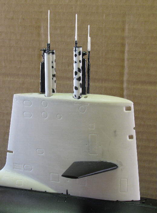
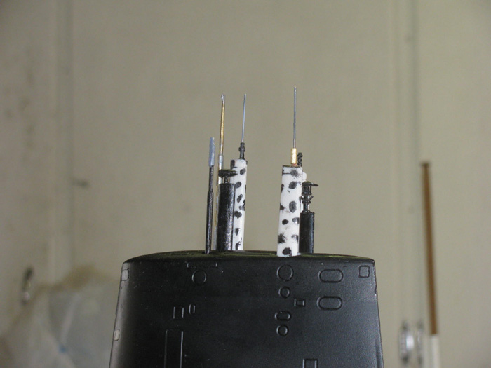
Masts and Periscope all the way up.
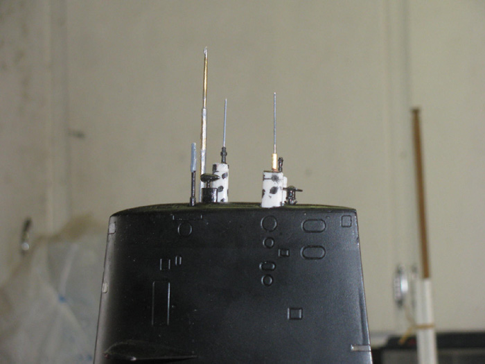
Mast half way up or down.
Your choice.
Mast almost down.
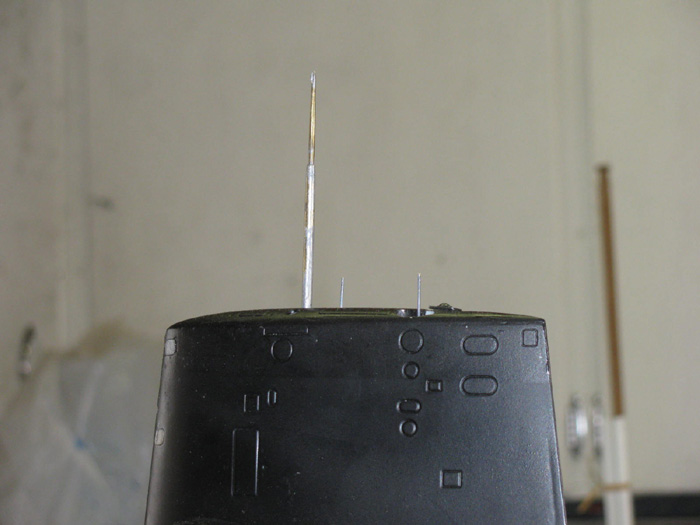
Mast all the way down.
I did get the periscope to go up and down twice.
Then something happened.
The winch did not slip as it was suppose to.
The up line broke.
Not sure what happened.
Have some ideas.
1. I had the lines crossed. Up was down and down was up.
Only thing that should have been effected was the
Tx control knob direction.
2. One of the connectors may have slipped between the cylinder and
one of the frames.
I will have to look in to this issue.
One thing I will do is paint the connectors so I know which pairs mate
up.
Again something to look at. george Washington, Akula II, Skipjack.
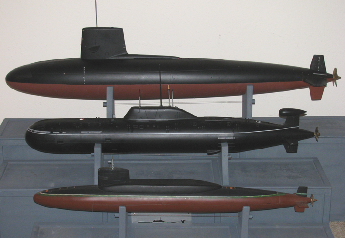
|