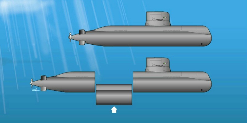
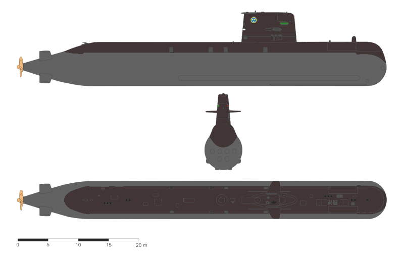
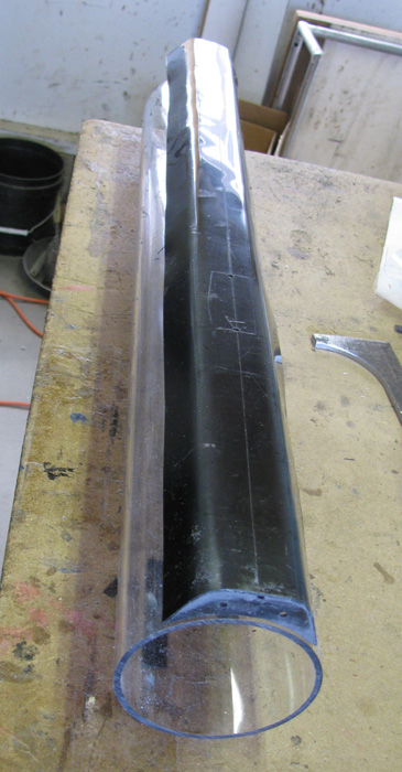
Gotland  A-19 --- Build log by Ralph --- SSBN 598
  A-17 class
  A-19 class
January 2014
I have been collecting parts for this and two other projects. 

First things first. I have over the last few months looked at building this boat trying to decide what scale to build. We knew a couple of years back that this boat would be an odd scale because we were going to try and use available tubing for the main hull. We talked about Polycarbonate and electrical PVC conduit to try and keep the overall costs down. I looked at PVC tubing and found that it was much cheaper but I had to buy 10' to get the 26" for the main hull part. While looking at PVC, I also found that because of the way stores rack it, most if not all had a long sweeping curve that would show in a short 26" piece. This was not acceptable. I have in hand a couple of pieces of Polycarbonate that are for a 1/72 Skipjack. Each is 3.5" in diameter and 24" long.

The PVC, I was looking at had an outside diameter of 4.5" (43.93" overall boat) and the Polycarbonate I have has an outside diameter of 3.5" (34.22" overall boat) I finally decided to go with the Polycarbonate tube. 

4.5" would give a scale of 1/54.15.
3.5" would give a scale of 1/69.50.

For those of you that wanted 1/72 scale to match you fleet, 1/69.50 will be 1.19" longer and .12" wider than 1/72 scale. Very close.

While researching photos, I decided to ask for some basic exterior drawings from Kuchum Ins, Sweden. If your are not familiar with this name, they are the builder of the real boats. 4 days later, I received 2 drawings and an artist interior drawing. The nice thing about the drawings are that they have dimensions and locations of the major items on the hull. In millimeters. I built a spread sheet to do all the converting for me. Millimeters, to feet, to inches to work from. 
 

Here is one of the drawings I received from Kuchum Inc. I will be working from this drawing and my spread sheet. 
 
 
Items I have to scratch build:
Bow section, Stern section, Deck, Sail, Control surfaces, Propellor, Side sonar and Bottoming rails. And then the water tight cylinder interior. (think I found a brass propeller that will work. May be off 1.76 mm OA or .88 mm in radius. 

These items are not going to be hard to build. The issue is to build them and document the process so anyone who wants to duplicate the build ... can. As I go along, I will have to decide if I want to build using Lost Foam or make molds to make more parts. I have only made two molds ... ever. I didn't not like the results and never did it again. 

Today it starts. April 28, 2014
This build will be done in stages.  I have broken down the build in to several Project listed below. I may not go in the order of the Projects listed. Breaking down the build in to smaller projects helps me get things done. Once all the smaller projects are completed then assembly of the complete build can take place.

I am in the middle of building a 1/72 scale Skipjack. The Skipjack is the test build for this one. 
They both will have the same equipment inside. 

Project 1... I'm going to take on the Tail Cone. 

Looking at a section of the Kuchum drawing, I have all the numbers I need. I have already put in all the numbers from the drawing in to my scaling spread sheet. 
1. Hull diameter which was known is 3.5"
2. Length of tail cone to straight hull is 6.00"
3. Back of Tail Cone to rear of planes is 1.84"
4. Back of Tail Cone to planes pivot is 2.76"
5. Back of Tail Cone to front of planes is 3.32" (to be confirmed)
6. Tail Cone diameter at back is .63"

The cone has straight lines with a curve to meet the straight hull. I have decided to make the Tail Cone out of two layers of 1/16" sheet styrene plastic. 

I do not have a lathe so I will be using a Poor Man's lathe. Drill Press. I will leave some of the long 5/16" bolt sticking out each end. I will cut off the head of the bolt so I can put it in the drill motor chuck. I will drill a 5/16" hole in a steel plate to hold the loose end of the 5/16" bolt to the drill press table. 
 

I will build a wooden pattern to wrap the sheet plastic around. Time to do some cutting and gluing of wooden blocks. All I have is 2.5" wide by 3/4" thick stock. I am going to cut over sized squares and drill a hole through the center. 
All glued together.
I use a long 5/16" bolt as a spindle. I originally said 1/4" but 5/16" is what I had and the propeller shaft bushing is a tight fit.
Poor Man's Lathe
 I roughed in the shape outside on the big table vise with a 4" disk grinder with a sanding disk. What you see is the result of putting the pattern in the drill press and using the disk grinder to get closer to final dimensions. Still a ways to go.
I now have to rig some sort of guide to control the lathe chisel. I tried it free hand but the chisel just follows the highs and lows too easily.

Once I get down to within 1/8" of finish I will make a guide out of wood the shape of the tail cone drawings. I will glue sand paper to the guide to do the finish shaping in small steps. The guide will be made to ride on the 5/16" bolt so I can not over sand the cone's shape.

More on making the tail cone.
Here is a quick recap on what has happened.
This was started in April 2014.
Here is the finished wooden pattern.

I tried bending a single piece of sheet plastic. 
This did not go well.
Even tried heating the plastic sheet and this went well for about 3/4 of the bend then disaster showed up.
So I set the tail cone aside while I worked on other projects.
Now back to the Gotland.

Here is my third attempt.
I needed paper patterns to cut the plastic sheet.

I decided to cover the wooden pattern with layers of clear packing tape.

I marked the tape to make several patterns that I can use to cut the plastic sheet .
I put the pattern back in to the drill press (poorman's lathe) and using an exacto knife, I cut through the tape at the marks. 
After cut all the marks, I removed the pattern from the drill press and made a cut through the tape, large end to small end.
I carefully removed the strips between the marks. 

When I had the three tape patterns removed from the wooden pattern, placed them on pieces of sheet plastic. 
I made two sets of tape patterns. The second set was made with the smallest piece narrower.
Why? Because I am going to make the tail cone out of two layers of sheet plastic and the outside pieces will overlap the seams of the inter pieces. 

Here are the 6 pieces.
Three have been hand shaped in to cones and taped to hold the shape.

I have hand fit the first three pieces over the wooden pattern by sanding the mating edges.
I will get a photo of the three pieces on the wooden pattern once the cement has cured and I have removed all the masking tape holding it all together. 

Then the second layer will be bent and shaped before bonding it all together.
 

Project 2.... Control surfaces. 

4 identical rear planes and 2 sail planes. I have to remember to make the parts that mount to the sail to make the control surface base on the planes straight. I am still looking for a stern photo to see if this same arrangement is used for the stern planes or are the stern planes down to the hull with no stand off. 

Made the sail planes.
Working on the Skipjack produces small scraps that I keep in a box on the work bench.
I thought I would use them if I can.
I like working with the 1/16" plastic because I can cut it to shape with a pair of scissors. 
I got my Gotland drawings (model full sized) out.
Scribed the lines on to one piece of plastic and cut it out.
Used this one to scribe the rest.
I then using 80 grit sand paper on the work bench top, I sand the plane down to the finish scribe lines.
I stack all the remaining pieces together and then place the finished plane on top.
I use the longest side to line up all the pieces and clamp them together with a small metal clamp.
I then proceed to sand all the sides until they match the finished piece.
It really doesn't take too long at all.
Each plane will be made from three pieces to give me the needed thickness of the finished plane.
They are not glued together yet because I will be cutting a slot in to two of the pieces to accept the control rod.
This piece will be the center piece of the three.

To make the rear planes, did the same thing as I did with the sail planes.
Much needed twice as many pieces.  12 pieces.

Here, I have the pieces clamped together and have sanded all the edges down to the finished size.

Unclasped all the rear plane pieces.
There are three pieces stacked sitting on the drawing at the planes.

Here I am making the shaft position using my calipers.
The line needed is parallel with the rear edge of the planes.
The four pieces below the calipers have been scribed.

 Using a thin grinding wheel on the Dremel or a saw will do nicely, I cut the slots from the control shaft in the four pieces.
Once I got the fit right, I used one piece to scribe the other 8 pieces.
I didn't need slots.
Just a groove in each.
The shaft is 1/8" brass rod and the plastic pieces are 1/16" thick. 
I needed a groove that would allow the plastic pieces to fit flush when the rod was in place.
I know you can see slots on some of the bottom pieces and yes those are mistakes. 
I scribed using the front edge of the planes instead of the rear.
When I place the control shaft in place it was obvious what I did was wrong.
I looked them over and decided to use these mistakes on the under side of the planes.
After I bond the three pieces together that make up a plane, I will use a filler to fix them before shaping the planes in to foils.

All the pieces have been cemented together.
I have four rear planes and two sail planes sitting on the bench with blocks of wood on them and with 10 pound weights on top of the blocks.

Spent a little time on the sail and rear planes.
Hand shaped with course sand paper, small file and 220 wet and dry sand paper. 
Even used the Exacto knife to scrape some high spots of as I got near to finish.
The tips of the rear planes are not trimmed.
Until I have the tail cone competed, I don't know how long the planes will be and where hull line straight is.


Project 3... Deck

Looking at the drawing from Kuchum, I can make most of the deck without the bow or stern.

Again, I started with 1/16" sheet plastic.
I cut a bunch of rectangles that would be come deck frames.
Once I had the pieces cut, I drilled two holes for 1/18" tubing (could have been rod) to keep the pieces line up through all the shaping.

I made several paper patterns. Glues them on a couple of pieces. I carefully shaped one frame to fit the paper pattern exactly. This pattern was checked by flipping the piece over and over so that it fit in both directions. This made the frame symmetrical. 

Using this one frame, I scribed all the blank pieces by putting the finished frame on the tubing with one blank at a time. Using the dremel with a cut off wheel and a sanding drum, I shaped the blanks close to the scribe line. I then took the last blank and shaped it so it was exactly the same as the finished frame. I put one finished frame on each side of the stack. 

I then sanded the stack by hand on the bench top, until the stack matched the front and back finished frames.
 

I did two stacks of frames. I put a groove in the top of the frames for air to escape. I also put a groove on one side on the inside of the frames so they would all be facing the same way when installed.

 Here one of the stacks set against the cylinder tube pieces to show fit.
I held sand paper around the cylinder to shape the bottom of the frames before shaping the tops.

Next, I measured from the Kuchum plan the length and width of the deck. I also checked the numbers for where the sail will sit because I have to cut the deck and drop it down about 1/8" to 3/16".

I cut a 3.75" wide by 26" long piece from my sheet plastic.

I scribed a center line on both sides of the plastic. The sail location and other information was penciled on to both sides. Most important lines where the lines showing where the frame curved down on each side.  In the photo you can see the scribed center line.  You can also see if you look hard one of the bend lines to the left of the center line.

After marking all these lines, I started bending the plastic by hand. Over and over. A little bit at a time. This was done with out stressing the plastic or causing to to break. No heat was used. I used a frame piece to check that I had the bend in the right place and enough to make the tight curve needed.

Here, I have both sides bent. Now it begins.

Bonding the frames in. Here, I have one side of the frames bonded. The sides are straight so I am using the side as my index to keep everything in line. The frames are placed 1.75" apart. Except where the sail will be cut in to the deck. You can see the gap between the frames. I have to do a mock up to figure out how to cut the frames to fit the angles of the sail bottom.

Before I start that, I want the bond to be completely cured so I do break any frames off while fitting the sail frames.

All but 3 frames in place.
The frames are missing because I need to cut the deck down and open up for the sail.
I may install the frames and replace them after cutting things to keep the correct shape during the cutting.
I can always replace them after.

 
Project 4... Sail

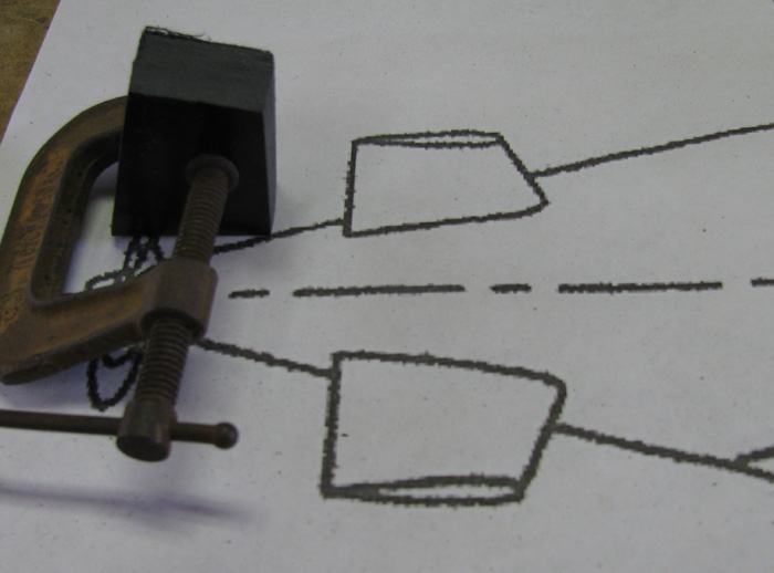
Start with a sheet of 1/16" plastic. 
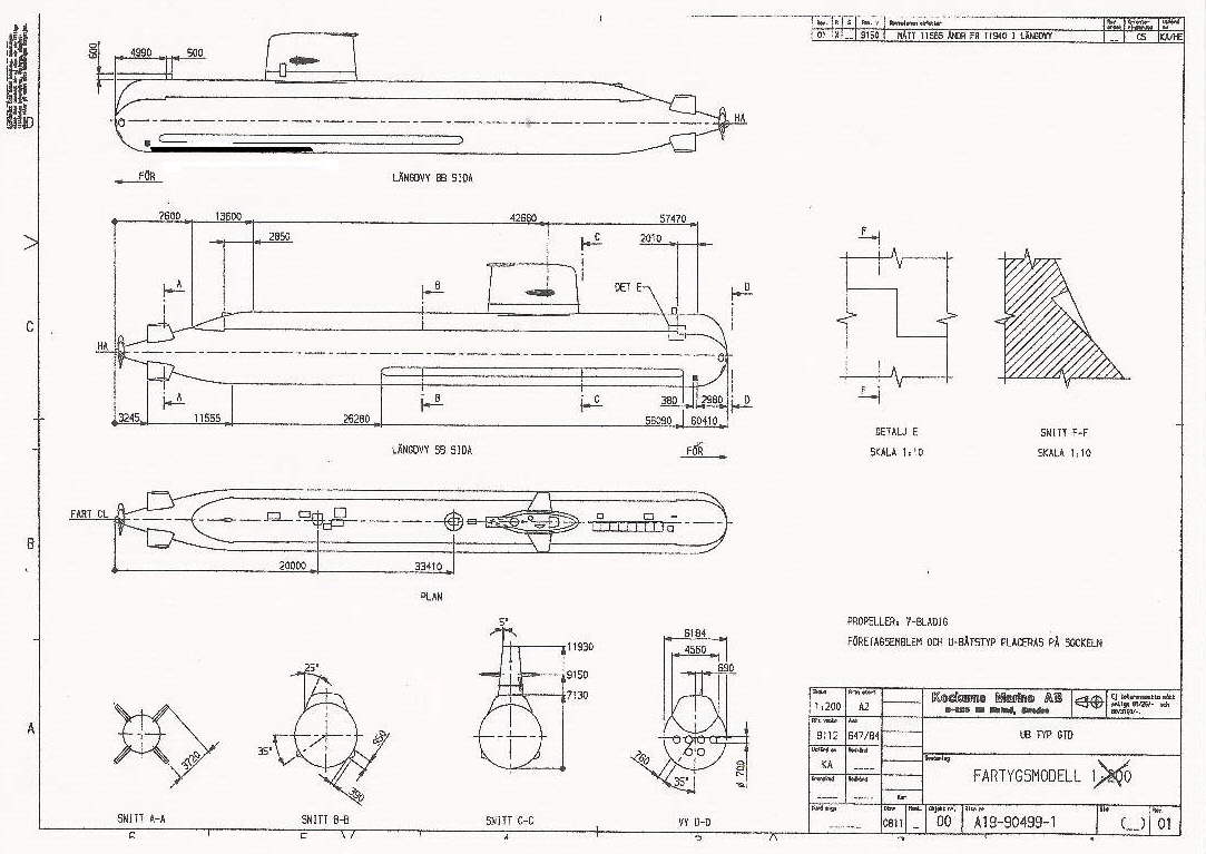
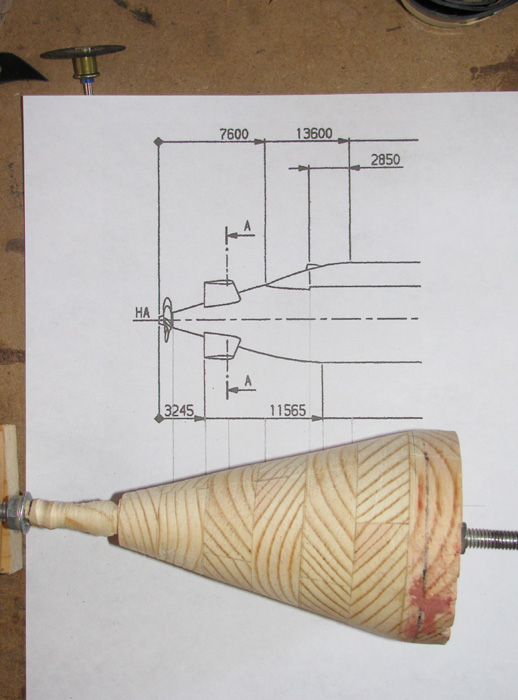
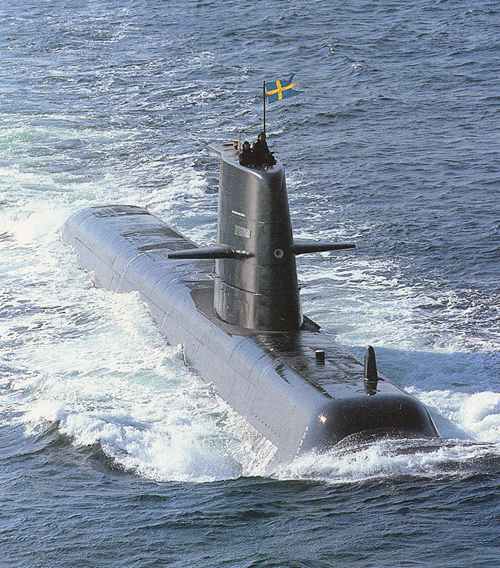
Using boat drawing, measure top of sail and bottom sail for maximum width and length.
Cut 2 for the top and one for the bottom.
Cut two pieces for the right and left side of sail.
Cut several pieces to make a solid nose piece that can be shaped. (took 8 pieces)

Join the 2 top pieces.
Join the 8 nose pieces

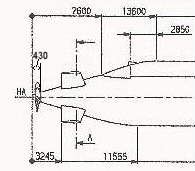
Check plans to get the side of the sail angle correct.
Make wooden jib to hold the angle during assembly.

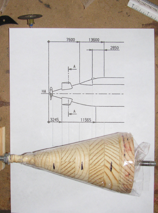
Once the cemented pieces have cured, using copies from the plans, trim to shape.
Top, Bottom and Nose.

I plan to make the sail taller than the plan and then inset it in to the deck where I can add support under the deck to the sail.

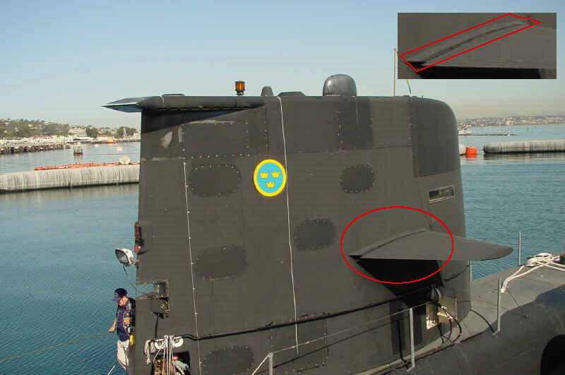
Got to remember there is a dip in the deck at the sail.
There also appears to be some sort of foot rail at the outside of the deck at the sail.

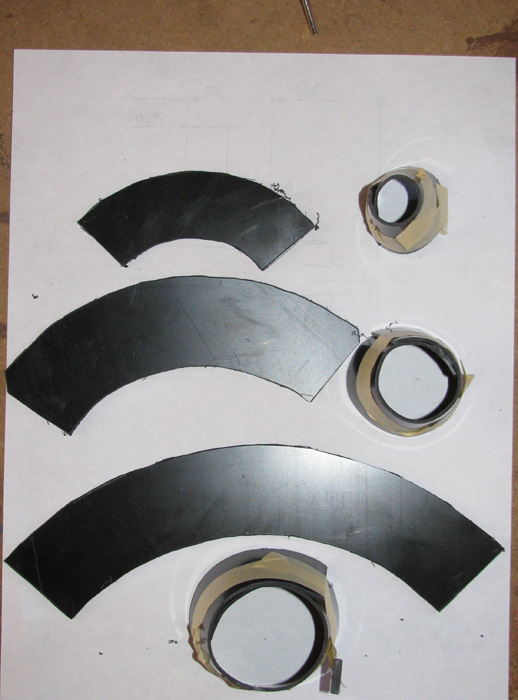
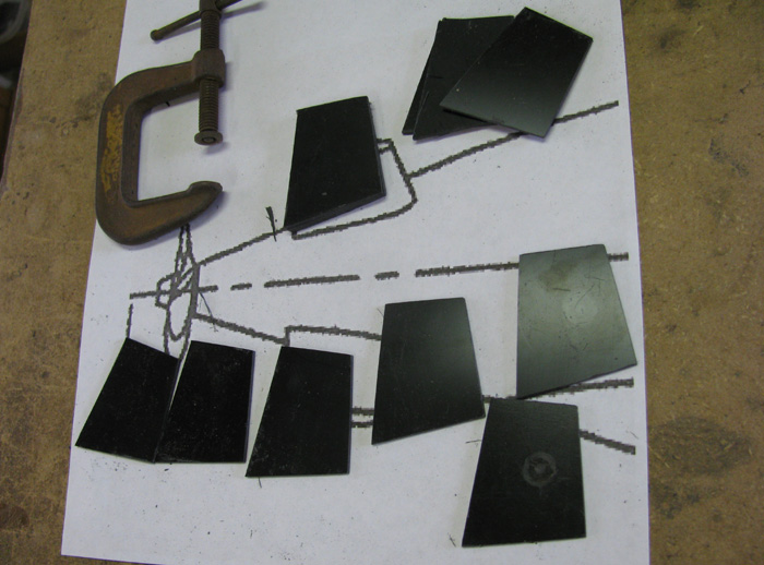
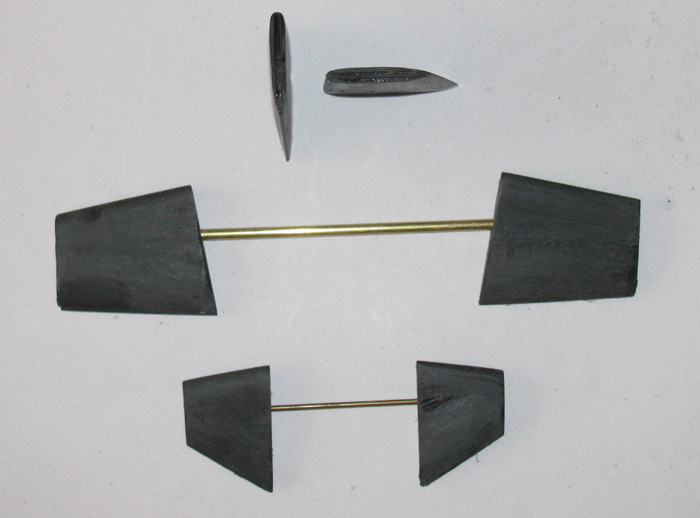
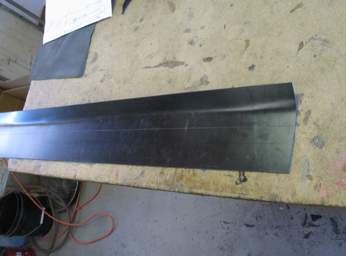
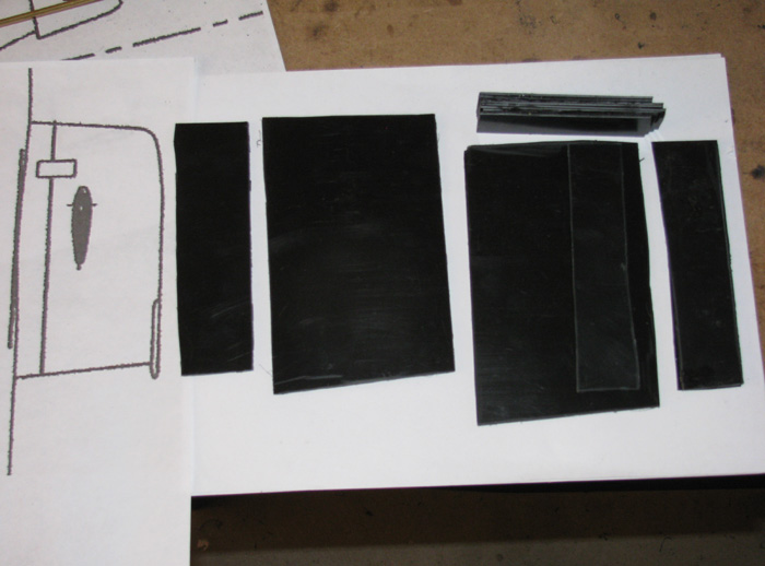
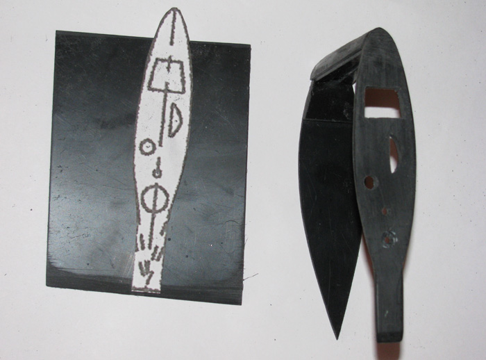
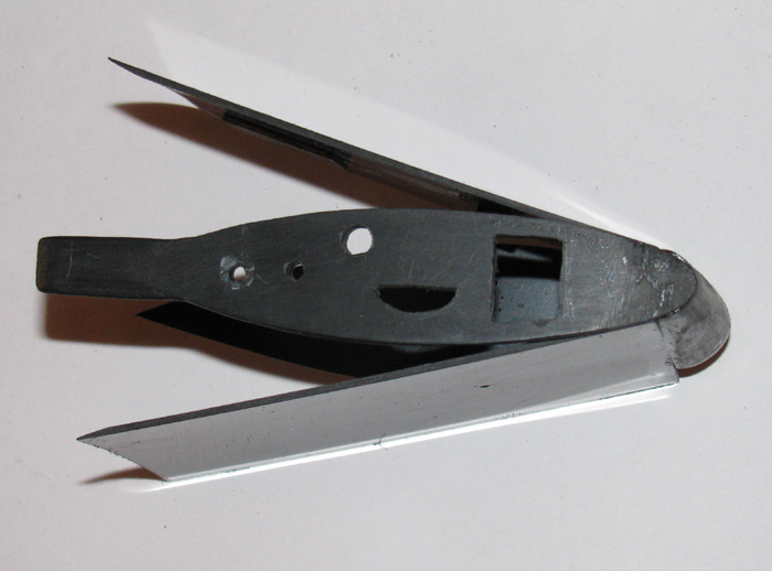
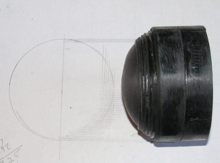
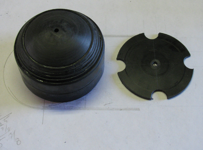
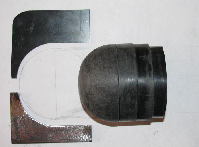
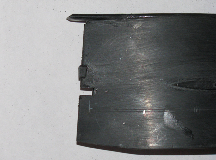
Parts cut from 1/16" sheet plastic.
Left to right.
1. Bottom plate.
2 & 3. will be the sail sides. I have already cut the bottom straight and the trailing edge angle of the sail.
4. Sitting on the sail side is the piece that will be cut 1/16" under size to the top plate to hold the sides in the correct location.
5. Two pieces of plastic bonded together to make the top plate.
6. Above the second side is the nose piece. It is made from bonding 8 pieces of sheet plastic together. It will be shaped and then two narrow plastic strips (not shown) will be place on the inside to hold the sides in the correct position.

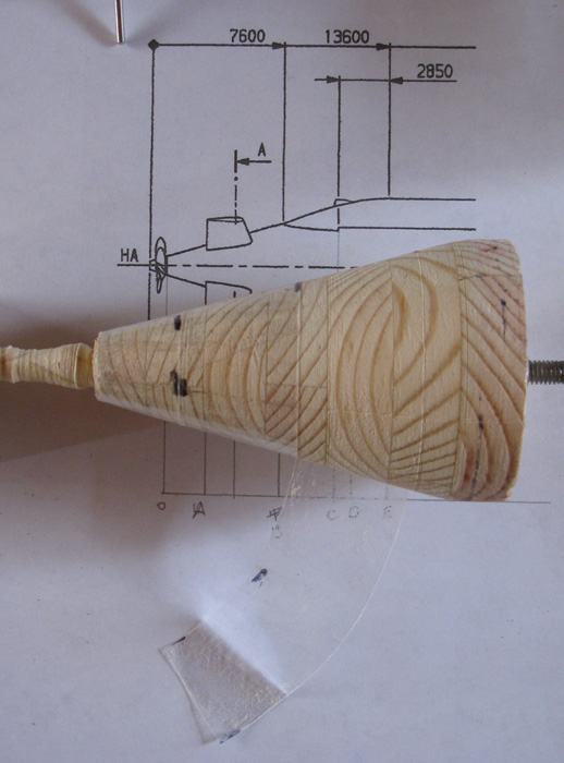
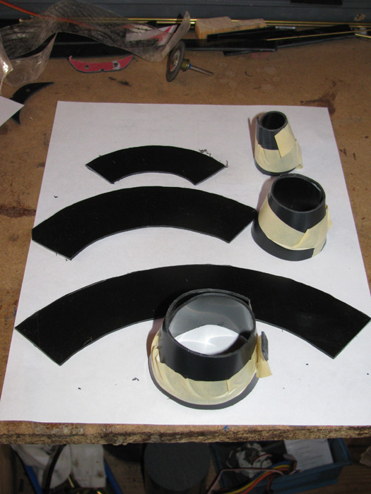
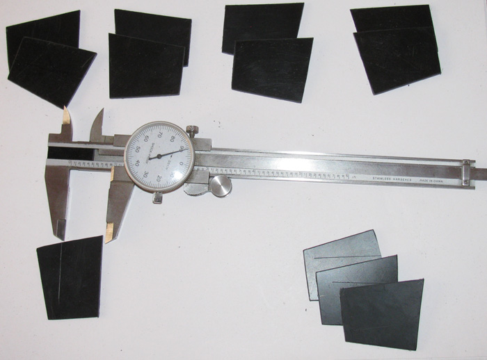
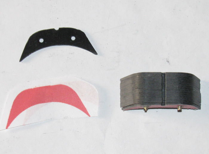
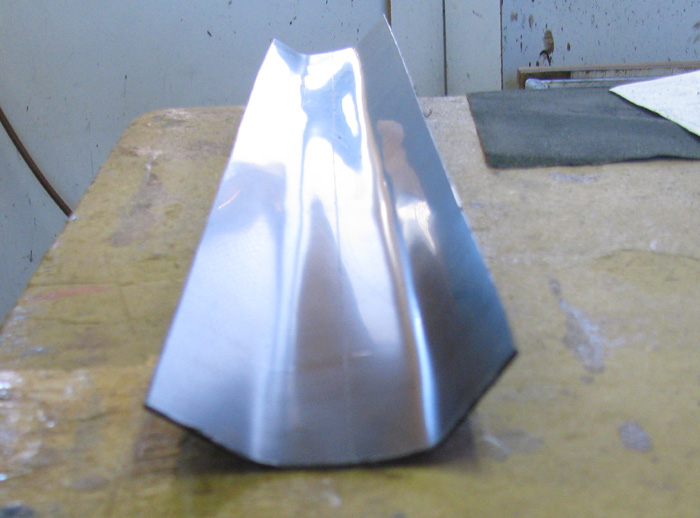
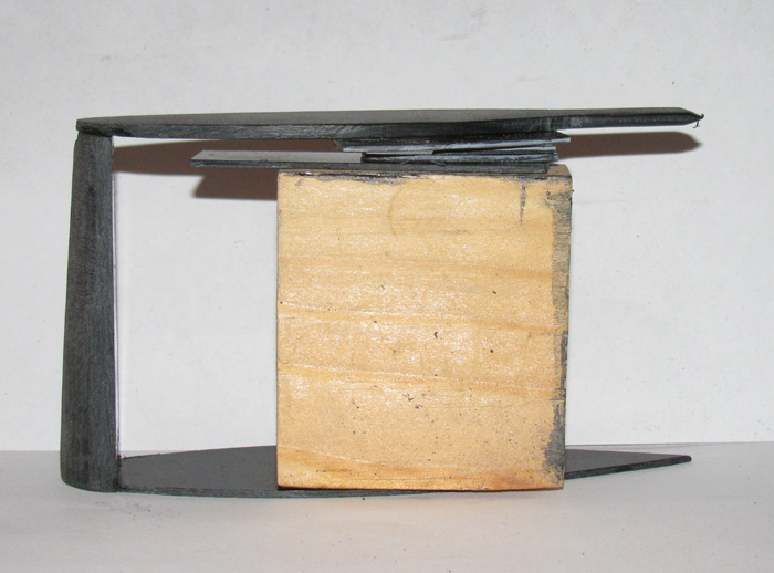
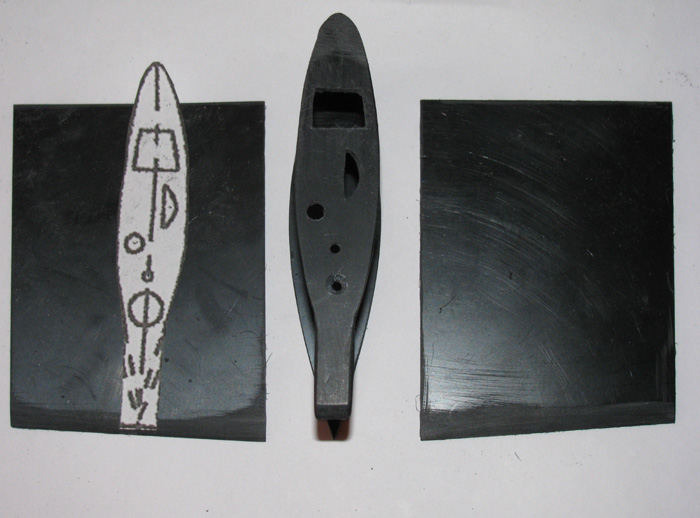
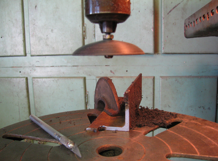
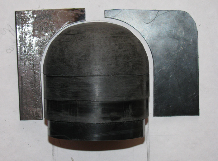
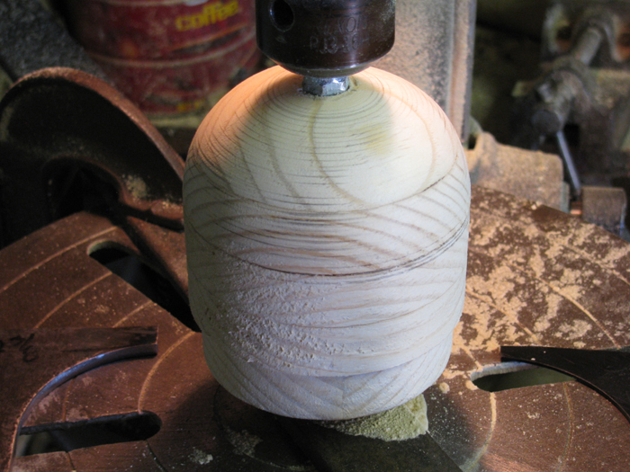
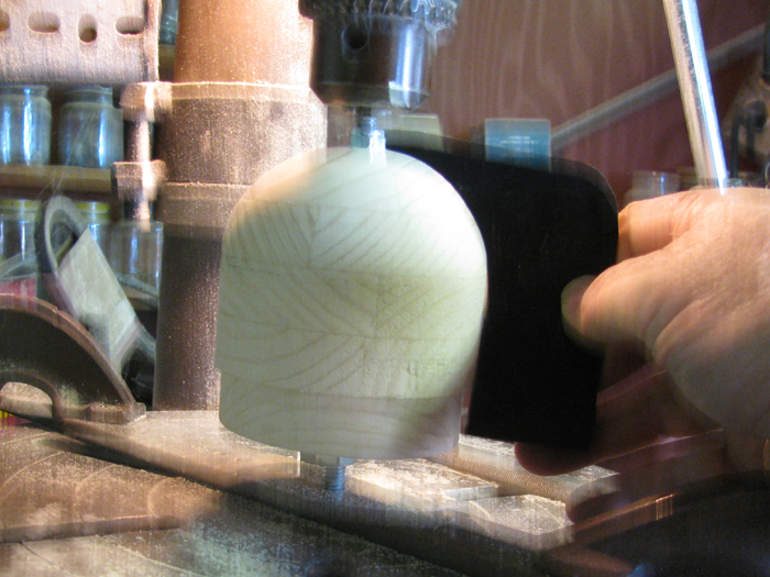
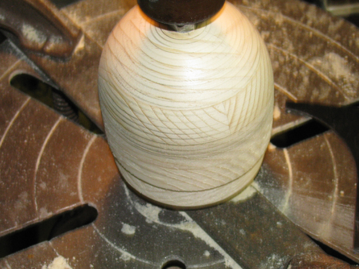
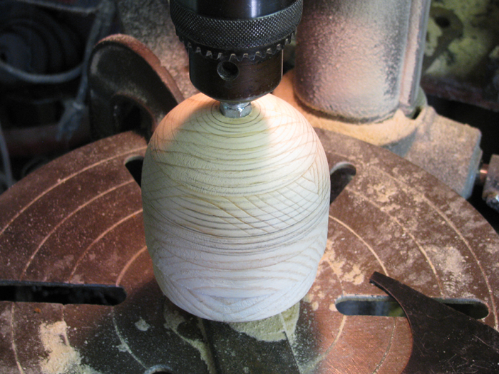
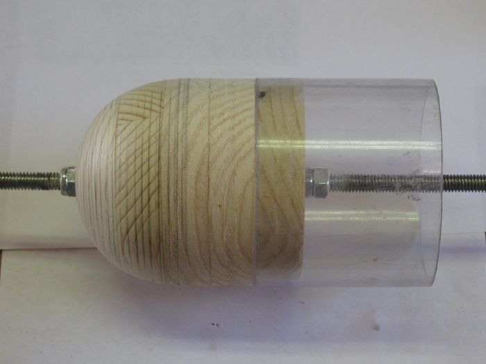
I started by hand shaping the nose piece of the sail. 
Using the top drawing to shape the top of the nose and the bottom drawing to shape the bottom then hand shaping the center to fit.

Then using copies from the full size plans I made sail top and bottom patterns.
I glues one to the top plate and one to the bottom plate.

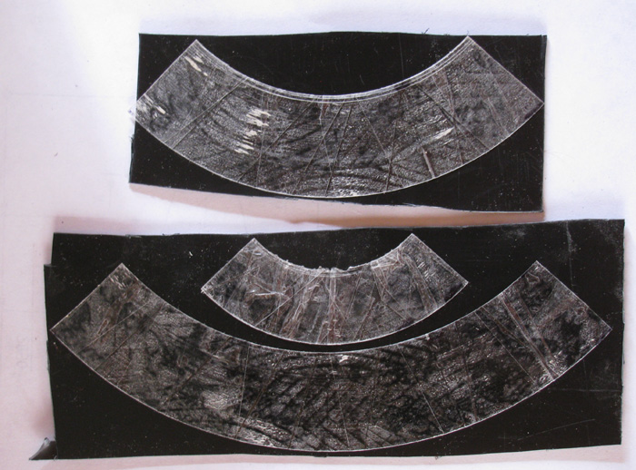
With Dremel, files and sand paper, I cut the plastic down to the plan for the top.
I cut the bottom down and another 1/16" on each side to recess the sail side panels in.

The two photos are the 3 pieces glued together.
I even shaped the exhaust on the rear top plate.

  .

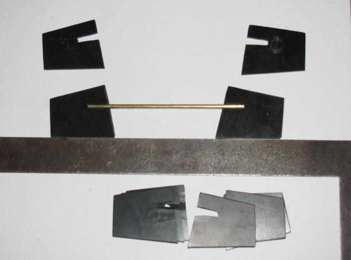
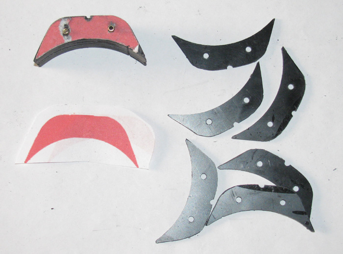
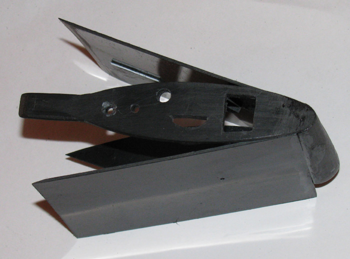
Next, I will fit small strips of plastic to the nose piece and to the top plate so the side plates will sit in place. Remember the sides go on the outside of the bottom plate. 

Below you should be able to see the piece on the back of the nose that is recessed to accept the side plate making it flush with the nose piece. 

I cut drilled and cut the needed holes in the top of the sail. The bottom most hole is only a location hole for the time being. That's a 1/8" hole that will end up being 5/8" for the snorkel head.

I don't plan to glue the sides on just yet. (maybe one side)
I need to make and install the sail plane bearing blocks.
And I need to make a couple of pieces to hold the masts and periscopes.
On this boat the masts and periscopes will not be permanent. 
I can leave them off or slip them in for display or running.

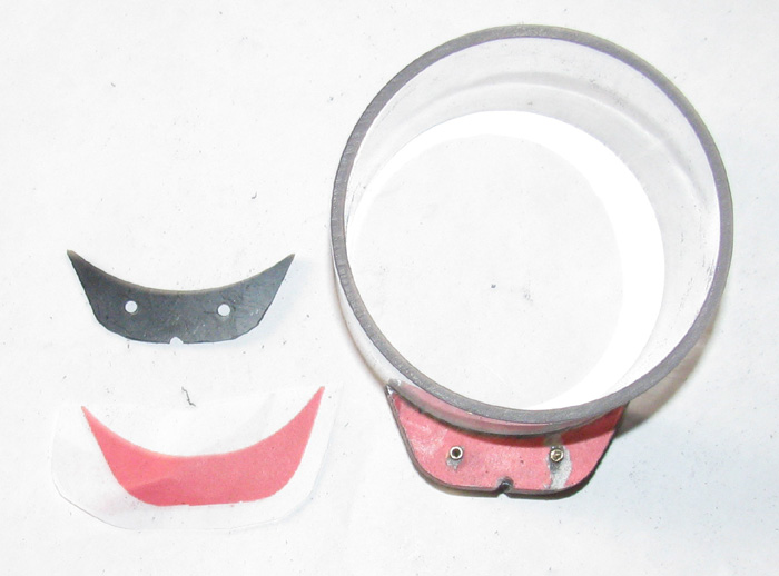
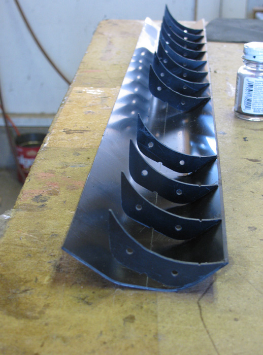
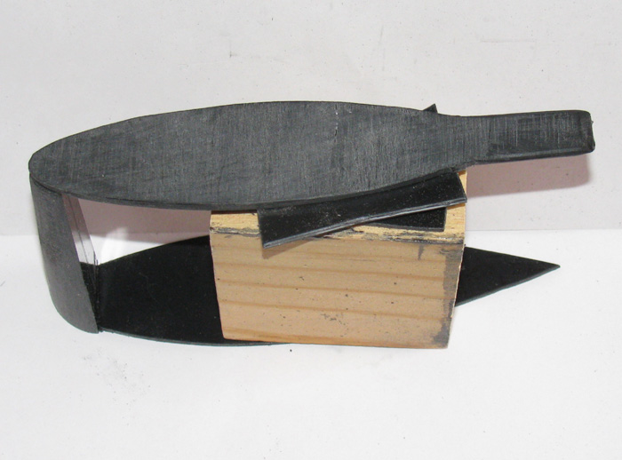
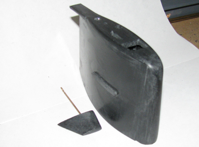
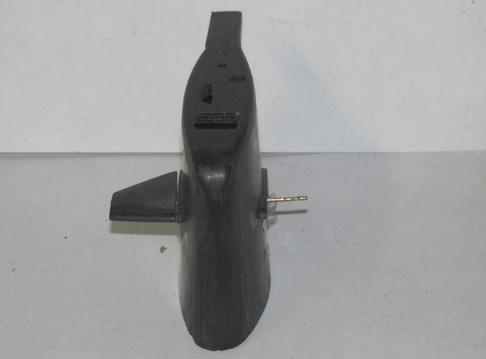
Sail plane bearing blocks are installed and a piece that will guide the bottom sail plate tot he side plates.
The two side plates are bonded to the nose piece. After it cures completely, I will start making the bend around the top and bottom plates. You can see the exhaust at the back of the sail. It is not in the way. The side plate fits under the top plate on a strip of plastic ledge, like the back of the nose piece. Basically the sides will be flush with the outside of the top plate.

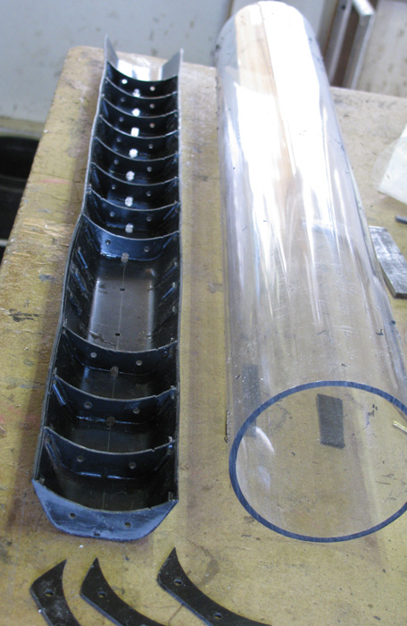
There is now a plastic box under the top of the sail.
This will hold the masts in place under way or on the stand.
The mast will just slip in to their respective holes.

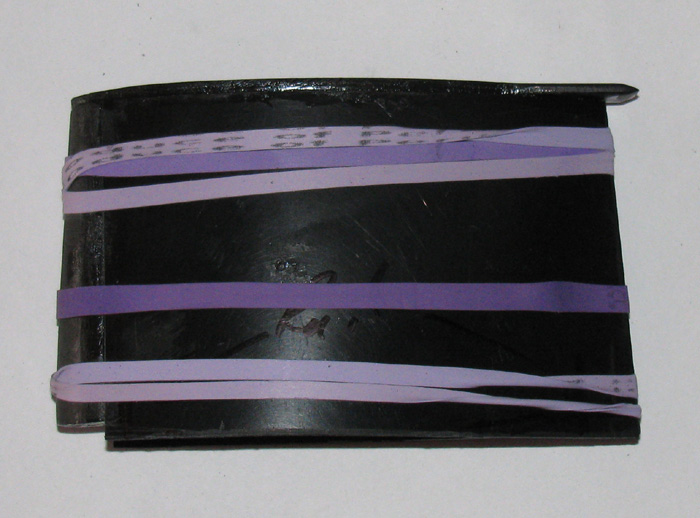
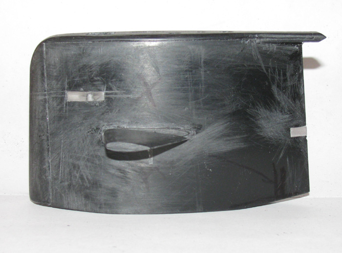
The sail has been been glues and the rubber bands are hold tension on both side panels.
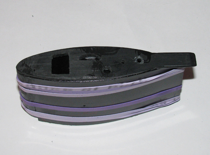
Side view and top view.

Once cured, I will shape the top nose of the sail and clean up the sides to nose joint and top of sail.

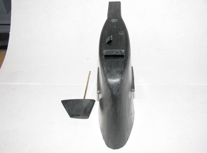
The sail has been trimmed to height. 
There is a block under the center in place. 
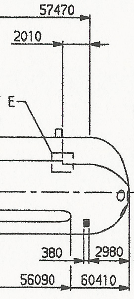
Where the sail sits on the deck there is a drop.
About 1" from the front the deck tapers up.
About 1.5" from the back the deck tapers up.

On the view above you can see the notch at the nose piece.
The nose piece is correct for the deck and so is the center of the sail bottom. 
That drop measured out about 3/16" so three layers of sheet plastic.

The pilot hole for the sail planes can be seen on the side view.

The exhaust was completed at the rear of the sail.
The top of the sail nose was rounded off and shaped.
The sail plane stand off blocks where added to both sides of the sail.
A little more fitting needed to get the sail planes and stand off blocks to meet properly.
Actually the parts are rough sanded to fit and I need to get after the parts with fine sand paper and/or a finish file.

Looks like I need a profile photo.

Got it. But this was after I took some 1/4" clear plastic and thinned it down and shaped it for the port and starboard running lights and the rear sail running light. 
They are just set in place for now. Will be place permanently after painting.
The port and starboard light lens is a single piece that goes all the way through the sail.
There are two small holes drilled in the bottom of the plastic that will be painted green and red.

There is a rear light fixture at the back of the sail to be made.
Above the flood light.
It's about center top to bottom.
Will need to scale the photos to get the location closer.

Making the rear light fixture.
I tried to make a piece that was vee shaped. 
Total failure. Couldn't get the vee right. 
When set in place the thing would spread apart.
While trying this, I was looking at the clear lens slot.
Why Not do the same thing for the light fixture. DUH!

So I measured and made the slot.
Next I bonded two pieces of sheet plastic scrap together. (correct thickness)
Once cured, I shaped the piece to fit the slot.
The I rounded of the edges to match the photo.


Glued in place while the piece was still long so, I would have something to hold on top.

After it cured, I used the grinding cut off wheel on the Dremel to get the protruding length near the right length.
Then I filed it down slowly keeping the angle lined up.

The pencil mark below the clear lens slot is the mounting point for the hand railing.
Got to think about how I will do this. 
This might requires some jib building and will take patience on my part.

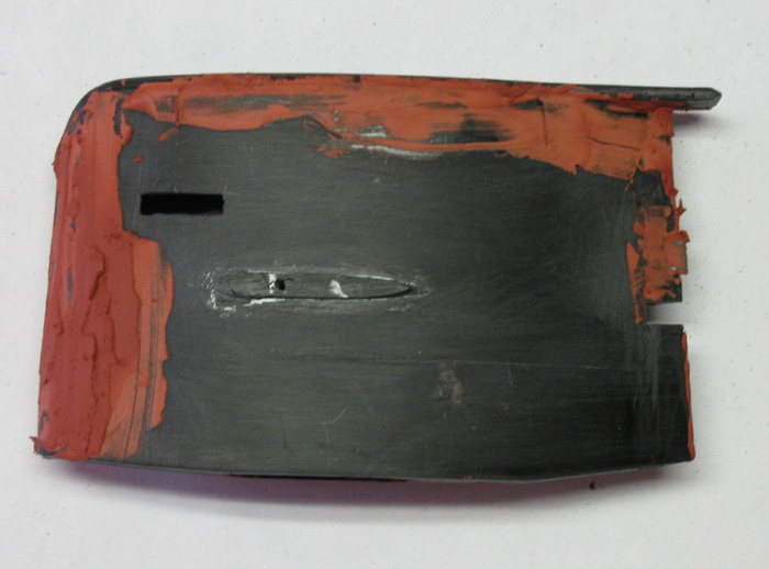
I decided to do clean up on the sail for primer.
Got out the glaze and when after the places needing attention.
Mostly seams where pieces of sheet plastic were bonded.
Tomorrow while in town getting screws for the Skipjack project, I need to get some 200 & 400 sand paper.

In this profile of the sail, should note that the sail is 1/4" too long at the bottom.
This is so I can inset the sail in to the deck.
That 1/4" lines up with the front and back which will be flush with the deck. (some day)

There's a dome of some sort on top of the sail.
Need to look at more photos to figure out what the shape is and where it is mounted.

There are other items sticking up above the sail but those appear to be masts that are not fully retracted.
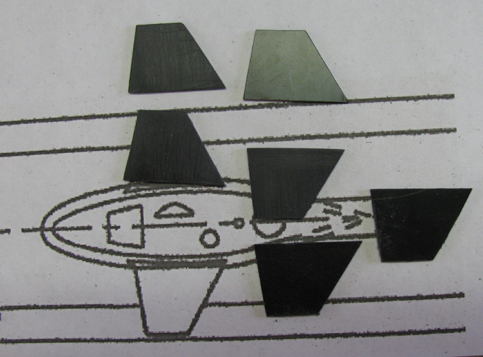
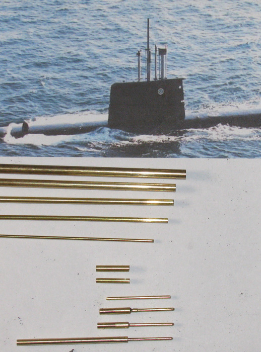
Masts

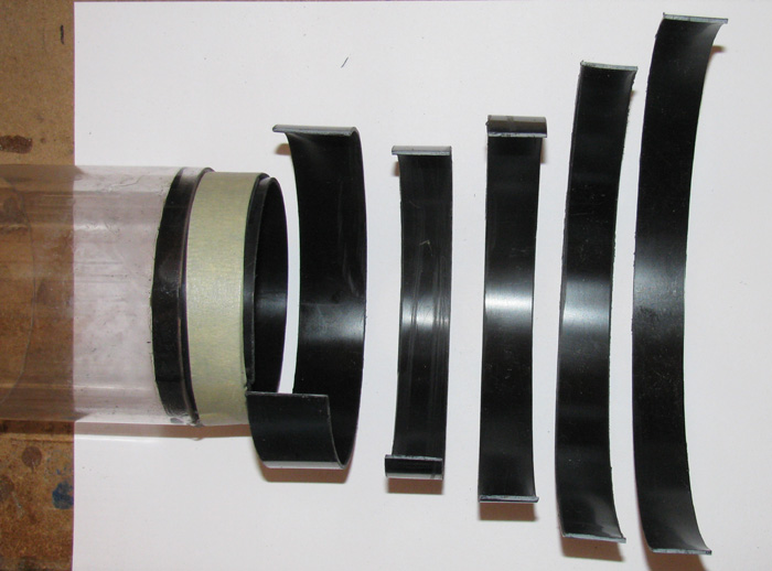
Using various size brass tubing and 1/16" brass rod, I thought I would start on the masts.
Using several photos I have found on the internet, I used them to scale the mast diameters and heights.

I know the sail height. The sail width at the top, bottom and at the sail planes. Using these numbers I was able to to guess on the masts information.

Brass tubing at the top 4 items in the photo. 1/16" brass rod is the fifth item.

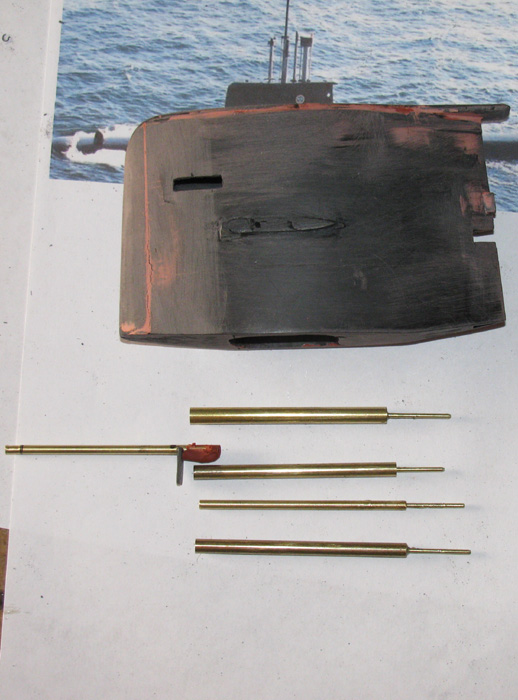
When building the sail I put a plastic box in the sail to accept the masts. The box is 7/16" between the top and bottom and 1/2" from the top of the sail. I drilled through the sail top and the top box levels when I located the masts on top of the sail.

Using the 1/16" holes I drilled the openings in the sail top for the masts that would be going in those locations. The snorkel hole has not been enlarges yet in the photos above. 

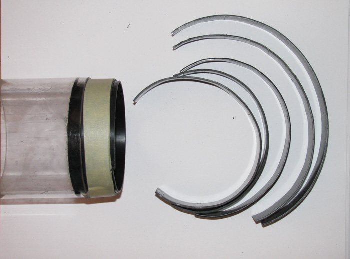
I made four 1/16" pins (1 1/8" long) that will go through he two levels of the box under the sail top. 

Then I cut 1/2" long, 3/32" tubing to fit over the rod. I cut 1/8" pieces as well and a 5/16" piece.

I bonded the tubing on to the rod and added a second and third piece of tubing as the mast would require. 

I roughed up the finish so the glue would bond.

The bottom items is the periscope mast. Just have to shape the head when the glue cures.

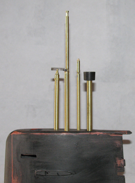
Top is the snorkel mast.

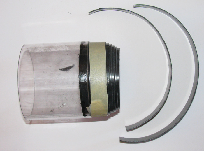
Next is the communications mast. It is two parts and I have not finished the top. It will insert in to the lower section but I have to reshape the bottom as the top is off set to the back of the lower section. Glaze on the one side to be shaped. The plastic piece is temporarily the stop and will be removed. 

Third is the periscope mast.

Fourth is the radar mast. Making the radar receiver is next. Was going to make two pieces of plastic and then put pieces in to separate the top and bottom of the thing. But. Not practical. Size here is an issue. So, I think I will take a piece of clear plastic. Shape it and thin it to the correct thickness. Then I will polish the clear plastic so the sides are transparent. I will then put grooves on the back to represent the frame of the unit. Paint the top, bottom and grooves black. When dry, polish the back again leaving black paint in the grooves. That should do okay.

The mast push in to the holes in the box below the top of the sail. They are a tight fit and will stay in place even upside down. I plan to put the masts in place when displayed. And they should be find if I choose to run the boat with the mast in place.

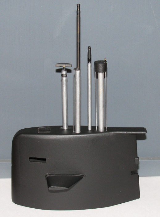
I have detailed the masts.
I have three pieces to add.
The snorkel gets two rods. One front and one back.
The tall communications antenna gets one on the front.
 

The radar antenna is a single piece of clear plastic, shaped.
I cut grooves on the back side to represent the frame.
Painted the top, bottom and back with black.
After it dried, I sanded the paint off the back leaving paint in the grooves.
I like the effect. I can see through from the front and see the black lines in the back.

The masts have been completed.
The first coat of dark gray primer is on the sail.
I thought I would show it off. 


Project 5... Bow

The bow is a 3.5" diameter sphere.
So how to go about this.
Using the drawing numbers, I see I can make it a half sphere or I can add a straight piece then the half sphere.
I need to take in to consideration where the deck drop is located near the bow.

Okay, the decision is to make the bow assembly to the deck drop.
So, 1.75" for the bow sphere and 1.05" to the deck drop.
The assembly will need to be 2.80" total length plus the engagement in to the cylinder.

 I started by making a 1.25" wide piece strip of sheet plastic.
I hand formed it until it fit inside the cylinder test piece I have that is about 3" long.
I slowly cut the length of the strip until I could get it in to the cylinder with a little bit of effort and have the ends meet tightly.

I used silicone grease on the inside and front surface cylinder so the plastic cement wouldn't bond the sheet plastic to the cylinder. I put the strip in the cylinder then went over the plastic with cement. I had also made a strip 3/4" wide to put on the inside to hold the first strip firmly in place while the cement bond cured.

You can see, I had made several strips that will be place inside each other.
I put the cement on and put the strip in the cylinder.
Once fitted, I used masking tape to hold the strip in shape that was outside the cylinder.

Here, you can see the curve I put in the plastic strips before fitting and bonding.

This image shows 5 strips in place.
The two strips not in place are actually going to go on the outside of the strip in the cylinder to raise the diameter to that of the cylinder.

I have cut several square pieces of sheet plastic which I have cemented in a stack which I will turn in my poorman's lathe to make the very front of the bow. It will be stepped to fit inside these rings I just put in the cylinder. 

I also, have a disk of plastic that will be temporarily place inside this mess.
It will be used to hold the center when I put it all in the drill press to do final shaping of the bow assembly.

Next is to make a wooden pattern the shape of the final bow assembly.
Need to do some numbers to make sure I get the front disks in the correct place.

Here is the nose disk after turning it in the poorman's lathe.
I use my Exacto knife as the chisel to remove material.
I stopped often to check against the profile pattern. ( the 3" piece of cylinder)

Checking the fit and the depth needed to get the full semi circle.
The nose should meet the straight part at about 1/4" right of the line cent of the flat section. 
The pencil drawing was used to determine how to make the plastic rings so that I would get a minimum of two layers of plastic when completed.

I set the nose against the test piece of cylinder to see how it is coming together.
Now that I have the nose section, I found that I need to add 5/8" more to the straight section to get it to line up with the deck drop. This is where I plan to have the nose disconnect from the main cylinder. 

The piece on the right fits inside the back of the bow section.
It will be used to hold a shaft through the complete assembly so I can turn the assembly in the drill press.
I will be able to finish the nose hemisphere and trim to finish length.
The notches are water drain holes. 
Don't want the nose filling up with water and holding it.
I will a round block of plastic pieces that will screw to this plate. 
The block will have the metal shaft glued to it. 
After finish turning I can unscrew the block and rome it from the assembly.
Then I will fill the hole in the center of the nose and finish by sanding. 
But before I do that, I need to layout the deck that goes on the nose. It may cover the hole and be used as a drain hole. 

The parts have be bonded and are curing.

I did some shaping by hand with my Dremel and a sanding drum.
I used a plastic template of the profile to help see where to remove material.
As I hand shaped the bow, I realized there were soft spots and hard spots in the plastic.
I could not get a perfect circle cut.
I decided to make a steel cutter to cut the to finish the profile.
Plastic template is at top and steel cutter is at the bottom.

The above photo is to show how close I got with just hand shaping, free hand. 
  
Work on the bow section has come to a stop.
While trying to get the final shape, the plastic had a loose seam and the cutter dug in.
The rounded front end exploded in to several pieces.
 
So for now, I am moving on to another project.
==========================================
It's been some time since I posted to this build.
Finished up my Skipjack.
Started on a project I have wanted to do for several years .... more than 30.

B-boat  1903.

However this morning I was looking for the spindle that I use to turn plastic and wooden disks in my drill press.
Found it with the wooden disks already mounted for the new Gotland bow.
  
So, what the heck.
Why not just do the bow plug for the Gotland.
 
Next photo shows the wooden disk have been cut vertically to the proper diameter to match the cylinder diameter. 
It also shows the round front of the bow being shaped.
By hand, I roughed in the shape with my 4" grinder and a lathe chisel.
While spinning I can feel the hard spots in the wood.
By using a pencil and lightly touching the spinning part, I can put marks on the high spots.
The photo shows the high spot facing us.
I take a file and remove the marks.
The spin it again and clean it all up with a file.
Mark with pencil again.
Keep doing this until I get the high spots down to the rest of the part.

   
I made a profile template out of plastic to help get the final shape.
Here it is very close but still a couple of high spots.

   
Here's another look at the pencil marked high spots.
Again with the file.
Oh, I do this filing while the part is not turn.
I just file the pencil marks off and then spin it again.

  
Here, I have pencil marks all the way around.
I am good with this.
The part will be glazed before finishing up the part.

   
Test fit of the part in to my short cylinder peice I use for this sort of thing.
The pencil marks are still on the part.

Project 6... Scribing
Project 7... Equipment (wtc)
Project 8... Paint

Beings the cylinder is the hull, it will be painted. This will not allow me to see inside the cylinder to look for leaks. 
Solution. Hold the deck/sail on with one screw and interlocking pieces or magnets. Tape off the very top of the cylinder under the deck and out of sight from the outside so as to leave a clean strip on the cylinder to see inside. I will have to turn the boat upside down to check for leaks. Not a problem. Or maybe just under the sail and make it removable. I think I like the strip the full length of the cylinder so I can see all the equipment in case I burn something up. Will see as I go. 

.