Now that my Akula II and Skipjack have reached a point that they run
really well and at most need some fine trimming,
I found my self with nothing to.
Well there is the ALMA but that's painting and the weather has now
turned cold. (Did I mention I hate painting)
Last Sunday I was going back and forth to the shop where I also do my
laundry.
I keep looking at the Type VII and Gato sitting on my back wind porch.
I like the looks of the WWII boats but looked in to the history and
various changes between boats.
I can not tell one from another unless I have photos side by side.
So I decided to drag the Gato out and work on it.
Why? I just bought some wtc tubing to do a complete rebuild of the
George Washington wtc
Turns out the tube is 2.5" in diameter and that just happens to be
the diameter for the Gato.
So I got enough to do both.
I do not plan to modify the looks of the kit boat but there are some
thing I will leave off so this can be RC.
There are so many small fragile parts that would not last long going
through the weeds at the pond.
One more thing to point out.
I will probably bounds around from one thing to another.
==========
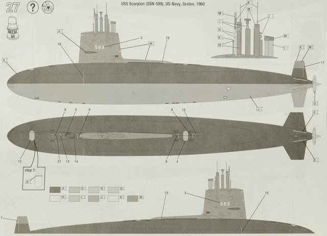
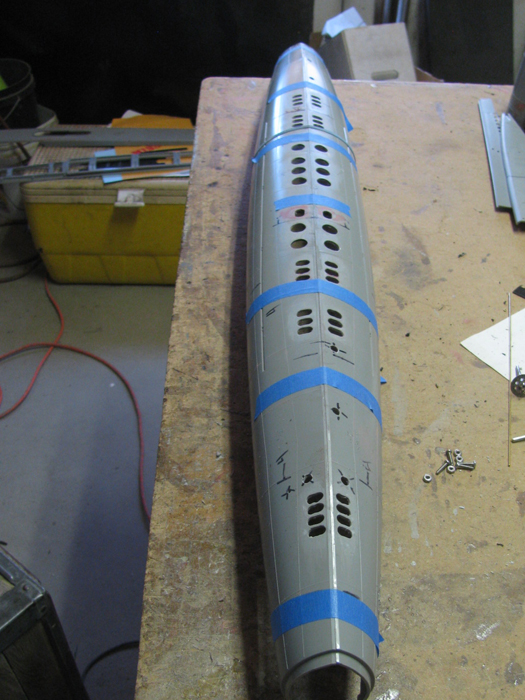
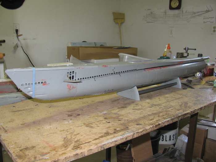
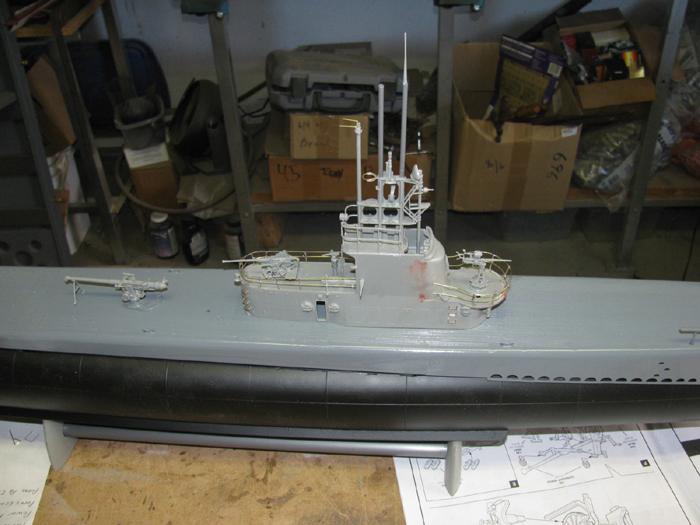
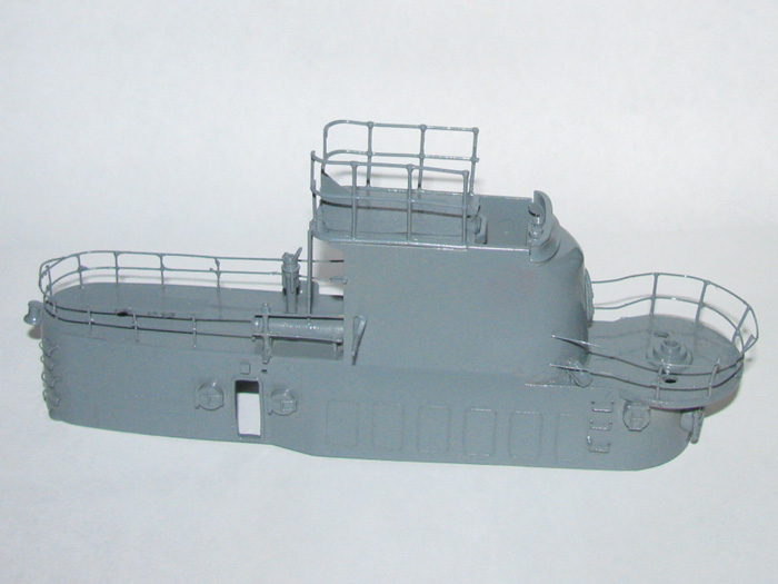
It starts. - November 20th =================================================
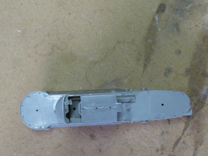
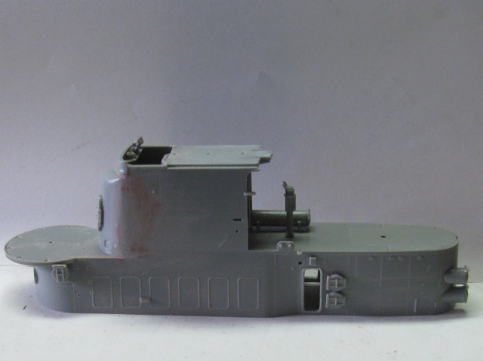
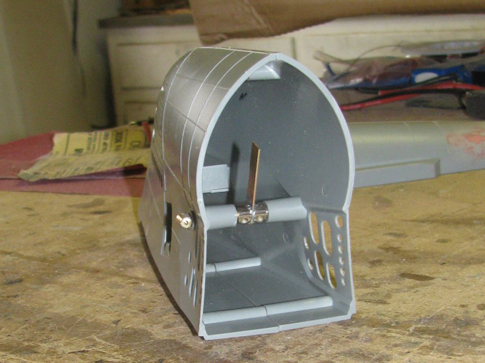
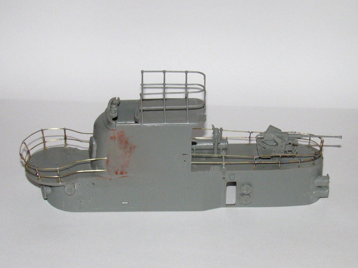
I forgot to take a photo of the conning tower before I assemble the
lower section.
I would have liked to cut the two side doors out but with the conning
tower sided already glued together, I am not sure I want to cut in to it
now.
We will see.
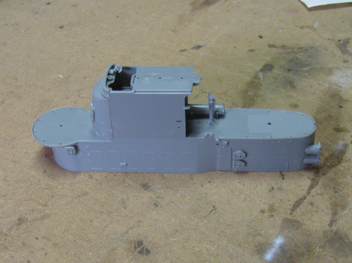
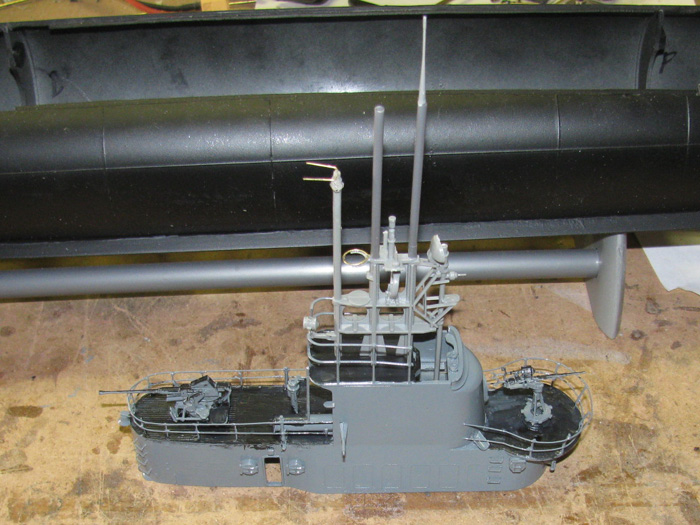
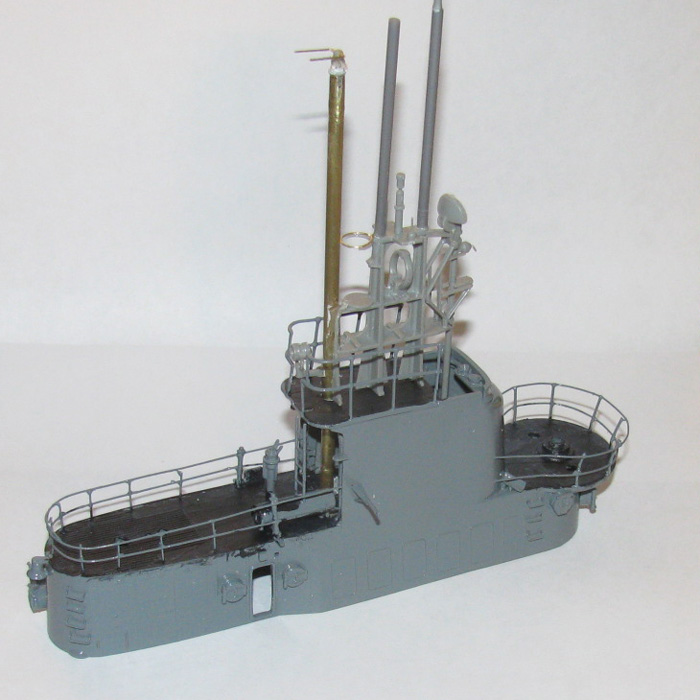
Top of conning tower.
I have drill two 1/4" holes in the floor of the bridge to let air out.
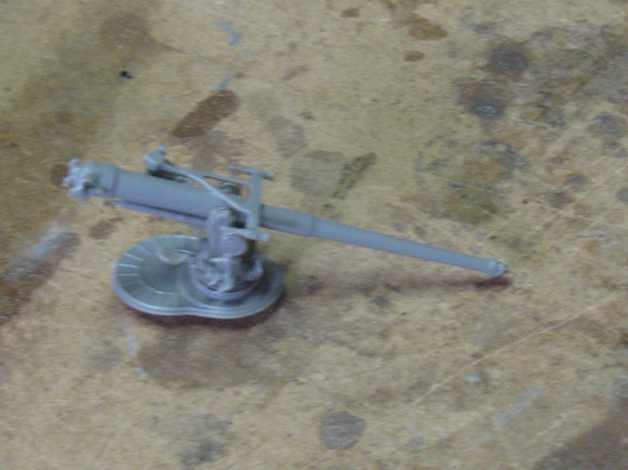
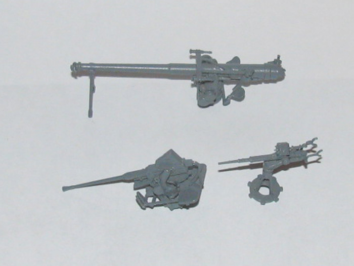
4" gun assembled.
The gun is not installed to the deck mount yet.
November 22th =================================================
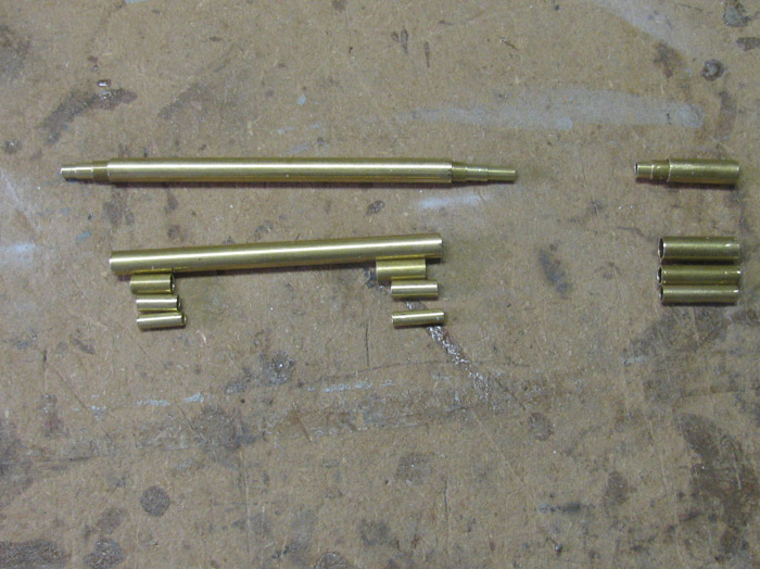
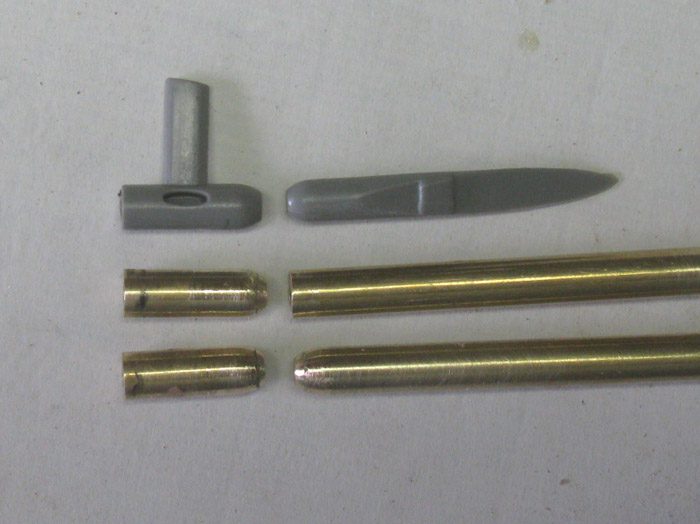
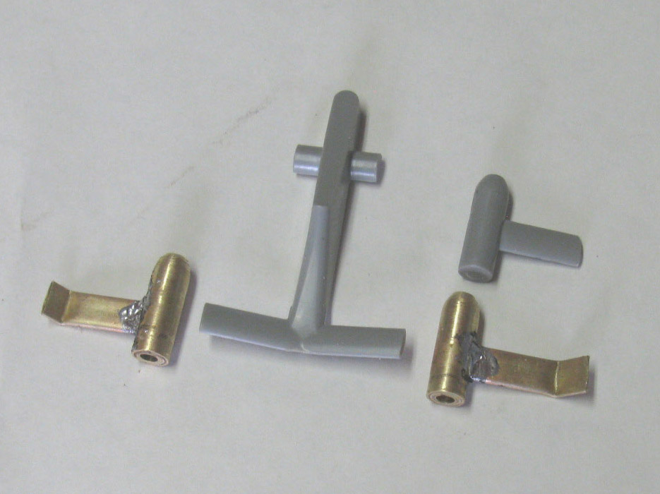
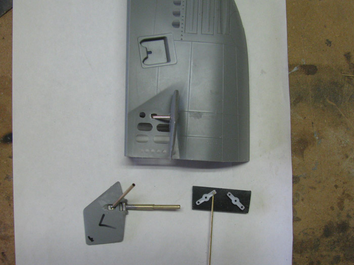
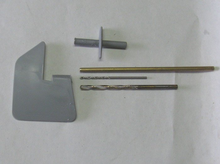
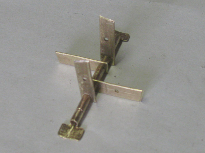
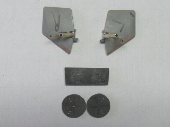
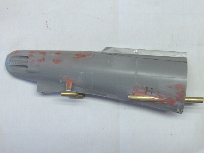
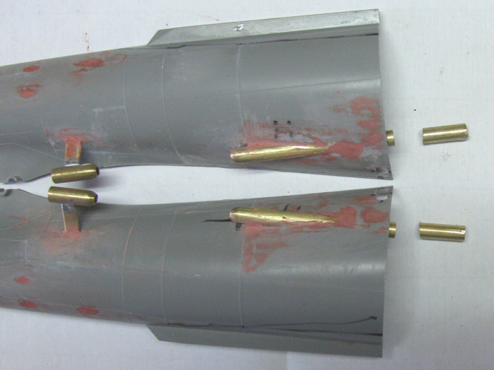
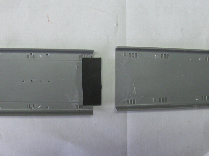
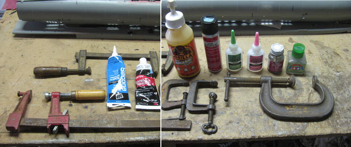
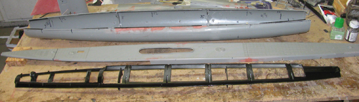
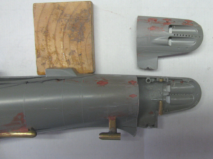
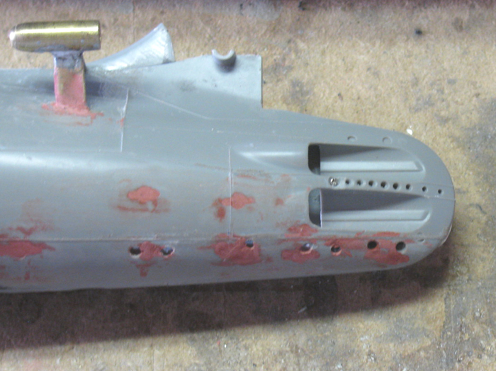
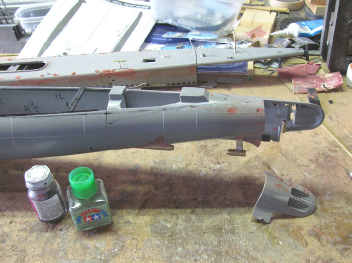
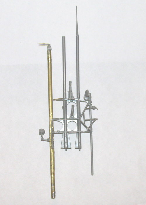
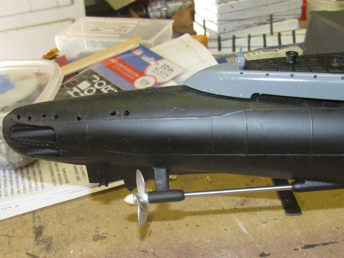
What you are looking at are the parts to make the propeller through
hull tubes and the back support struts.
All those short pieces of brass are to size the outside tubes down
to accept the 1/8" propeller shafts.
On the right is the through hull tube with the short pieces being the
shaft bearings.
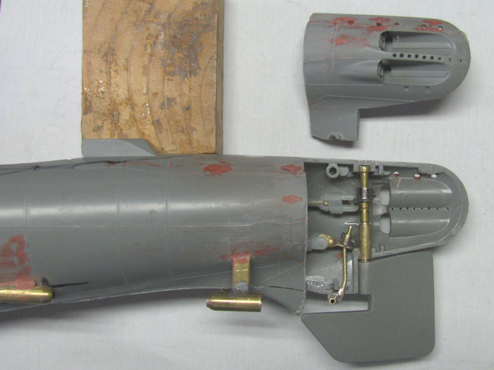
I will shorten them so they are the same length before in stalling
in to the long tubes.
I will use a length of propeller shaft to align the bears as they cure.
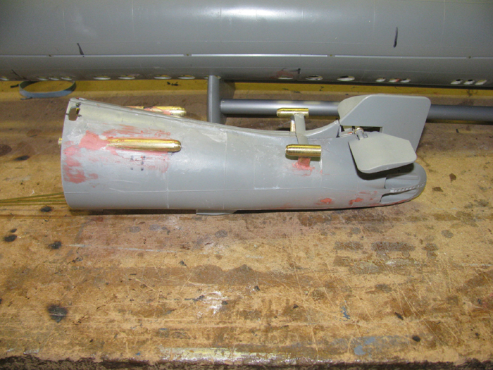
The parts on the right are the rear support struts.
The will be shorten to match the original plastic parts and one end
will be shaped and the other flat.
Those parts are no assemble yet.
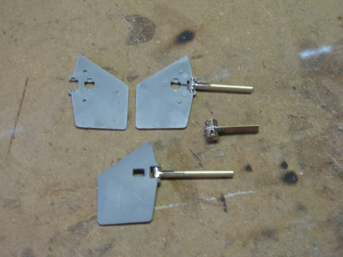
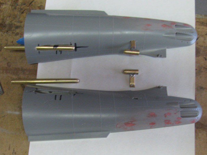
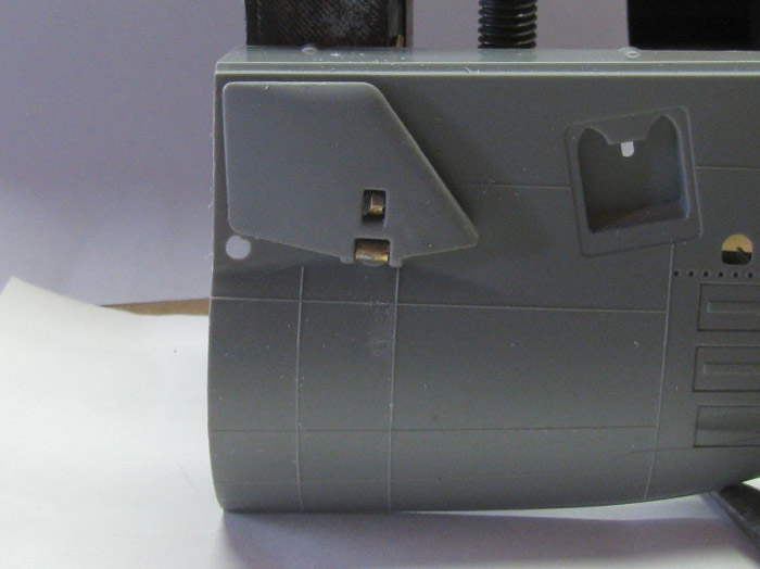
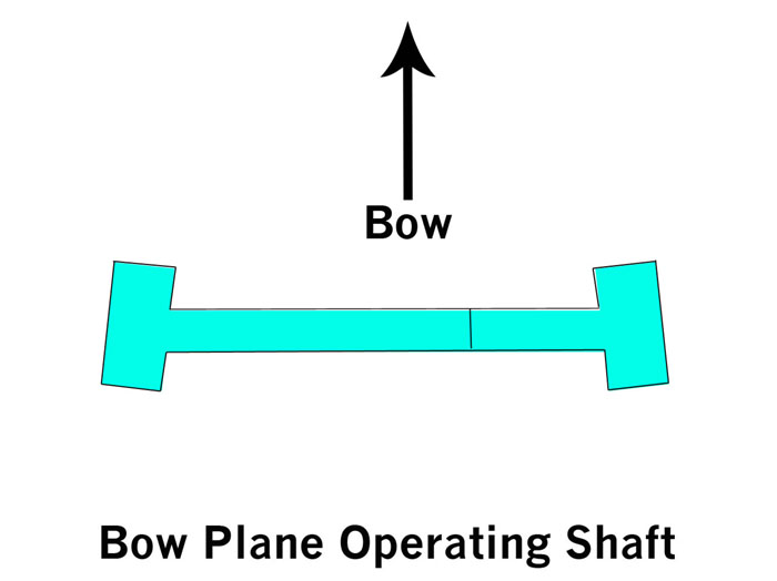
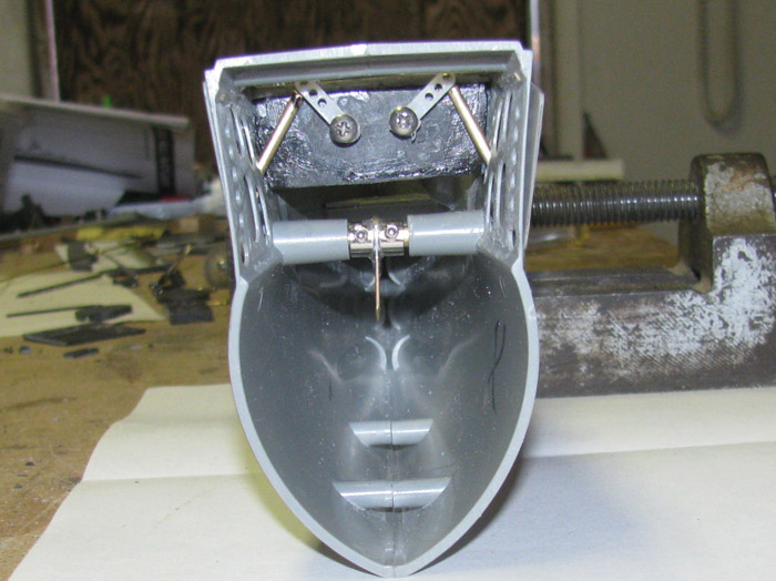
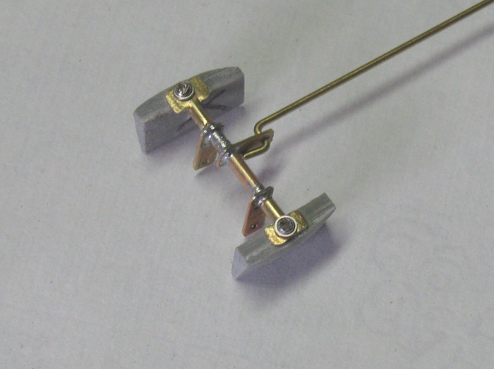
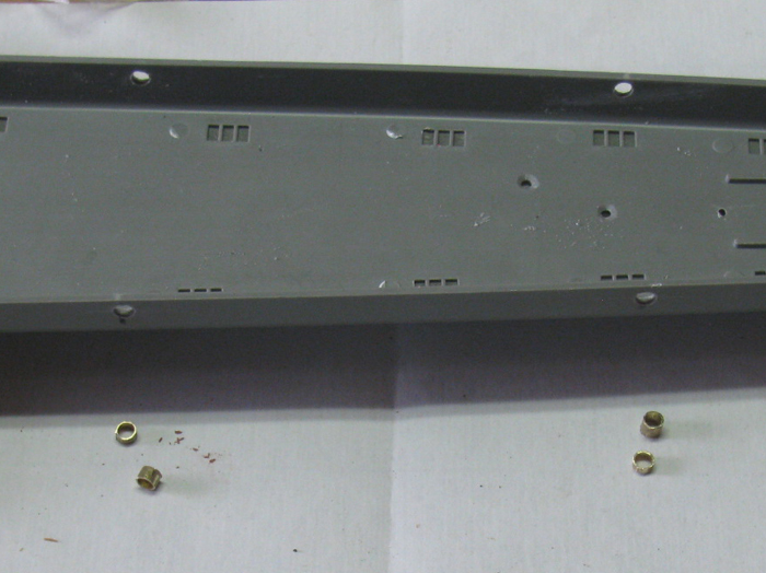
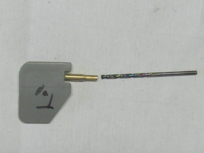
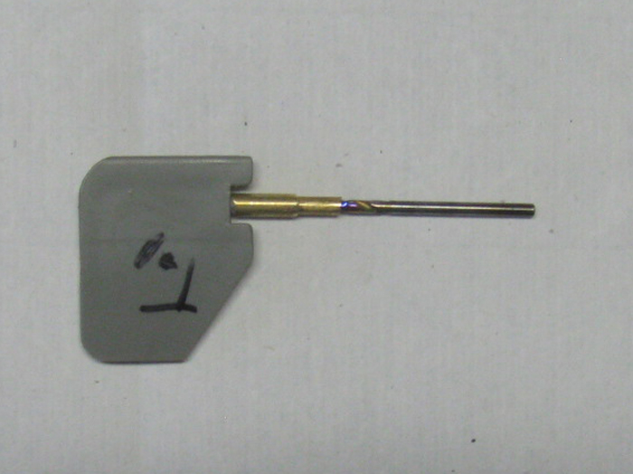
I did not think the plastic bow plane operating parts would hold up.
Build new ones out of brass.
I cut several sizes of brass tubing to match the outside diameter and
the pin size.
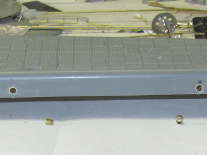
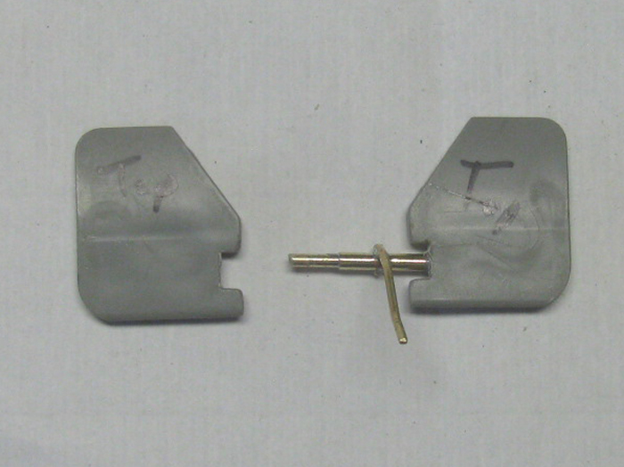
I plan to use two wheel collars to make the control horn and connect
the two bow planes shafts together.
I made the brass horn by flattening 3/16" brass tubing.
Then I drilled a 1/8" hole on one end.
I put the wheel collars and the flat brass on a 1/8" shaft.
I soldered the three pieces together so I can get to the allen set
screws when in the boat.
The horn is long so I cut it to fit later.
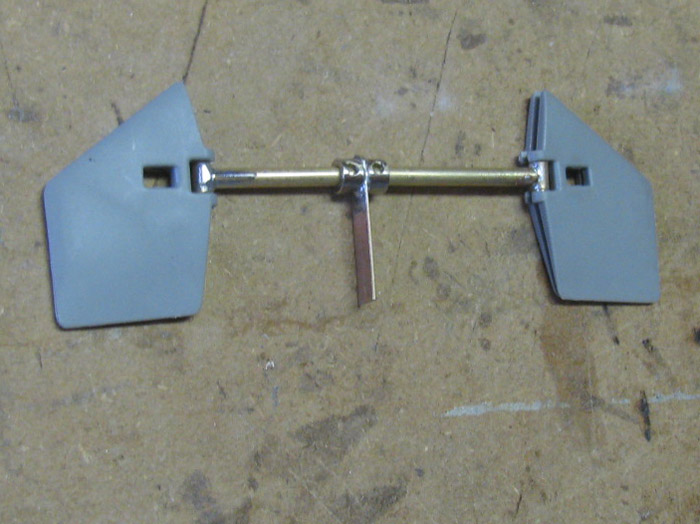
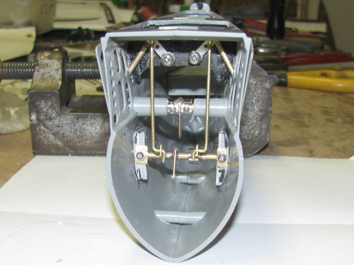
I then drilled through the collars and brass strap to get the hole
large enough to accept the bow planes shaft.
This shaft is smaller than the hole in the plastic bow pieces.
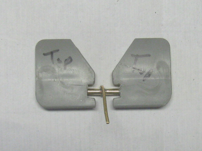
I made two short brass tubes to act as bushings and pushed them through
the hull with a spot of CA on them.
I had a long shaft going through both hull halves and bushings to keep
every thing straight.
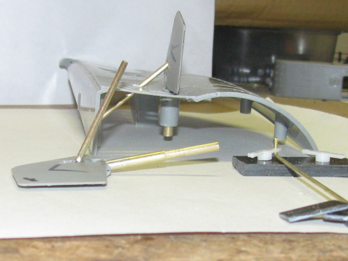
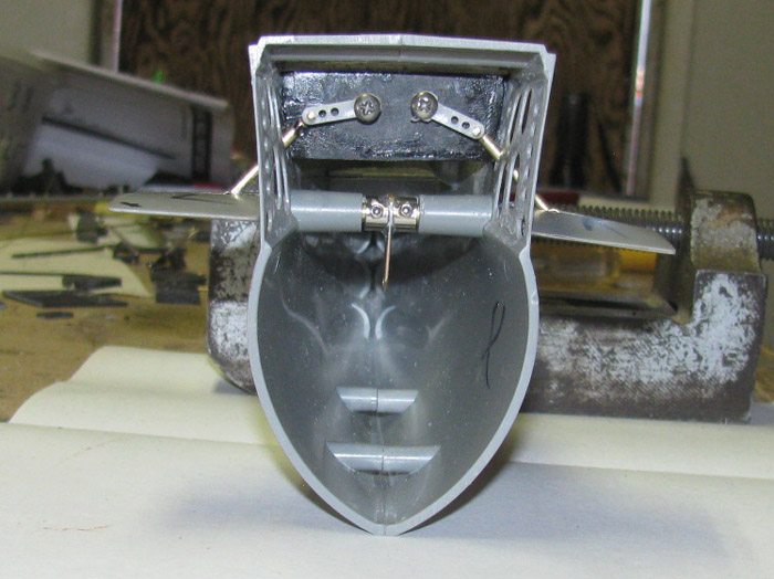
I am working on the rods that lift and lower the planes but I have nothing
worth taking photos of now.
They are long so I have enough to figure out how and where to put the
control horns to make them work.
I made one using a ring that I saw in someone's video.
There was just too much slack, so I need to find a couple of ball links.
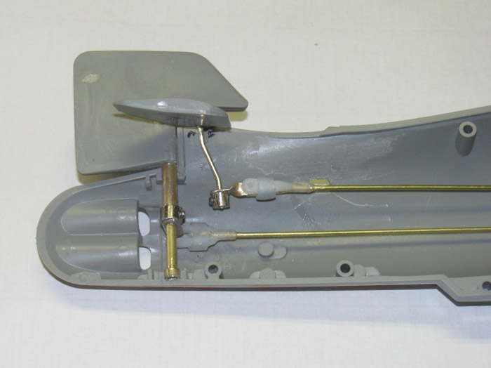
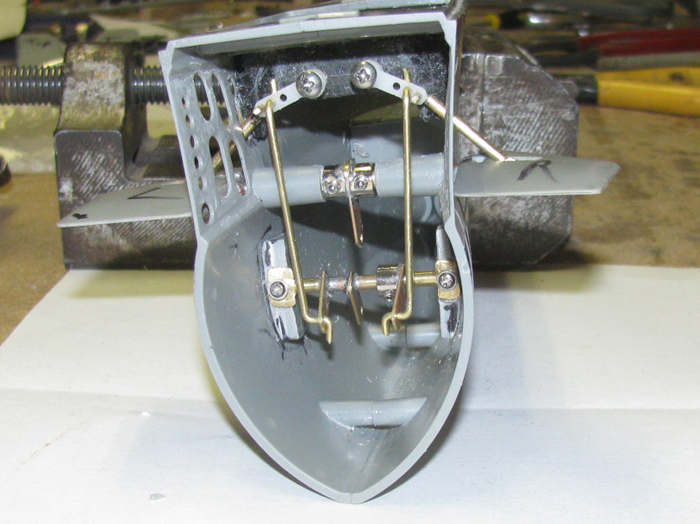
Here the bow planes rotation control rod is in the wheel collar connector.
nothing is permanent yet.
November 24th =================================================
A day has pasted and I had seen.
The doors were cut out and some glazing has been done.
Back to the propeller shaft struts and through hull tube.
Here are all the parts.
I have shaped the ends of 3 of the strut bearings.
The middle one is still to be shaped.
Chucked the tubes in to the drill press and with a fine file I shaped
the ends.
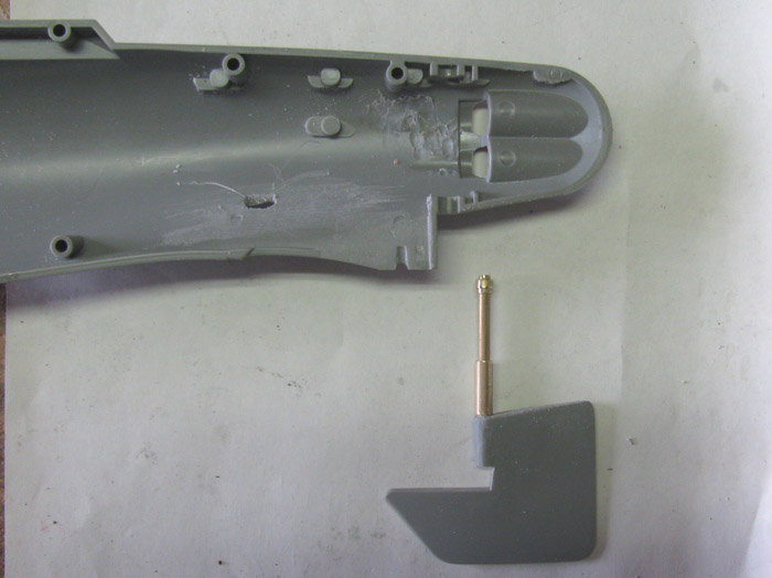
My test propeller shaft is brass.
The shaft will be stainless when I get to the end.
I now have the shaft bearings and through hull tube done.
Except I have not cut the through hull tube to length which I do not
know until I get the rear strut made and mounted.
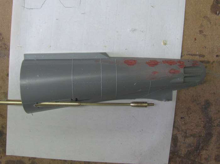
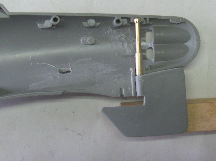
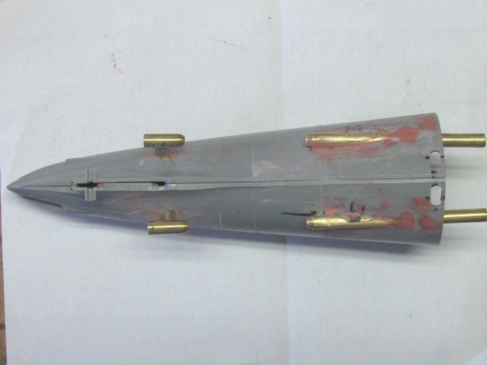
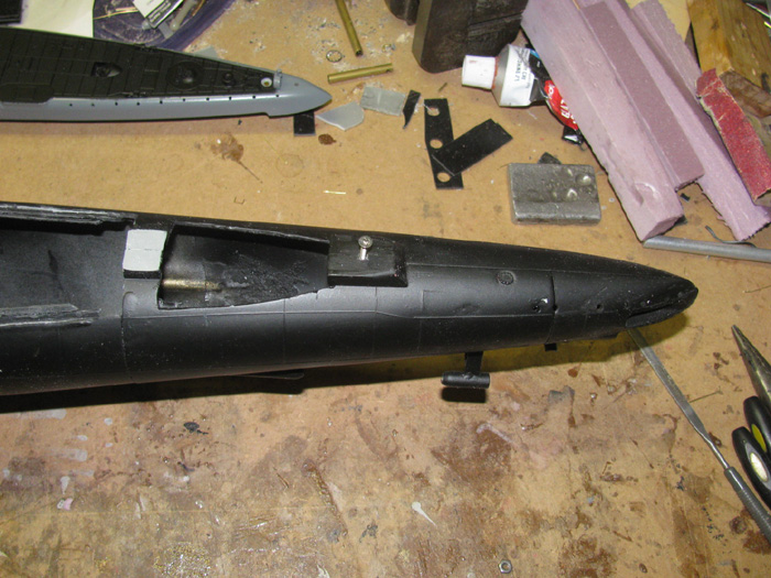
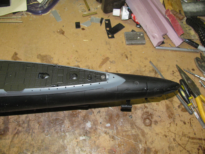
While an making shaft parts, I might as well cut the opening in the
hull for the tube.
Drilled a couple of 1/8" holes in the middle.
Using the dremel, I enlarged the hole by tilting the dremel on it's
side and cutting the plastic away.
When I got close to the guide lines, I went to a small half round file.
The hole is ragged but there will be filler later.
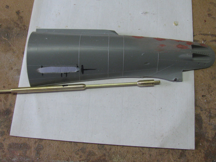
Filed down to the lines and test fitted the through hull tube.
Got the tube to meet the hull at the guide line.
Will do final fit once the rear strut is in and holding the propeller
shaft in the correct line.
November 25th =================================================
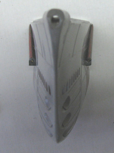
Fitted the bow planes.
cut the through control tubes.
Giving about 3/32" of gap to make sure everything turns.
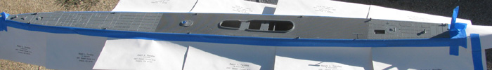
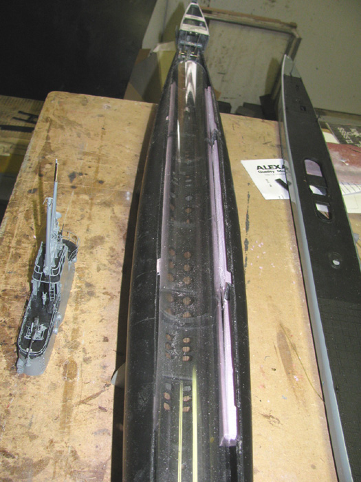
I cut the 2.5" wtc tube at 19" for the GW.
That left me with 29.5" for the Gato.
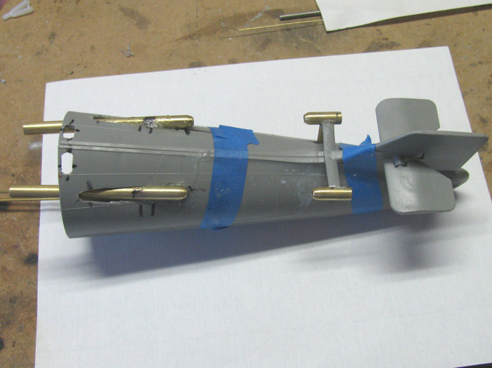
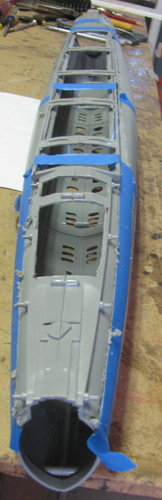
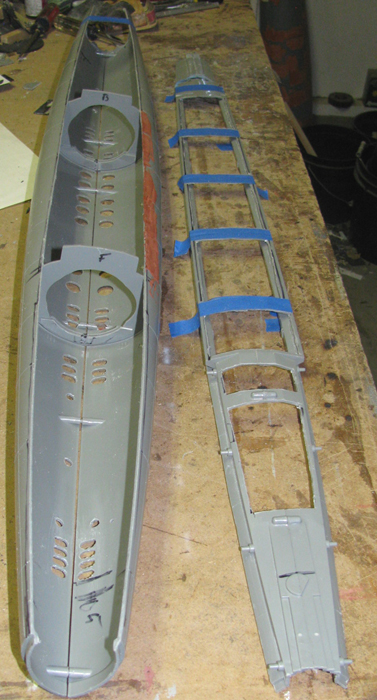
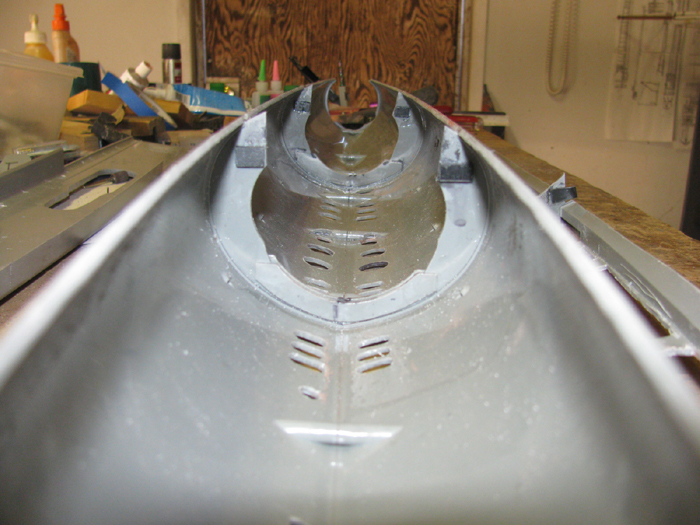
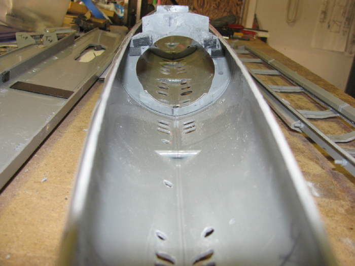
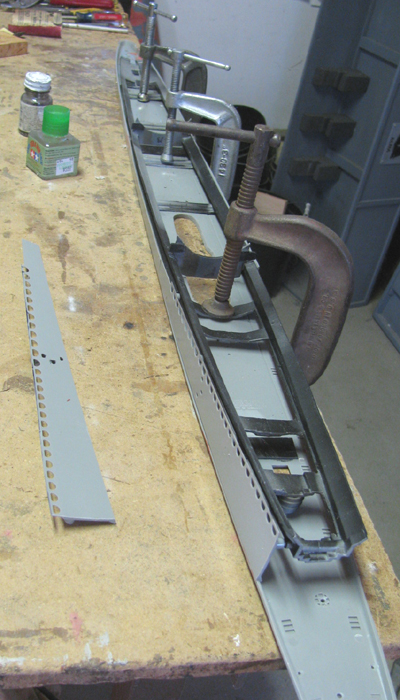
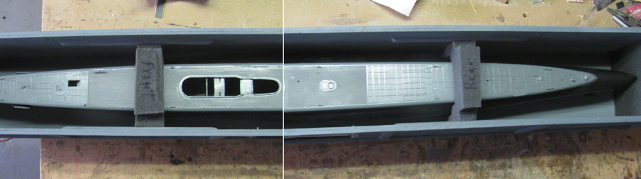
Set the cylinder on the two plastic frames.
Did not require much to get the tube to slide through.
I want the cylinder to sit about 1/8" above the locating pins on the
hull.
This is room for lead weight ballast, later.
Two frames sitting in the hull half.
Wanted to look at the cylinder in the frames for fit.
There is room to move the cylinder forward or backward when I get to
trimming.
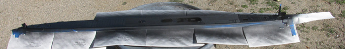
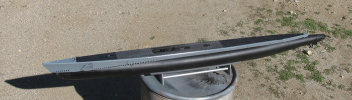
I have not decided where I will cut the hull fro access.
Waterline.
Center of the hull.
Inside the deck fairing where it meets the hull.
I will finish the bow planes installation and the stern rudder, planes
and propeller shafts bow section
before I decide.
I originally thought I would cut it at the center o the hull but now
having talked with a couple of other builder, I may cut it under the deck.
They say the 2.5" cylinder will drop through the opening with no problem
but the linkage may be a bit tight to get to.
So if I finish the bow and stern sections before attaching them to
the hull, I may be able to get to make the connection in a place I can
reach. (fat fingers)
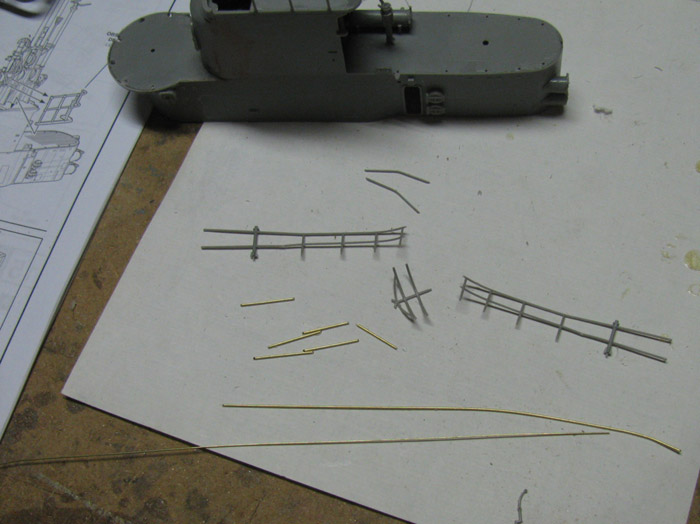
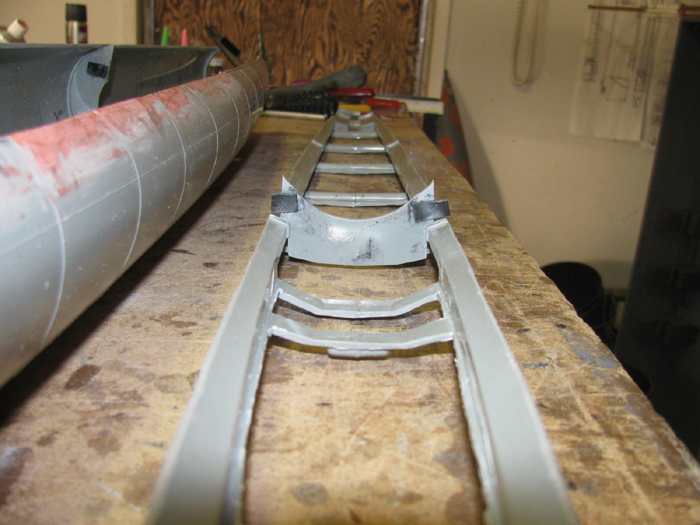
Here I have cut a few parts to start the rear gun deck railing.
I can see I may have to build jig to hold these small parts.
The single part at the bottom is the stanchion.
That is going to be something that needs a jig so I can make 8 of those.
November 26th =================================================
I had a little time this morning.
Out to the shop I went.
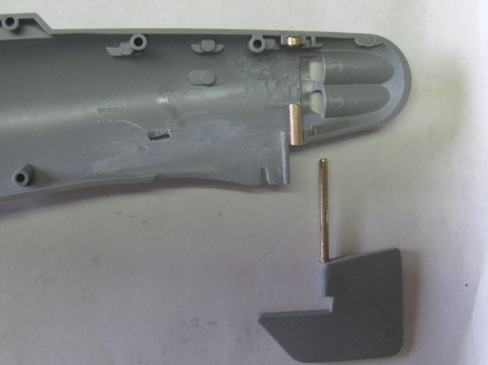
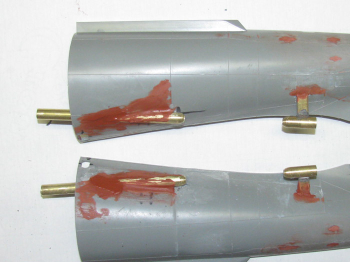
Made two brass rear bearing and strut for the propeller shaft.
Took some brass tubing and flattened tit to make the airfoil strut pieces.
Flattened one end at the strut length and bent the flatten ends.
1 right and 1 left.
Marked the brass bearing housing to locate the strut centers.
Soldered the struts on to the bearing housing.
I drilled a hole in the stern section at the strut location.
Slowly lengthened the hole to accept the brass strut.
Once I get to where I can install the propeller shaft to get the correct
shaft angle, I will then make permanent the rear strut.
The flat bent section of the strut goes through the hull and will be
bent to lay flat on the inside of the hull.
This will get me a bonding surface to take all the load.
Now later in the day after doing real life stuff, I had about 20 minutes
I could spend in the shop.
I went to town and picked up some 3/32" brass tubing while there.
This would be for the bow planes struts.
I cut 2 rings and 2 struts.
The rings will be soldered on to the ends of the struts. (done)
I did not like the slop the connecting pin had and would let the bow
planes move up and down about 1/2" before stopping it.
I see others have used small ball connectors to deal with the slop.
Before I can get to a hobby store that might have those, I thought
I would try this.
I filled the ring with good silicone rubber.
Once it cures completely, I will drill a 1/16" hole through the center
for the hinge pin.
The silicone should keep the pin centered in the ring and also allow
the pin to rotate side to side to let the bow planes rotate for dive and
rise.
More to come on this test.
Got to build a bow plane mechanism .
Then I can figure out where to cut the long strut.
November 27th =================================================
The silicone has cured in the strut rod rings.
Cleaned it up with a knife and file.
Uses a sharpened 1/16" rod to punch a hole through the silicone.
The silicone hole closed up which made it tight on the hinge pin.
Worked on the bow planes.
Finished the assembly of the bow planes.
I used a 1/16" drill bit to lengthen the hinge pin slots to use a longer
pin.
Dry fit all the parts then assembled the bow planes.
Bond the parts.
Here are the 2 planes with the struts in place.
1 is set in to the bow half.
The start of the mechanism to lower and raise the planes started.
Look at the planes raised but not fitted. (have to make the raise and
lower mechanism first)
bow planes lowered.
November 28th =================================================
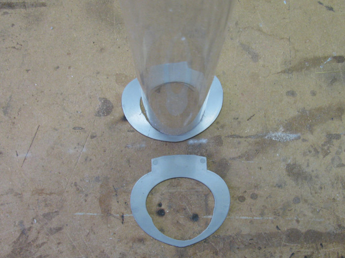
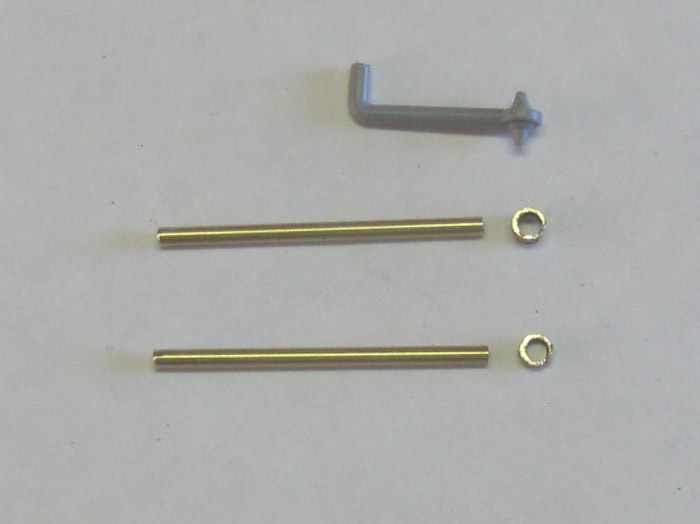
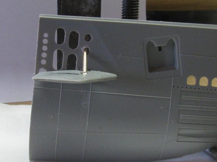
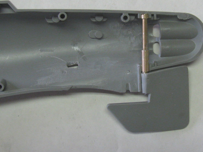
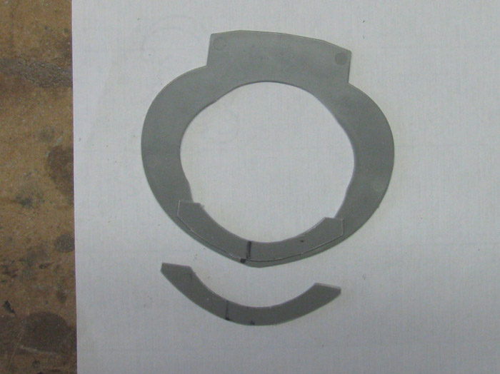
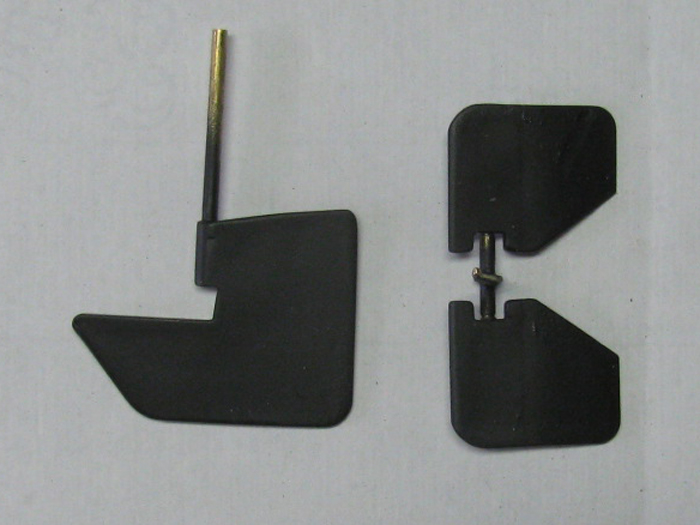
Think I will work on the rudder and the stern planes.
Here is the rudder and the bearing system I plan to use.
The vertical brass tubing is the rudder post.
The 2 little tubing piece at the top and the bottom are shims to size
the locations in the hull to accept the 1/8" brass rudder post.
They will be permanently glued in to the hull.
The small pieces have been glued together and then slipped on to the
rudder post.
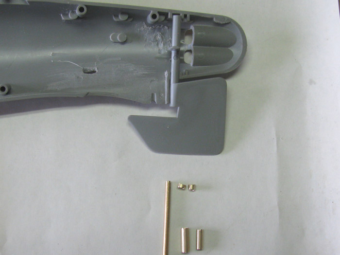
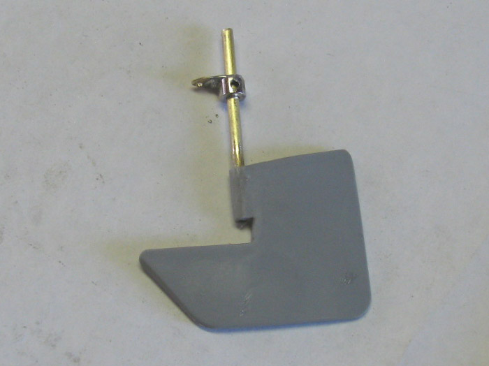
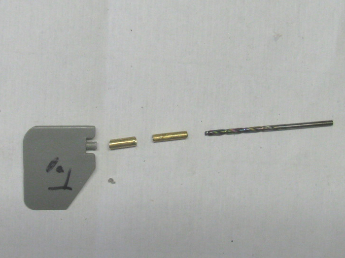
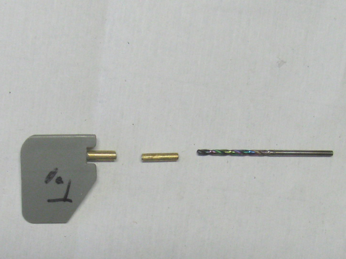
Original rudder.
Getting read to cut the post off flush with the top of the rudder.
Cut rudder post.
New brass 1/8" rudder post tube.
1/16" pilot drill bit.
1/8" drill bit sized for post.
New rudder post with sizing rings slipped on.
Rudder post is not glued in to rudder yet.
I placed a small drop off CA on the bearing rest on the hull.
I place the shims on with my fingers and wiped excess CA off with rag.
Slid rudder post thought the shims to hold them straight.
Hit them with kicker and removed the rudder.
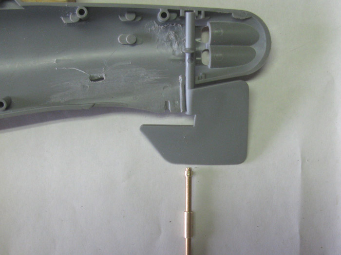
Test fitting of rudder post and trimming to get correct length.
Made a control horn.
1/8" wheel collar with one side sanded for better soldering.
The horn is made form 3/16" brass tubing flatten in vise.
Soldered and drilled for post.
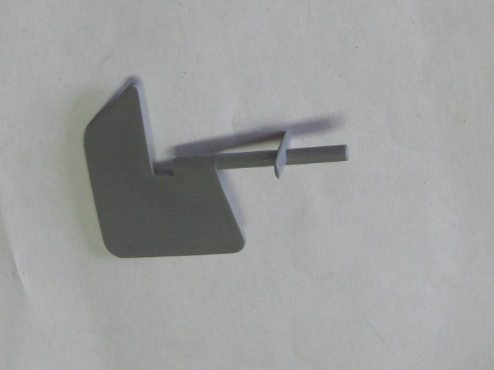
Rudder set in place.
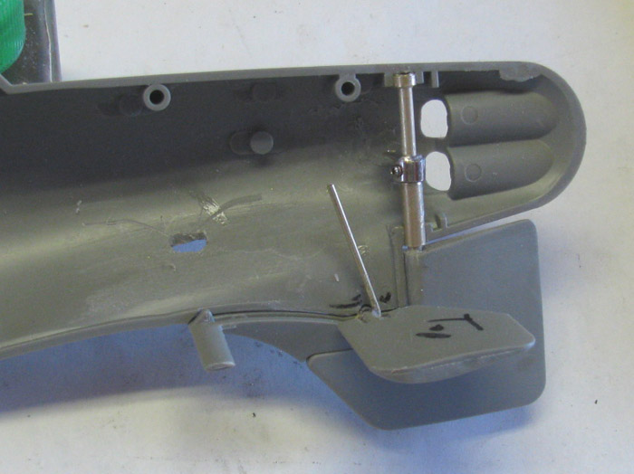
Made a control arm for the rear planes.
1/16" brass rod with a hook bent one end.
About 3/4 the way around.
The rod comes up on the rear side of the planes shaft.
Fits through slot in skag.
Glued to the planes shaft after twisting the hook around the shaft.
I should mention, I ground off the rudder post mounting sockets on both
sides of the hull.
They were about where the top of the planes control rod stops.
Also ground off 1 propeller guard socket near the same place as the
other socket I removed.
I probably could have left this socket.
The planes control rod has not been cut to size yet.
November 30th =================================================
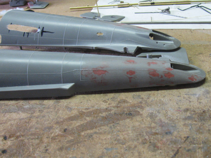
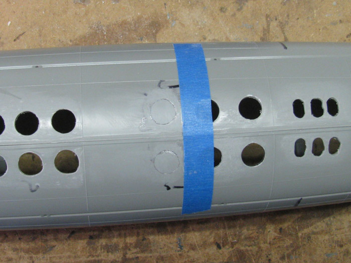
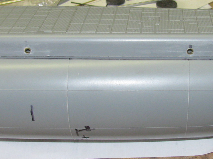
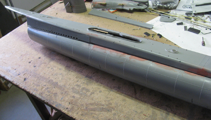
After removing the prop guard hull brackets and glazing the holes, there
was sanding to smooth the glaze down.
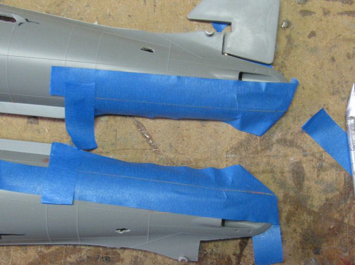
Doing this removed some of the weld lines.
I read Tom's Gato build and he too had removed weld lines.
He also put them back using baking soda and CA.
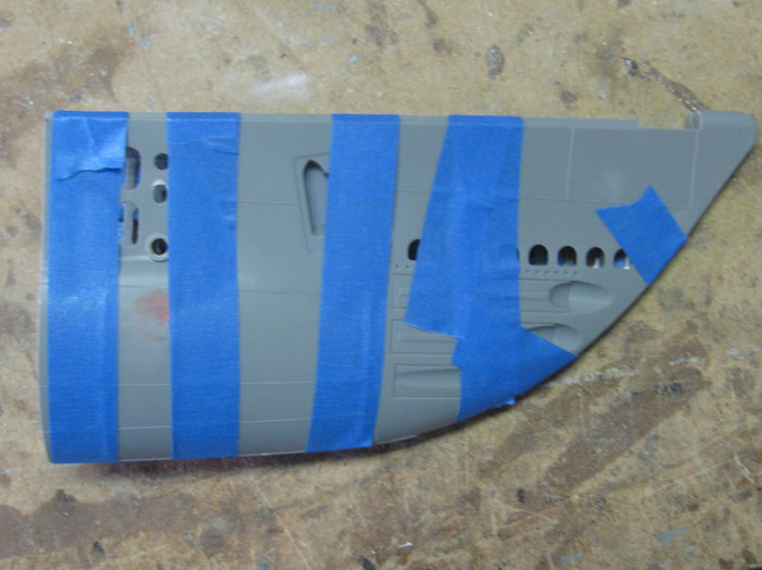
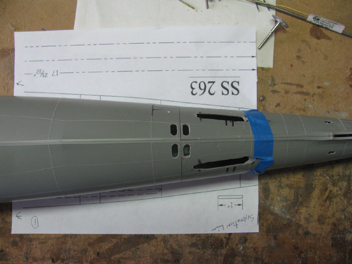
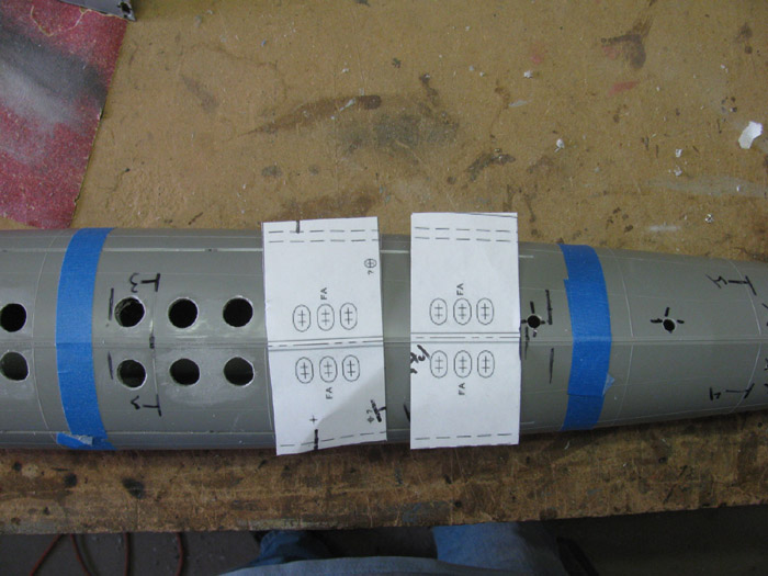
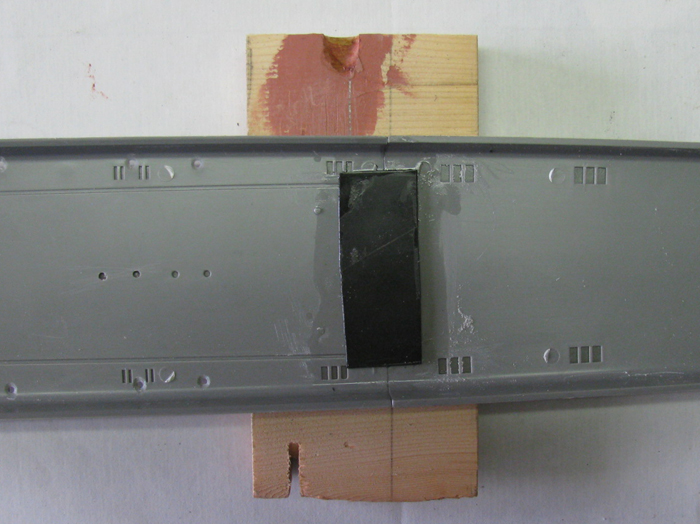
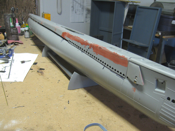
Here, I have taped off the replacement weld lines.
There is a small open space between the 2 tape pieces.
I put baking soda in the space.
Using thin CA, I covered the baking soda.
I let set while I moved on to other things.
To keep from jumping around too much, I will show the finished weld
lines after sanding using the tape for the thickness of the welding.
Thanks, Tom.
It worked really well.
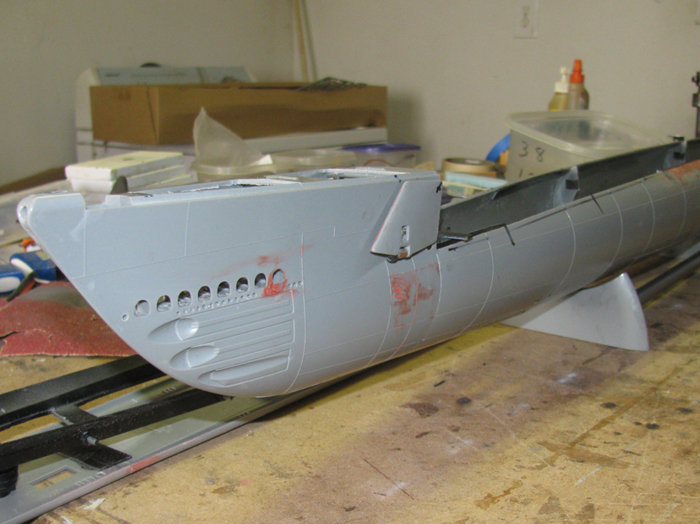
The line replaces goes above the torpedo door.
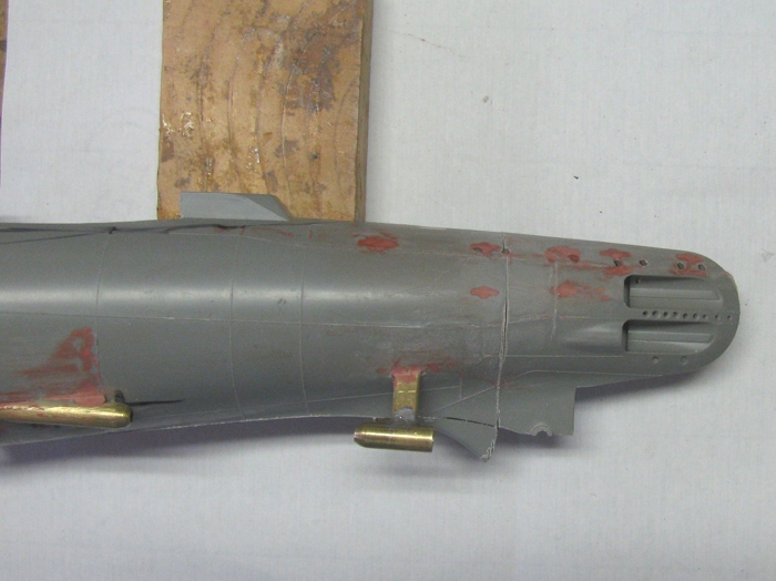
Bottom hull, the line is below the bottom torpedo door..
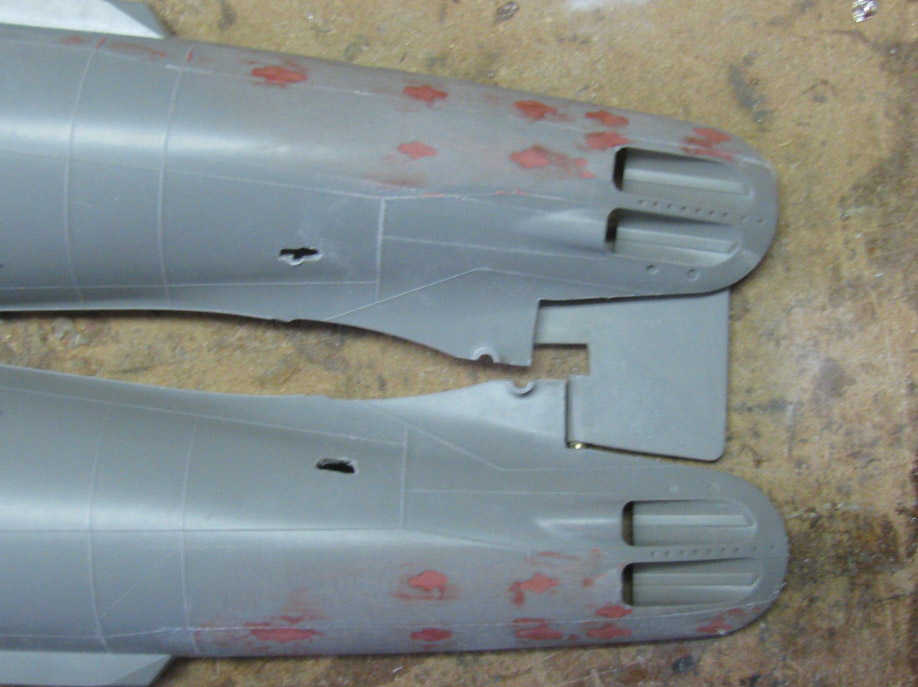
Can see the line better here.
Center of bottom hull half.
Got a couple more lines to do.
Time to join the 2 bow sections.
I decided to d this now because I tried to work on the bow planes lower,
rise mechanism and I could not hold it in place while trying to measure
for the control horns.
Looking at Tom's build, I saw I could join the bow sections and cut
the top out and would get access to work on the bow planes.
I had already glue the indexing pins to one side of the bow.
Applied glue to the pins and the edges.
Put the 2 halves together and taped to hold tight together.
I moved on to deck while the glue cured.
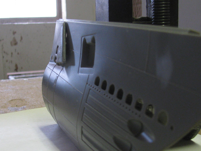
Back to the bow section.
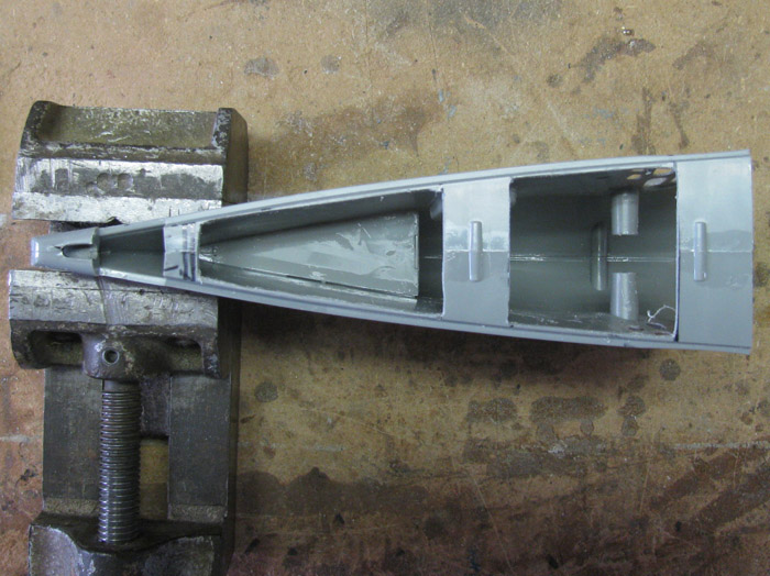
I removed the tape and then marked the top of the bow section where
I wanted to remove plastic.
The vise is not tight but only holding the bow section for the photos.
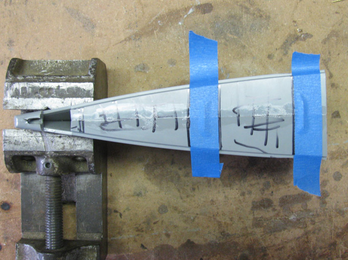
Using the Dremel saw blade and a could of files, I ended up with the
opening in the bow section top.
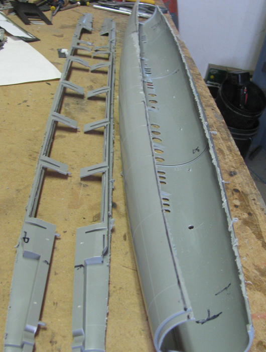
Now I can reach in to fit the bow planes mechanism.
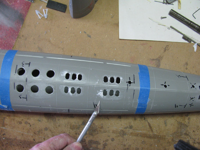
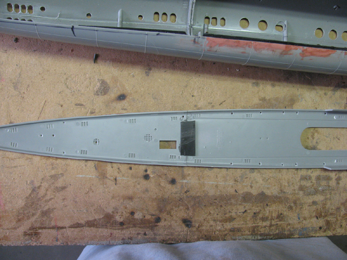
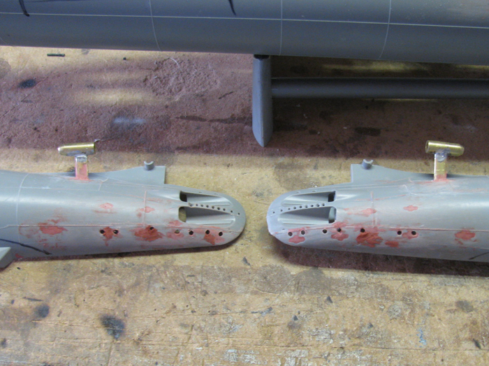
Before I glue the center hull sections together, I need to cut in all
the flood ports.
Here are 2 on the stern section and 2 on the center hull section.
Marked and drilled a location hole where all the flood port opens are.
Now comes the long job of cutting and filing all those holes.
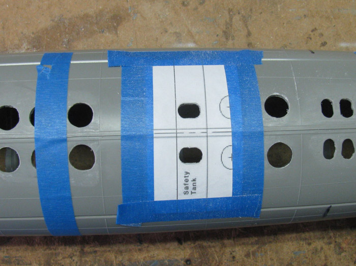
Tom, I think I am going to use your "Milk" trick to put the flood holes
templates on the hull.
=============
Later in the day.
I have done 1 more weld line on each stern half.
1 more to go that is about 1/2" long.
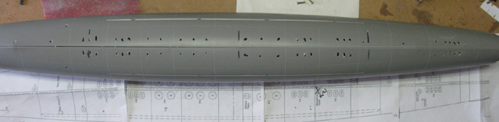
I have drilled all the round flood holes.
I have enlarged the oval holes.
I have laid out the paper templates of the flood holes from the stern
joint seam going forward.
I have cut them in to small 3 or 6 holes per sheet so they lay flat
on the hull and not buckled.
I have built the conning tower big gun.
Not sure if I will build the small machine gun or run as if it was
in the stowed locker.
Things are going along fine.
I am building small parts and assemblies and not looking at the big
picture except to see where I should go next in the sequence.
I can see washing the plastic parts and painting in the near future.
December 1st =================================================
Got up and felt good.
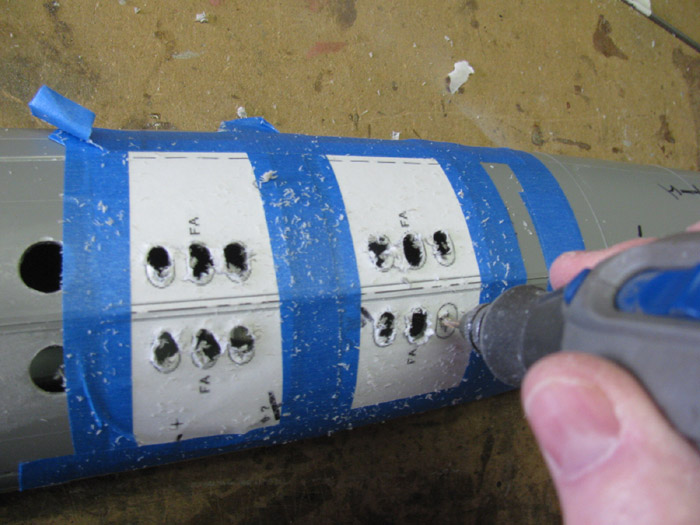
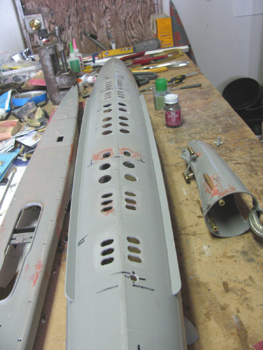
So, I will attack the flood holes.
Here you can see I am moving right along.
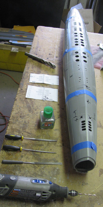
Before I finish, I will try to explain how I did this.
Tom's build said something about using Milk to hold the paper pattern
on the hull but also said it did not do well..
He mentioned a few other tried that did about the same.
Having thought about it, I thought I would try using the method I use
to make frames and other plastic parts.
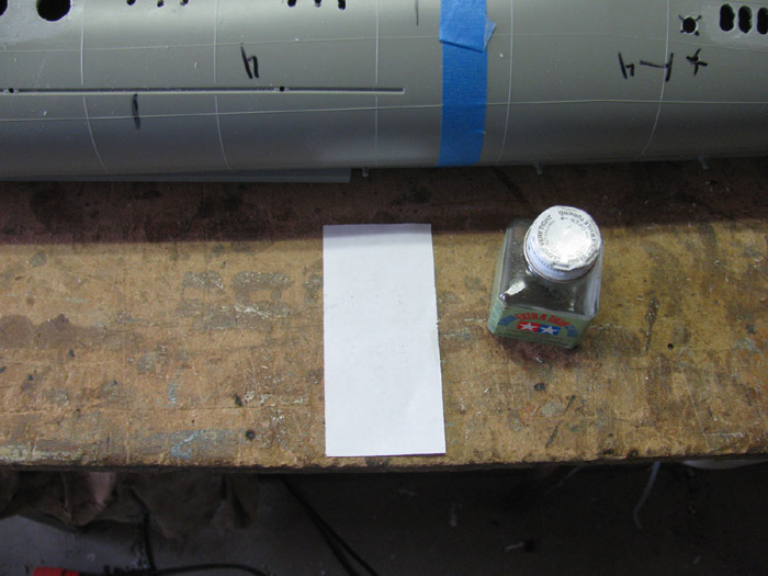
I got the middle deck and turned it upside down on the bench.
I took a scrape piece of paper and tested on the underside in case
it failed.
I could sand it off with out damaging the boat.
I printed out the flood hole pattern to scale.
Took 4 sheets of paper to get the overlap I need to align them.
I cut the paper using the weld lines marked on the image.
This is after laying the paper pattern on the hull to make sure which
weld lines to use.
I started at the stern break line.
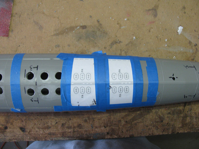
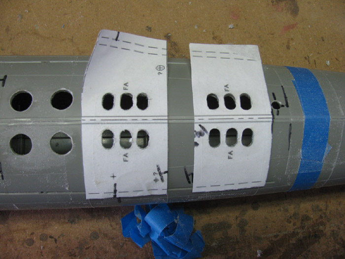
Now to what I did.
I did 2 flood hole sections at a time.
Here I am placing the patterns on the hull to make sure where they
go.
Remember I drilled small holes using the full pattern. (I did not need
to do that)
Starting with one of the pattern pieces, I turn it up side down making
sure it is orientated correctly to the hull.
Have cement handy.
I wet the paper with cement and the lines on the pattern show through
so I can see where they are.
Wet the pattern, covering the lines of the holes going about 1/4" outside
the lines.
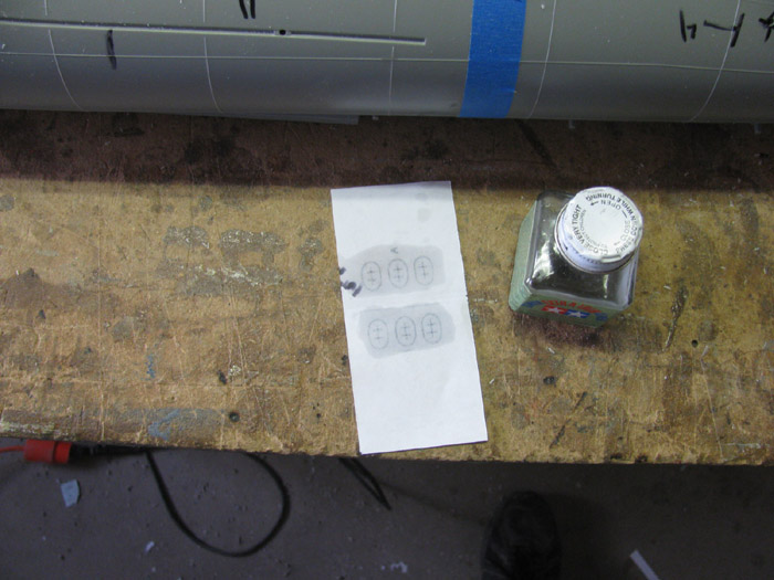
After covering all the lines, I do a quick covering again to make it
wet.
The cement soaks in fast.
Once the second coat is on, lift the paper and place it on the hull
with the cement down and in contact with the hull.
Line it up with the keel center line.
Using my finger nail, I press the paper in tight against the keel.
Press the paper down on the hull and rub the paper making it warm.
Tape down all 4 sides and rub paper again to make sure it does not
move.
Do the same for the second piece.
Let sit for 15 to 30 minutes.
Using my Dremel with a 1/8" bit, I drill in to the hull and then route
out the plastic almost to the line.
I will use a couple of files to finish to the line.
I do not use the roto cutter.
Not enough control.
This is after the filing and deburring.
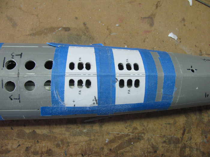
Remove the tape.
Remove the paper.
Pull the paper tight way from the holes and lift gently.
It will most likely break at the mid point.
Lift from the other side.
You can pick the little pieces of paper off with your fingers.
After removing the paper with my fingers, I used an Exacto knife to
scrape any remain paper off.
Sand with wet/dry sand paper to clean the rest off (180 grit is what
is on my beach. It is well used)
With the flood holes done, it's time to get serious.
Cut the top of the hull out.
This is were I stopped.
Fingers where cramping up.
Can not afford mistakes.
I real need to look at some other builds to see where they did the
cutting.
December 2nd =================================================
Today has turned out to be one of those jumping around days.
My plan for today was more plastic holes in the deck.
Found some close up photos showing the layout of the holes at the deck
stern.
But when I first got up, I started having thoughts.
So the plan changed.
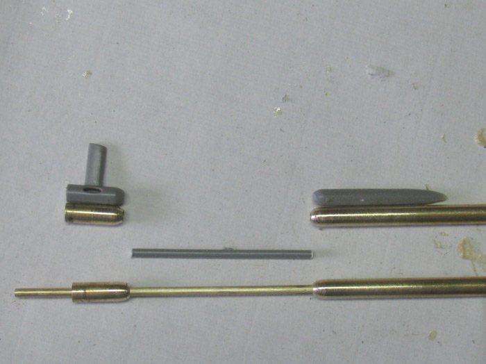
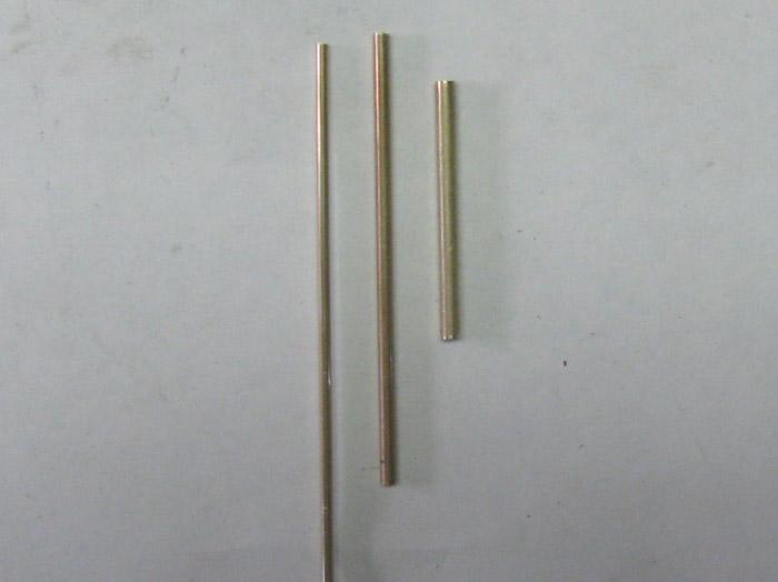
I picked some small pieces of tubing.
3 sizes.
This will be part of the bow planes operating system.
Not the bow planes them self but more linkage to get to the bow planes.
This idea came from looking a Darrin's big sub about a year or so ago.
(most likely longer)
What this is is to make it easier to get to the linkage for adjusting
and setup.
Some measuring and cutting.
9 brass parts. (there are 2 plastic parts I have not made yet.
Top are 2 hinge peg brackets.
Next is a single long tube which will be the hinge pin.
2 short tubes go over the hinge pin and will rotate.
These will have the control rod horns soldered to them. (once
I start installing it all and get the correct angles)
4 flatten brass tubes to make the horns. (already drilled)
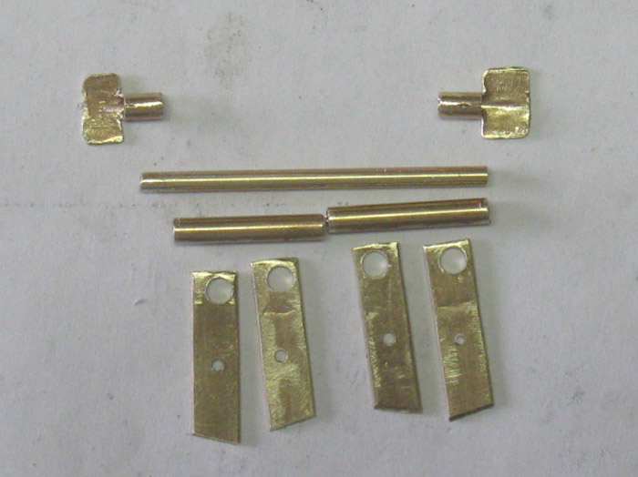
All the parts assemble to get a look. (dry fit)
More work needs to be done after the bow planes mechanism is installed
in the bow.
This unit will be low in the hull below the bow planes.
The horns where left long for now.
1 horn will raise and lower the planes and 1 will rotate the bow planes
for dive and rise.
The unit is upside down on the table.
The end brackets will be screwed with 1 screw each side on to plastic
blocks so I can remove the unit to work on it out of the boat.
Time to jump.
Made up the control rods for the rudder and stern planes.
I have an allen wrench mounted on a length of brass tubing to reach
in the stern.
But I think I can reach the nylon clevis to open it to remove the control
rod. (?? 2 options))
I did turn the planes wheel collar facing the back and I can reach
it through the torpedo tube opening.
Turns out, I can not use the 4 torpedo tube doors.
They interfere with the rudder horn.
Held the parts in place and worked the control rods to check clearances
and how much movement I have.
Rudder all the way to touching the planes.
The planes have about 30 degrees down and about 35 degree up. (more
than enough)
==========
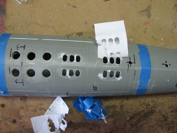
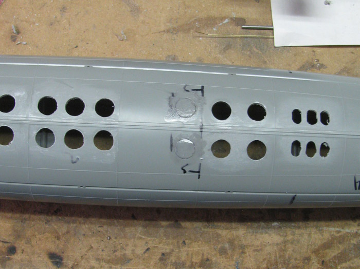
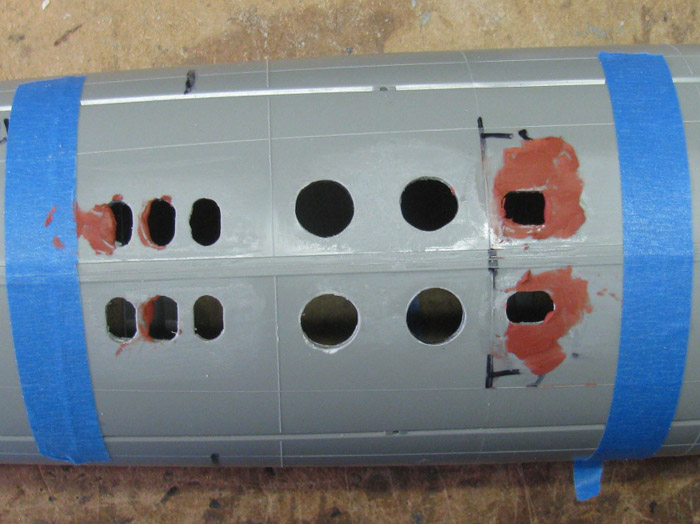
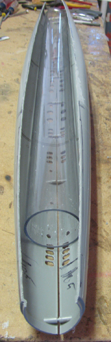
Looking over the flood holes, I see I made a mistake.
I made 2 large holes where there should have been 2 small holes.
In the following photo, there is a number 3 on the hull between 2 lines.
That hole should be the size of the paper holes but turned 90 degrees.
I will have to fix that.
Fill the hole and make new small holes. probably make the holes in
the repair plastic first.
==================
Jump, again.
Held the stern against the middle hull to see how the propeller shaft
strut and tube bearing sit.
The left side lined up to the strut and the hole in the hull.
Needed a plastic shim the thickness of the hull to hold the front end
of the through hull tube bear away from the inside hull so the middle hull
joint will fit under the bearing tube.
Tapes a piece of shaped plastic in the stern section where the joint
will be.
Taped the long tube in place and then lined up the rear tube bearing
to the stern planes using the propeller shaft as my guide.
I placed a flat piece of plastic on the stern plane holding it with
a spring clamp.
The propeller shaft rested on the plastic making the shaft inline with
the stern planes.
Need 4 hands to do this so help with tape and spring clamp did it.
Got my medium thick CA out and the kicker.
A drop on the rear strut at the hull where the strut goes through the
hull. KICKED IT.
Made sure the little plastic shim was still in place and I lined up
the long tube with the indexing marks I I put on the hull to get the end
in the right place and centers to the fore and aft lines.
Medium thick CA on a .030" wire and drug it along the tube/hull seam.
KICKED IT.
Made sure the propeller shaft turned freely. Yep.
Drooped a little CA on the opposite side of each joint and KICKED IT.
Removed propeller shaft. Only have 1 right now.
----
Did the other side the same way.
I had to break the long tube loose and line it up again.
It did not turn easily.
Line everything up again and a drop of CA.
Shaft turned nicely now.
CA the other side of the parts and You guessed it. KICKED IT.
The CA is to hold all the parts in place.
I will CA and baking soda the gaps, tomorrow.
Then I will finish by placing a plastic piece inside the hull that
will be a block with a hole in it for the tubing.
I have some old silk span that I will put a couple of layers over the
tube in the hull to make sure it holds.
Fill the outside with glaze and shape it to match the hull.
The propeller shafts line up to the center of the stern planes.
Once this is completed, I will measure the placement of the cylinder
to see if I need to cut some of the long tube off.
Maybe an inch but maybe not.
December 3rd =================================================
Photo of the repaired holes.
Sanded flush with hull.
Paper pattern in place and new holes cut in.
Time to do a little glazing.
This all that is needed.
Sanding tomorrow.
December 4th =================================================
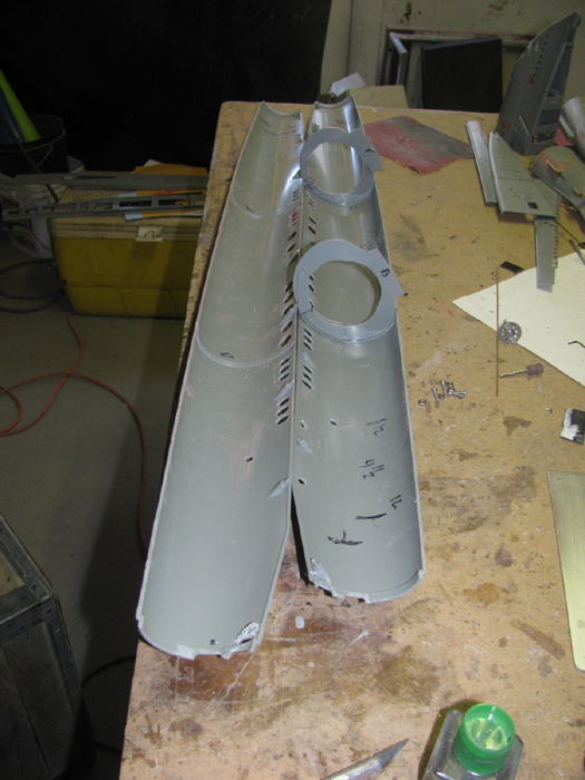
Worked on the 2 stern sections.
Filed and sanded to get the through hull propeller shaft housing cleaned
up and the hull.
This took a while.
CA with baking soda is very hard material to get smooth and shaped.
Worked on the skag gap.
Placed a shaped piece of plastic in the slop so I and use it for a
retaining screw later.
Going to make the back half to the skag removable to pull the dive
planes out.
Opened up 1 rear torpedo door.
This will allow me to put the doors in the hull.
I can get to the allen screw on the rudder with a standard length wrench.
Now they need to be glazed to finish getting the shape right.
Sanded the repaired and flood holes.
Then applied plastic cement to harden it.
While I had the middle hull sections on the bench, I dropped the cylinder
in.
Something was not right.
I had cut the 2 frames to hold the cylinder just above the hull index
pins.
The cylinder is 29" long and with the frames on does not sit down low
enough in the hull.
Using just one hull half, I used scrap plastic to lift the cylinder
up.
I had a reference, from where I don't remember, that the cylinder would
sit about 10..5" back from the bow end.
Marked the inside of the hull and placed the cylinder at that mark.
I had to raise the cylinder up 3/16" higher than the indexing pins.
I files the 2 frames on the indies top so the cylinder would go up.
Measured down through the cuts in the top of the hull to get the cylinder
level in there.
Attached this slowly.
Once I got the cylinder to fit in the hull and level, I got measurements
to make new frame saddles inserts.
Here is 1 frame with 1 new saddle on one side and a second saddle for
the other side.
I doubled up the frames.
Did the same for the other frame.
These new saddles are just to support the bottom of the cylinder.
The cylinder fits and can be moved about 1" at the bow and about 1.5"
at the stern.
When I place it will depend on the linkage connections.
===================
Tomorrow, I may be able to put the stern section halves together.
December 5th =================================================
When I assembled the bow planes, I noticed the planes did not retract
up tight to the hull at the front edge.
At that time I decided to live with it.
Well, as time goes on and I am now working on the stern and bow to
get the control rods ion place and work smoothly, I find I can not live
with the bow planes not being tight.
I knew that a small angle was needed on the hinge to get this to happen.
I thought I had done this. ? ? ?
Reading Tom's Gato build he added a drawing showing how the angle should
be.
Got out to the shop and turned on the heat. (temperature in the shop
was 38 F)
Took a few minutes to get warm enough to work.
First, I was going to take on the dive planes.
I cut the front hinge off.
The one where you can see the hinge pin.
Removed all the plastic from the pin and then pulled the pin and strut
out of the bow plane.
Cleaned up the hinge pin of glue and plastic.
I put the planes back together and held it by hand.
Traced an outline around the plane and strut.
Remove the strut and turned it over.
Put it over the tracing and found I did have the angle when I built
it.
\I just happen to put it in reversed.
Did the same to the other bow plane.
Guess what.
I had reversed it as well.
Made 2 plastic pieces to cover the hinge pin.
Cemented the pin covers in place.
While these 2 parts cured, I started making parts for the retraction
mechanism.
Here the planes are seen with the pin caps and the start of parts for
the retract.
Bow planes now sit tight to the hull.
More work to be done on the retract mechanism.
It has warmed up in the shop, so I thought I would do some glazing on
the stern sections.
I glazed around the shaft bearing housings.
Now that I have done that, I took the stern sections in to the house
to cure.
December 8th =================================================
Filed and sanded final glazing.
I need to put the weld lines back on.
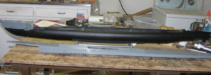
I test fit the stern to the main hull.
Then I test fit the cylinder in one half the hull and put the stern
on.
Looks like I need to cut about 3/4" off the propeller tubes.
This will leave room for the Dog Bone connectors.
Finished parts for the bow planes retract.
Here the planes are up.
Here the planes are out.
Testing shows it works smoothly and without binding. (yea)
The horns have over travel so there is plenty to work with when trimming.
The holes in the hull where the struts pass through were enlarged vertically.
The horns have 3 holes.
The farthest out is for the struts.
The other 2 so there is adjustment on the throw.
This devise will be mounted in the hull below the bow plane mechanism.
There will be a brass rod from each of the 2 bow plane horns down to
it's own brass horn.
There will ne only 1 brass horn going to the servo control rod.
This devise will mount using 2 small screws on to plastic blocks in
the hull.
I will use the hole in the bow planes that gives the best movement
with the most force.
I drilled more holes in the deck pieces.
Now have exhaust holes in the sides of the deck.
Test fit the cylinder in the hull with the stern and bow taped in place.
Looks like I may cut 1" off so there is room for the boot control rod
seals.
This still gives me 28".
December 9th =================================================
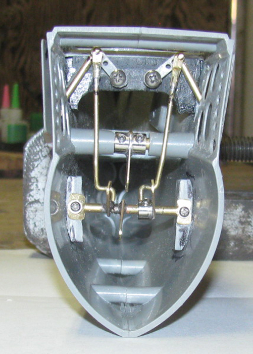
This assembly will be mounted under the bow planes retract mechanism.
The control rod in the photo will go back to the servo in the cylinder.
The other 2 horns go up to the bow planes retract horns.
The plastic end pieces will be bonded under the bow planes rotation
cross tube.
The 2 horns will reach forward past the rotation tube.
The location for the 2 plastic blocks has been made.
The plastic blocks have been installed and are currently curing.
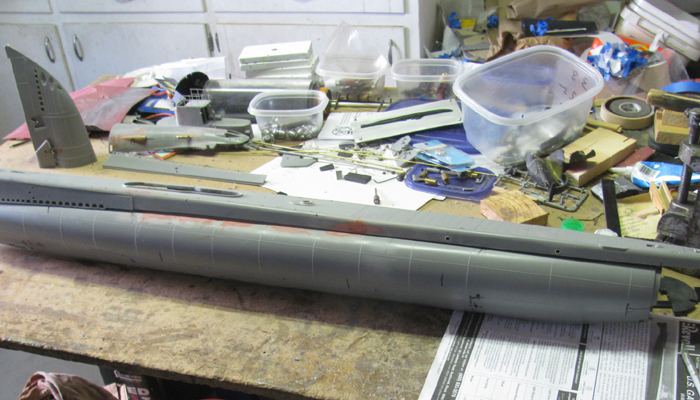
While holding pressure on the blocks to get them to stay in place, I
was looking around and I need to clean off the bench.
It is so cluttered, I only have access to 1/4 of the table top.
I have the conning tower, 2 guns & mounts, all 3 pieces of the
deck, the box with parts and all the tools, glues, small clamps and parts
for the ALMA and another project.
I think a bit of clean up is called for before I can go on.
There is no room for the Skipjack which I need to make a small repair
to so the hull halves sit tight together.
Oh and I need to repair a window handle in my truck.
Not a big project.
Fitted the other side last year.
December 10th =================================================
Did not get much time in the shop.
Here is what I got done.
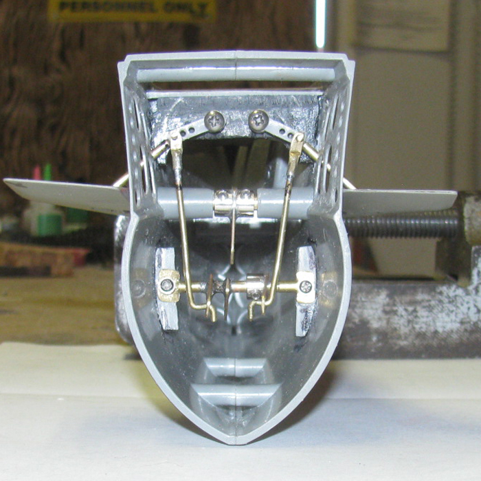
Bow planes mechanism completed.
There was some binding at first but I found it and changed the parts.
The 2 vertical rods where in front of the planes rotate shaft.
As the rods moved forward and aft, they hit the shaft as the rods reached
top and bottom of the throw.
Did some bending of the rods and finally gave up.
There was no way to adjust one or the other if the rods where not exact
to length.
Did some measuring and found I could run the rods to the back side of
the shaft.
and turn the lower horn assembly over making the horns move to the
back. Reference the hull. Back...Front)
Now the rods are straight and the rod on the right has a wheel collar
so I can adjust the plane to match the other one.
Planes up for surface running.
Planes down for dive.
I still need to work on the right plane as the silicone bushing is not
doing it's part.
Will need to make something new. to put pressure down on the hinge
pin.
Cut the propeller shaft housings off 3/4".
New brass tubing to size for shaft have been made and installed.
December 11th =================================================
I started the morning, making adjustments to the bow planes mechanism.
This took a couple of minutes.
A little trimming of the hull hole the strut passes through.
On to the stern sections.
After cutting the shaft tubes, I need to make new brass tubing pieces
to insert in to the large tube.
Got them in and then checked the shaft alignment through the 3 supports.
Requires some filing to get the new bearing to line up.
One side took just a little work.
The other took probably 20 minutes to get it lined up and smooth.
I like my propeller shafts to spin freely by hand.
I looked around and thought about cleaning up the bench.
Moves some tools to the right end of the table.
Then I could see, I had room to start assembling the deck sections.
To decide where to cut the hull, I need the 2 back sections of the
deck to do the measuring to see how the cylinder will fit thorough the
open after the cut.
I started by putting a piece of sheet plastic on the under side of the
middle deck.
Let that cure for a few minutes.
Tom's build pointed out that the deck is not flat.
I placed the decks on the hull looked down the deck.
Yep there is a 1.4" rise from end to end of the rear 2 sections.
Using wooden blocks, I set up a surface to put the decks on while the
glue cures.
Glued and held down until the glue set.
While the deck is off the hull, it is time to make the 4 exhaust ports
in the sides of the deck.
Here I have cut brass tubing to make the ports.
Drilled the holes to accept the brass tubing pieces.
2 ports in place.
Set the deck on to get a look.
WARNING ! ! !
Today is the day I have decided how I want to cut the hull for access.
I have decided to not cut the hull at the water
line which has been my plan since I started.
But looking at Tom's build I did some measuring
and found that his cut under the deck will work with the 2.5" WTC and the
length I want.
Here goes.
If you get squeamish when cutting in to the hull
full length, you may want to skip this section.
Taped the 2 hull halves together.
Set the deck in place.
Marked the outline of the deck with a black marker.
(wanted a big line to see where not to cut)
Using the diamond saw blade, I will cut 3/16"
above the marker line.
Look away .... I am going to cut this free hand.
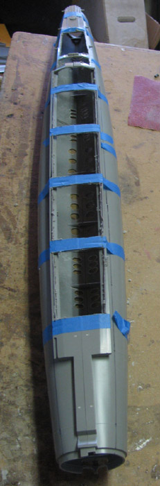
First photo the hull has been cut.
Second photo the top of the hull has bee removed.
Have not started removing the melted plastic
at this point.
Did a quick removal of the melted plastic but not to a finished edge.
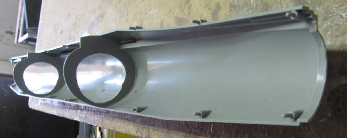
Dropped the WTC in to the lower hull halves.
At the bottom of the hull you can see the 2 marks I have made to indicate
where I want the front of WTC to sit between.
The opening is wide enough that the long cylinder drops right in.
Looks like there is room to add the end caps and still drop in.
I can cut 1" off the cylinder if needed.
Now for the time consuming part.
Clean up and make straight the cut edges.
Going to take my time and do short section and not try to do it all
at once.
I was out in the shop, again.
Thought I would get after the edges and see how much work I am in for.
Got my favorite wooden sanding block and wrapped it with 80 grit sand
paper.
Not to worry, my 80 grit sand paper is well used and is more like 200
grit.
There is one edge that is still in good shape.
I sighted down the cut edge to look for high spots.
Just a few.
These I went after with the Dremel and a 1/4" sanding drum.
Before the sanding block., I cut all the melted plastic off and hit
all with a file.
Now the sanding block.
I started at 12:55pm.
This went a lot faster than I thought it would.
Not only did I get the 2 hull pieces sanded.
I also got the 2 upper hull pieces sanded.
Once I was happy with it, though there could be more sanding after the
hull halves are joined, I joined the 2 upper halves together.
This is how I left it when I closed up the shop.
December 12th =================================================
Sanded the glazed areas down to a smooth hull.
I can see a few low spots.
Filled the again and set aside to cure.
Well, it happened again.
Was looking at the bow and saw where I could make a little change and
get more advantage out of the retract control rod.
Disassembled the parts after making a mark on each control rod about
1/4" back from the Z bend.
Cut the Z bend off and made a couple of small parts.
Using brass tubing that the 1/16" brass rod will go in, I flattened
the end.
Punched it and drilled a 1/16" hole in the flattened area.
In the photo below you can see the part at the top places over the
strut end sticking through the horn.
This moved the control rod out 1 more hole.
Soldered the new end to the control rod.
Made the second one the same. Almost. Little difference in length but
a small bind in the rod fixed that.
Planes up.
Planes down.
I may remake the lower horn assembly.
I may make the horns a little longer for more throw.
I measured everything and now to make a drawing.
I may enlarge the photo and draw lines on it and label them with a
corresponding list of parts and dimensions.
December 13th =================================================
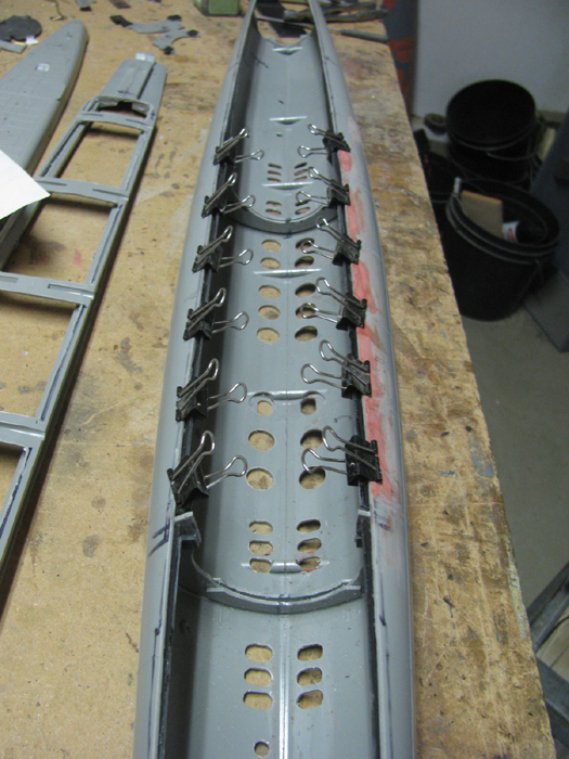
The time has come to join the two hull halves together.
To get the upper deck mounted requires the lower hull to be complete.
Got to get the cylinder saddles cut and in place.
The deck needs tabs to hold it up once the saddles are cut.
Installed the 2 frames to one side.
Put the cement bond to each side and then put them together.
Tape to hold tight while holding by hand to squeeze the parts together
watching he seams for the cement lifting up.
Once the cement stops squeezing out, I can let go of the parts.
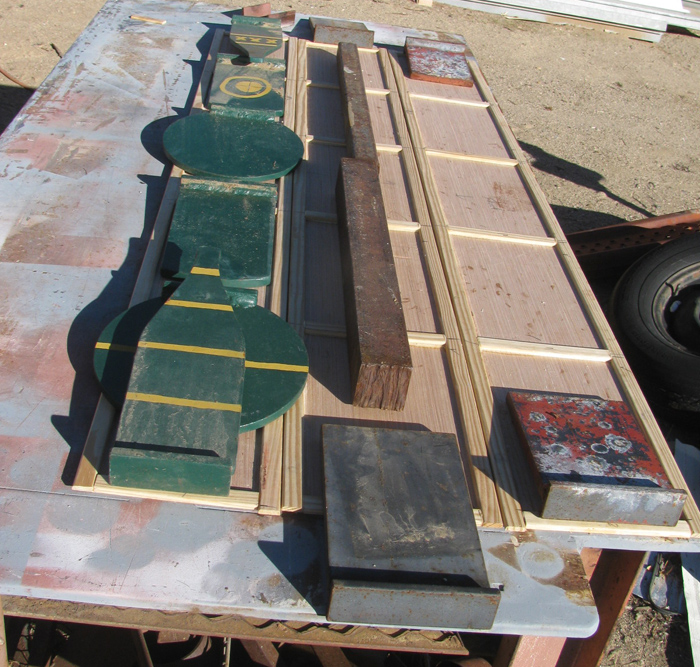
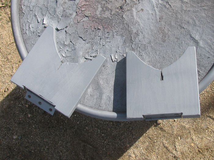
While in the shop, I thought I would work on the transportation box
emblem.
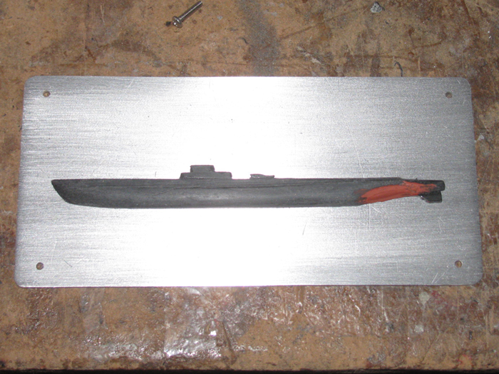
Basic hull shaped and glazed to correct a gouge.
When I was making these for the other boats, I made extra aluminum plates.
Once I get the hull glaze sanded out, I will mount the hull on the plate.
Then I can start making some of the parts that go on top of the conning
tower.
==================
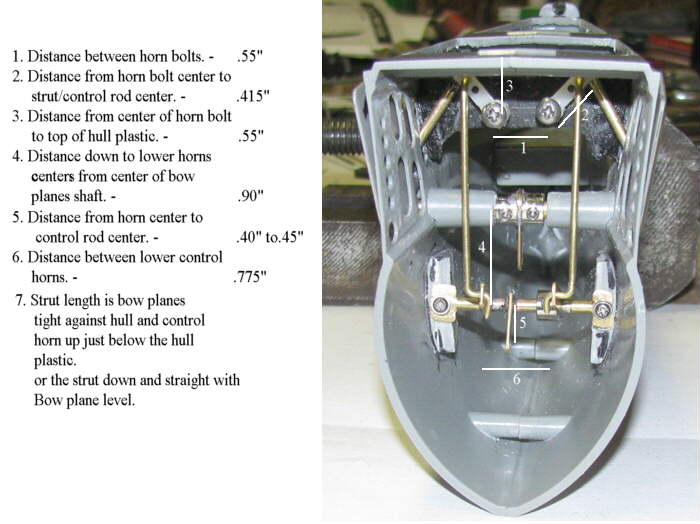
Here are the number my Bow Planes retract mechanism.
Finished out my day cutting the 2 frames and making index blocks to
hold the deck under frame at the correct height.
Here you can see 2 plastic blocks on the front frame.
The placement was decided after holding the cut frame piece in place
and seeing where it might work with the blocks on the cut frame piece.
Showing the cut piece and it's block set in place.
The blocks are sized to fit through the hull open.
There is the cut piece in place on the deck support unit for a look.
More to do on the blocks before cementing them in place.
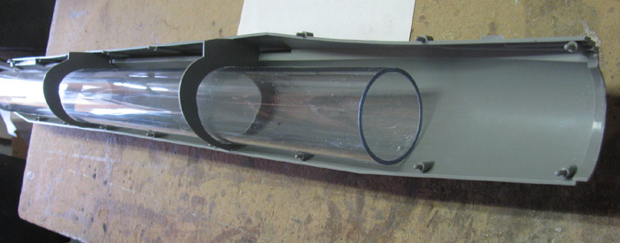
I test fit the cylinder.
I had to spread the hull about 3/16" at the front.
Other than that, it dropped right in.
December 14th =================================================
Have things to do in town but I got in to the shop for 30 minutes.
What I did was make the edge for the deck frame to sit on and not fall
in to the hull.
Measured the lower hull l opening and found the 2.5" width.
Marked the hull.
Cut some 3/8" wide plastic strips out of my 1/16" sheet.
In the photo the strips are in at the front and back.
They go front 1/8" to nothing where the 2.5" ends.
The center section is still clamped.
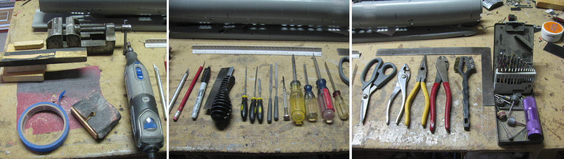
After doing this, I thought I would lay out the tools I use the most.
This will go with the post yesterday.
December 15th =================================================
Sanded the deck middle to stern section joint.
The joint on the sides where glazed yesterday.
Looks like a little more glazing to fill a low spot.
Assembled the deck and deck frame.
Set it in the hull to check for fit.
Looks good.
Test fit the bow section deck piece.
Tom mentions that the deck had a slight rise at the bow.
Looked for it and there it was.
Measured the rise.
Glued a piece of sheet plastic to the under side of the deck piece.
Let it cure.
Found some wooden blocks and small scrap pieces of plastic to level
the deck and make the needed rise for the bow.
Placed the deck upside down on the blocks and shims.
Cement on the extra plastic piece then the edges of the bow piece.
Put on the main deck and moved it to line everything up.
Put pressure on the seam and then steel blocks to hold it all down
to the shim blocks.
10 minutes later I turned the deck over.
Test fit the deck to the deck frame.
Sat it all on the hull and found that when I put the 2 deck sides at
the bow on, I need to make sure I have the deck all the way back to the
hatch stop at the stern or the sides will not fit the alignment pins.
Took it all apart.
Glazed the low spots on the stern seam.
Brought the Flat Black paint in to the house to warm it.
On to washing the deck frame which will get Flat Black on the hull
shaped areas.
The painting has started.
Made a mistake.
I should have put tape on top of the flat areas where the deck will
be bonded to the frame.
Now I will have to clean the paint off. oops!
The day is not over and I have done a little more.
I put a few more parts on the conning tower.
Built the kit stand because the hull keeps rolling on me while I try
working on it.
Cleaned the paint off the deck frame where I need to apply cement.
And yes, I mounted the deck to the deck frame.
The deck side is not cemented. I used it to get the frame and deck in
the correct spot.
This will make the side panel tight to the deck.
Before I bonded the deck to the frame, I again put wooden blocks and
plastic shims to get the correct curve in the deck. (or close to it)
The deck is not flat.
December 16th =================================================
Later start this morning.
First thing I did was do some sanding on glazing on the bow.
Just things I didn't see earlier.
Test fit and found the hull was to narrow at the bow hull joint.
Make a plastic spreader bar.
A length of plastic longer than the gap across the hull.
Then added another strip of plastic that was a little shorted.
This allowed me to set the bar across the hull and the long piece set
on the hull and the shorter piece would push the hull sides out as I move
the bar forward.
You can see it about 1/2" back from the bow section on top of the hull.
Applied the cement.
Put the bow on and centered the bottom center line.
Moved the spreader bar forward and twisted slightly on the bow to get
the bow to self center.
Before I put the bow on, I made sure everything that needed to be in
the bow was there.
Don't want to have to work down in such a small space.
Moved on to the stern.
After yesterday's mess while making vent holes, I glazes some of the
holes that didn't look like they were right.
I hand drilled a few hole again.
Glazed the slow spots I could see.
Set the parts aside to cure.
Not quite ready to instal stern section to hull.
Note: I put the small holes between the torpedo tubes on both the stern
and bow.
I did not have a drill the right size.
I did have some piano wire that was close. (.028")
Cut a 3/4" piece and put in the Dremel.
I left the end of the wire with the cut edge.
I drilled 2 holes at a time and removed the melted plastic from the
wire.
I have used wire to make holes on wood and plastic.
I have even used a sewing needle to make holes needed.
Installed the front side deck panels.
Bonded to the deck and not the bow section.
Will remove with the deck.
December 17th =================================================
Checked fit.
Glazed the deck side panel joint.
Back to working on the stern section.
Cleaned up the glazing where I had drilled holes.
Some had to be filled in and today I redrilled them.
Not perfect but much better.
Checked fit and installed the rudder and planes.
Cemented the 2 stern section halves together.
The propeller aft bearing strut was install.
It was cut in to 2 pieces to give access to the rudder.
Made a piece from plastic to put in the slot in the rudder capture piece.
I want to drill a hole doe a retaining screw.
This will give access to remove the rudder control rod and rudder.
Access to the Allen screw holding the rudder control arm is through
the top right torpedo tube door which was cut out.
I cut more plastic out of the top of the stern section that will be
under the deck.
I think I will be joining the hull with the stern today.
Going to give the stern cement time to cure before putting pressure
on it to spread the hull to fit the stern section.
==========================
I have made up my mind on what I will do with the stern.
I cut it at the front edge of the rudder. (it is cut in the photo)
Continuing the cut I made on the skag.
The cut piece lifted off.
Rudder and control rods set in place.
Make a new rudder shaft and control horn.
Measure the shaft before cutting so I can get the length correct when
I make the new one.
How I drill the shaft and keep it straight?
I cut some short pieces of brass tubing
One goes over the old shaft piece.
One goes inside the first piece which should be the diameter of the
old shaft.
The inside diameter is the brass tubing I will use as the new shaft.
Drill is size of new shaft to be used.
Slip the large brass tube over the plastic shaft.
Slip the next smaller brass tube in to the larger one.
The shaft size drill should fit in to the brass tubes.
Ready to go to the tool shed and use the drill press to drill the holes.
Go slow and pull the drill out often to get rid of the plastic on the
bit.
And remember there is about 1/4" of plastic before I get to the plane
itself.
Then I want about 1/2" into the planes.
(I did this for the rudder as well)
Test fitting the new shaft in to the planes.
I made a new shaft assembly and horn which is all soldered together.
{I need to straighten the control rod.)
The brass tubes in this photo are not the same tube I used to drill
the holes.
The larger of the 2 tubes was 1/8" to fit the planes bracket on the
skag.
It was cut to the width the 2 planes where to be a part..
The second brass tube fits in side the 1/8" and is 1.25" long so there
is a minimum of 5/8" in each plane.
Control rod resoldered to make it straight.
Glue was put on the ends of the small tube and the tubes where pushed
in to the planes until they stopped.
Before I disassembled the old assembly, I marked the ends of each plane
to get the angle correct when rebuilding.
December 18th =================================================
I have attached the stern part that was cut out.
Using a long stainless screw from a bad micro servo, I drilled a hole
through the front torpedo vent hole.
You can see the head of the screw if you look closely.
It threads in t a plastic block I put on the bulkhead center plastic
that sticks past the opening in the hull.
Time to start installing the small detail parts.
Bilge keels.
Removed the cut section, I looked at the 2 cut edges.
The edge on the cut piece is straight.
The edge on the hull side is a bit uneven.
Just enough to see the seam cut after the screw is snagged up.
I glazed the edge on the hull and will sand it smooth after it cures.
I sanded the deck sides I glazed yesterday.
Found one small place to glaze again.
What to do?
I washed the rudder and planes preparing them for paint.
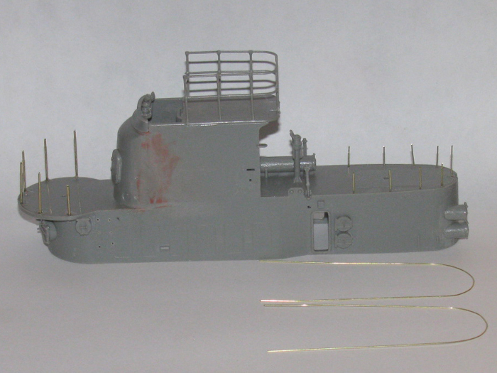
Might as well start putting the detail parts on the deck.
Some of the parts are very fragile.
Where I can, I will attempt to make the parts out of brass.
Here the sonar has been duplicated.
I [places a reinforcement plastic block under the deck to help support
the sonar mast.
2 parts.
1/16" brass rod for mast and 3/32" brass tubing flattened leaving in
an oval shape.
Drilled a hole through one side at the center for the rod to go through
but not all the way.
Soldered. DONE.
December 19th =================================================
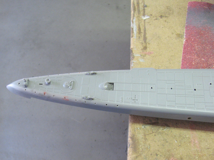
Started this morning by Installing the sonar "T".
Made the pole that sits at the bow.
Sanding to fit the stern cut piece to the stern section.
I have a fit I like so it is time to join the stern section to the
main hull.
Find my spreader bar and get the cement.
Why two bottles of cement?
The round bottle is empty. (almost)
The square bottle is half full and the one I am suing.
The square bottle has a bush for pin point spot bonding.
The round bottle has a wide full brush for paint on cement.
I use the big brush.
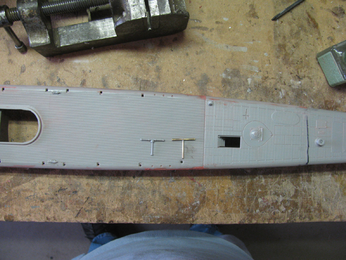
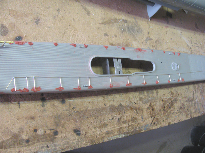
Filled the square holes in the deck where the lifeline stanchions go.
I thought I would try making a brass railing.
THis what I have so far.
Problem is, when I try to solder the low line on the stanchions, the
top rail comes off.
This may not be used.
However, I was reading the instructions to find the stanchions on the
parts trees and it says to use the supplied thread.
Thread?
Here is what I am thinking.
After finish sanding the deck to get the deck flat where I glazed the
stanchion holes, I could drill holes for the brass stanchion posts.
CA them in place from the under side.
The I could use the thread and CA it in place on top the stanchions
The the lower line.
Once I get the thread on, I will run a test.
Put 2 stanchions on a block of wood.
Put the thread between them.
Make sure the thread hangs correctly to represent cable.
Paint the stanchions and thread with the black the deck will get.
If that works then move on to the deck.
If not try again and CA the thread full length.
December 20th =================================================
Sanded the stanchion holes.
Sanded a few other spots.
Glazed those spots needing more.
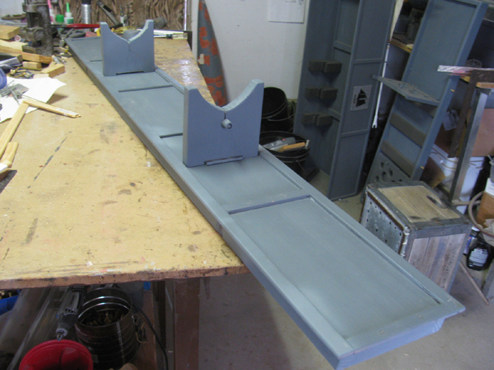
Set the hull on it's stand and place the deck and conning tower in place
to get measurements to build the transportation box.
It works out that I can build a short box by taking the conning tower
off and placing it next to the hull at the front or back.
The conning tower is taller than the hull with the sonar on the bow
and pole at the stern.
Couple of days ago, I painted the stern planes and rudder.
December 22nd =================================================
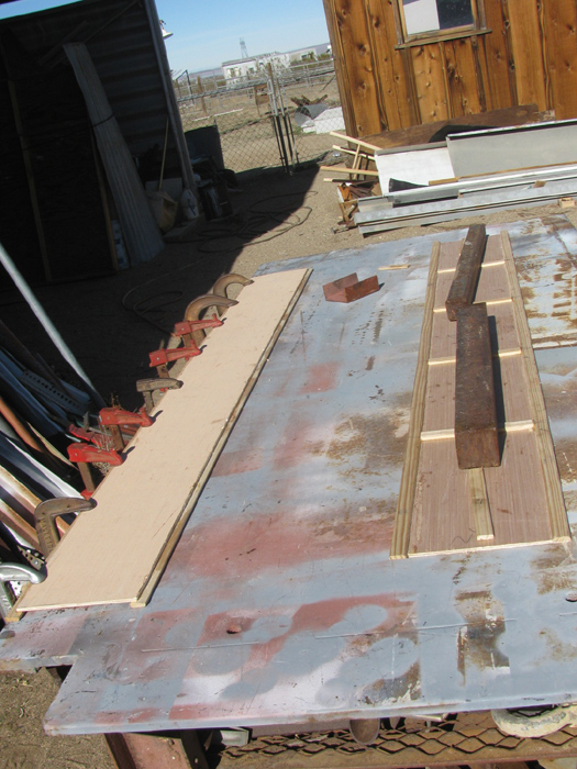
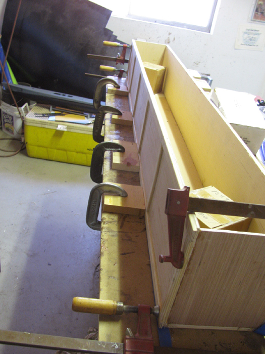
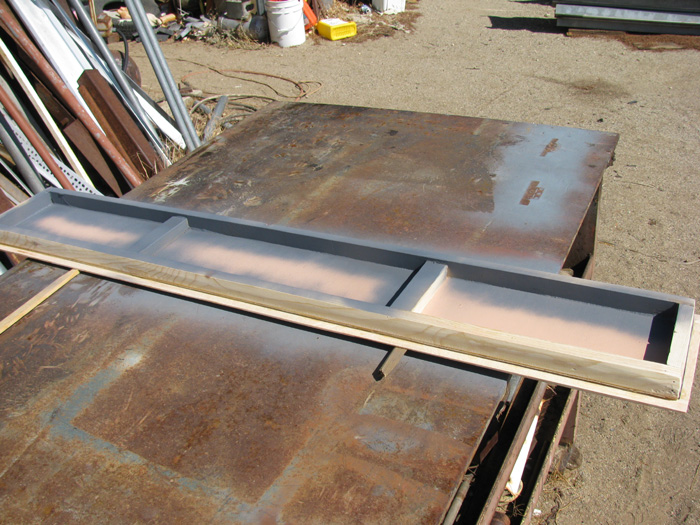
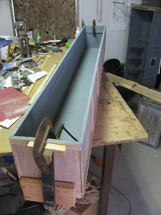
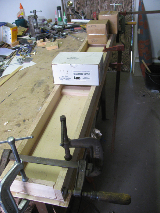
The building of the transportation box has started.
December 23rd =================================================
I got 1 hour in the shop.
I unclasped the box panel and trimmed the glue off.
I was still inside the window where the glue would cut easily.
In stops it was getting hard.
After trimming, I have a tool made from an old file I use to scrape
the excess glue off with.
It's like a 1/4" wide chisel.
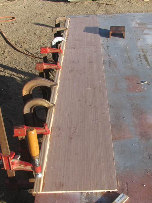
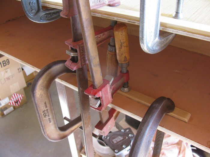
After trimming it was time to put another wood trim strip on.
Used less glue this time hoping there is less to cut off later.
It wasn't that much but might well see if I can find the correct bead.
Got it glued and clamped on the bench again..
I use the outside bench because it is 1/2" thick steel and it is straight.
Any paint of glue that gets on it comes off with a 4" grinder.
Now in to the shop.
Looked at my 2 test pieces of plastic and epoxy.
Well, they are holding together so I guess I will do the hull.
Got the fiberglass strips in.
Not fun working this messy down in such a small opening.
I did find a box of latex gloss in a draw in the house.
I even used them.
Glad I did.
Got the fiberglass strips down on the seam.
I cut strips so I could skip the flood holes the best I could. There
will be some filing but only 2 or 3 partially covered.
For my first experience with epoxy, I think I did okay.
Got the strips in and then I grabbed a clean rag and wiped the spots
I got epoxy on the outside of the hull.
Got a few finger prints at the bow and stern joints.
I am amazed how clean this came off.
I got epoxy on the 2 nylon servo connectors.
I have lots of spares (just got a package of 10) and I can replace
them but I think once the epoxy cures, it may just pop off.
Will see.
More tomorrow. Another strip on the transportation box.
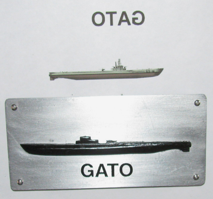
Printed out the needed 3 images of a GATO to make the badge that goes
on the Transmitter case.
Glued them to the plastic pieces with the plastic cement.
They are there so when I get some time in the shop between projects,
I can carve on them to make the 3D.
Put the letters on the transportation box badge.
Clear coated it.
It is now ready to install on the box when I get it done.
The reversed GATO is the template to put the vinyl letters on.
The small images is the size of the image going on the transmitter
case.
(I have cut the 2 pieces from plastic and shaped the back one.
The front one is rough shaped and is on the first in the vise after
applying cement.
The image at the bottom is the transportation box emblem.
December 24th =================================================
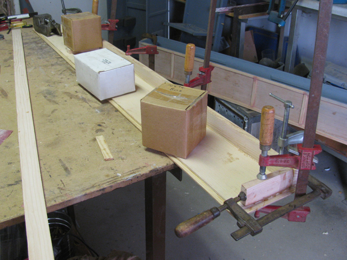
Unclasped one panel and started another.
I did this about 20 minutes ago and I can see the glue foaming out
from under the strip.
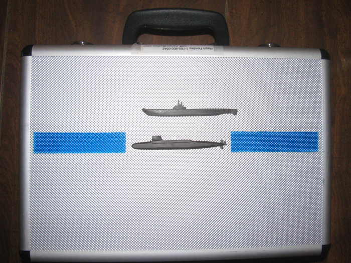
Went in to the shop and spent 15 minutes shaping the Tx case badge.
I think this will do nicely.
It is just sitting there for now.
I will paint the blue stripe in the next day or 2.
Then I can mount the badge with silicone.
Note" the badges are not to scale.
All badges are 4" long on the cases and 6" long on the transportation
boxes.
December 26th =================================================
The Gato build did not get set aside.
Early this morning I went out and trimmed a box panel.
Move back outside to the metal work bench and glued up another trim
strip.
========================
Came inside and started the ugly job.
Work on kitchen.
Cut the floor out to get to pipes.
Then cut hole to joist for support frame.
Went to town and got parts.
Next I need to lay on the floor and see about cutting out the rest
of the old pipe and installing the new sections of pipe.
1 Tee, 3 straight connectors and about 18" of plastic pipe. 2 pieces
total.
But there is submariner building going on as well.
Prepped and painted the bow.
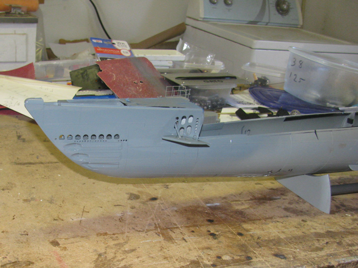
Later I painted the hull.
The stern piece is there somewhere.
It got painted before the hull.
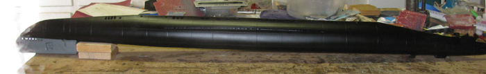
I see I have to clean up the bottom of the bow planes. (gray)
And I will need to paint the top of the bow planes black.
Just a little paint and it looks like I am getting some where.
===============
Back to the pipes.
December 27th =================================================
I have unclasped and trimmed panel 3.
Got panel 4 on the bench and it is glued and clamped.
Looked over hull paint.
Needs a second coat. We all knew that.
--------------
9:45am I have water restored.
Got the hot water tank lit.
Soon a shower and off to a meeting with insurance. (pay the bill mostly)
========
When I get home this afternoon, I may get that second coat on the hull.
Will look over the deck and see if I can do the black on it.
=======
Got home to cold, wind and the annoying dust.
Painting will not happen today.
-----------
Good news is I see no leaks at this time.
Got the lumber and things to start replacing the floor I cut out.
December 28th =================================================
Went outside, not happy about that (38 degrees), and unclasped the box
panel.
Cut the excess glue off.
Went in to the shop to get out of the wind and cleared a place on the
work bench to do another panel.
This one is different in that the trim board needs to hang off the
edge so it will be flush with the side panels when assembled.
This is the top.
Cut all the short trim boards that go across the panels long side to
long side.
I will start gluing those in place tomorrow.
Still in the shop, I lightly sanded the black part of the hull with
really used 180 wet/dry sand paper.
Later today, I may turn on the heater in the shop to get it warm enough
to get the second coat of flat black on.
While sanding I was looking at the deck.
Not sure how I want to paint it yet.
All black upper deck.
Upper deck with that wavy line at the edge.
Just the deck boards leaving the rest gray.
Before I get criticism, remember, I am not interested in being detail
correct.
If I was, my boat would look like all the others out there.
I have gotten myself in to a dangerous position.
I am thinking about trying to do a little weathering. (I hate painting)
Maybe a little wear on the deck walk paths.
If that goes okay, maybe a little rusting.
Maybe, I will just move on to the wtc.
December 29th =================================================
Back from town where I got the nails, screws and hardware to finish
the kitchen floor.
============
It has warmed up a little.
Out to the box panel.
Unclasp and trim the glue off.
Apply glue to the last long wooden trim piece on and clamp.
I also fit some of the cross trim pieces and applied glue.
The steel bars are holding the trim boards down.
Bars are 2.5" square solid bars.
I use to make trailer hitches for pickup trucks.
While I was out working on the transportation box panels, I had turned
on the heater in the shop.
It took maybe 15 minutes to do the wood stuff, it was a little warmer
inside.
I sanded and scribes a few lines on the deck where I had glazes.
Painted the sides of the deck and a few places on top the deck I wanted
gray.
December 30th =================================================
Took the deck outside and placed it on the hull with the conning tower.
(wondering if the gray is too dark?)
Removed the clamps from the panel that was on the bench.
Removed the steel bars as well.
Put the 2 ends trim boards on the the panel.
Setup to do the short trim boards on 3 panels.
Found a few items to use as weight to hold the trim boards down.
Yep, those are small steel targets at about 4 to 7 pounds each.
They will do nicely.
I move each trim board around to get the glue to squeeze all over the
board and get some of the excess out.
If I were to put the weight on without doing this, the boards will
slide off their marks.
I have the bottom panel ready fro trim boards but not enough weights.
December 31st =================================================
Late start this morning.
Spent 30 minutes outside at the metal work bench.
Trimmed the glue from all the short cross boards on 4 panels.
Got the belt sander out and sanded the edges to get the panel and the
trim boards straight and flat.
Got the palm sander out and sanded all the trim board joints to get
the glue flat down to the wood.
Besides being cold (30F) the sky is turning dark and rain clouds are
coming.
I do not want to do any gluing if it rains.
Moved all the panels in under the tool shed roof.
I am going to stop for now but later if it warms up a little, I may
go out to the shop and sand the gray paint on the deck to get it ready
for a second coat.
But that may wait.
I have looked a more photos and I see where I would like to put a few
small holes so the air under the deck and get out.
These will all be foreword in the front 6" of the deck.
January 1st - 2019 =================================================
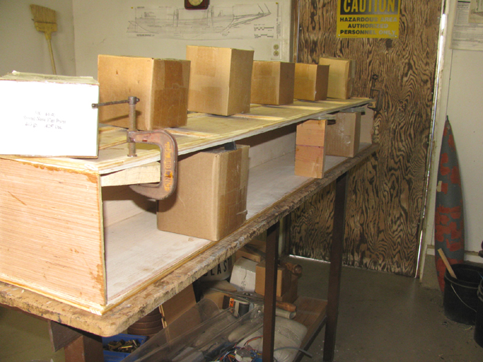
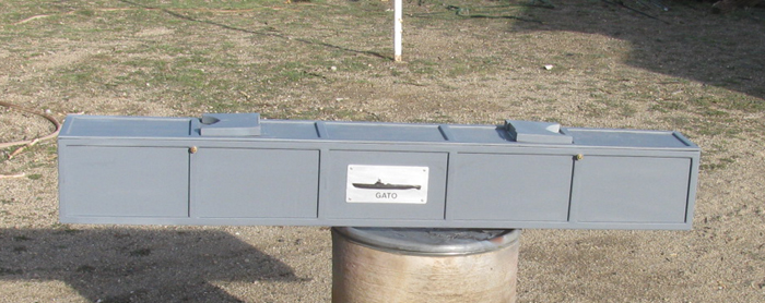
Assembly of the transportation box.
Sanded the bottom panel to make sure it was flat and straight.
Test fit the 5 panels.
Bottom, 2 sides and 2 ends.
Apply glue, clamps and several heavy boxes.
Clamps on table edge and boxes on back side to hold box panels.
Example:
There are 9 or so boxes holding the panels.
2 are clearly seen inside the box to keep the bend out of the bottom
panel.
Each box weights between 22# and 27#.
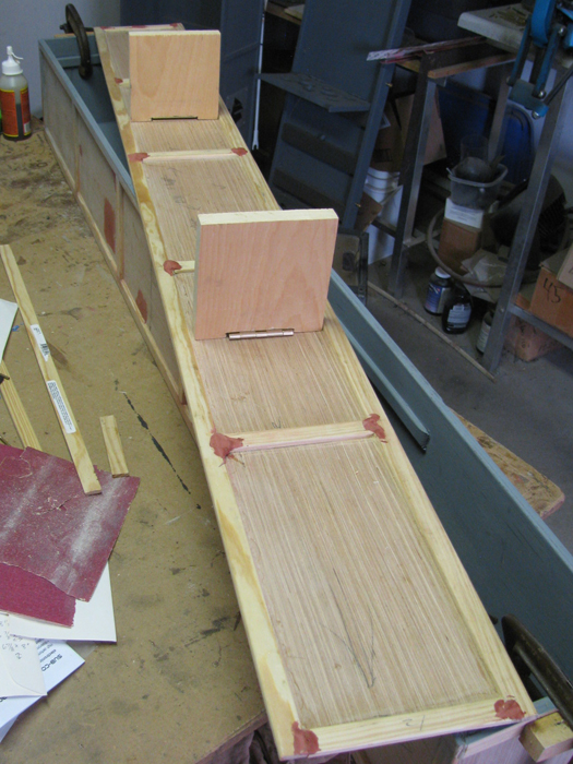
December 7th =================================================
The box in the photo above had the glue fail due to freezing over night.
The glue broke apart with very little effort.
Took the box apart and sanded down all the glued edges preparing it
to be reassembled.
Below shows the last panel being regaled in place.
Small boxes inside the box are to hold the open edge level and straight
at the correct distance from the other side.
The small boxes on top are to hold the panel down while curing.
The small 4"x4" boxes weight about 22 pounds.
The 4"x5" boxes weight in at about 26 pounds.
On the ends are small clamps with wooden block to hold the end panel
to it's correct position.
When I place the end panels, I lean them in about 1/8" so I have pressure
on the clamped block when I get to this point in construction.
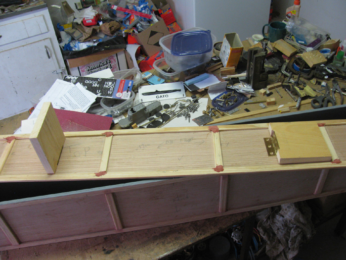
To finish the box, I will and all the edged then add the remaining 2
trim boards on each end.
Then comes fitting the top panel.
Besides finishing the box, the box will come off the work bench tomorrow
and the boat will go back on the bench.
Went out to the shop to check on the transportation box.
All looks good.
Saw the conning tower sitting on the bench.
Maybe a little time on it making railings.
Got the rear and front deck stanchions cut and installed.
The rear railing has been cut to right.
The front railing is still over length.
Before working on the horizontal rails, I will straighten the stanchions
up.
And I need to bend the front deck stanchions to have a slight curve
outward.
The rear deck horizontal railings are sitting in front of the tower
with the needed bend put in.
December 8th =================================================
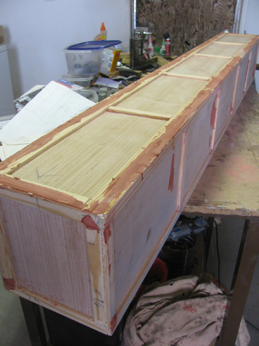
To main part of the transportation box is all glued together.
The lid has been fitted and all trim boards are currently glued in
place.
Clamped and weighted.
I have cut the boards that go inside the box to support the lid frame.
(Skipjack box build)
I do not have the lumber for the frame.
Going this morning for lumber and hardware.
Hinges and brass bolts, blind nuts and thumb nuts.
Here is the lid for the Skipjack box showing the frame.
Brass bolts to hold the lid on and a hinge for the hull stand. (also
Skipjack)
Took the main box out to the metal work bench because the lid is still
clamped to the shop work bench.
Glazed all the trim joints and panel seams.
Tomorrow, I will belt sand all the trim boards and seams.
Well, that took all of 15 minutes.
Okay, back to the conning tower.
Make 2 balsa boards to hold the upper brass rail in place for soldering.
Make 2 balsa boards to hold the lower brass rail for soldering.
I did the upper rail first and then the lower.
Need to file a few rough solder joints.
CA glue the ends to the tower and the first plastic post.
For the front railing I need to bend all the stanchions.
I will use 2 wooden blocks and make the curve I want to bend the stanchions
to.
Put the brass rod in between the blocks and press together to bend
the rod.
December 9th =================================================
Cleaned up the box lid.
Did some glazing on the trim joints.
Moved on to building conning tower railings.
The brass work is done.
I do need to do some bending adjustments to get the clean look.
Though I have looked at a lot of photos and almost all have beat
up railings.
Only those coming out refit have smooth curve railings.
There are so many different variations to choose from.
The good thing is, I am not a stickler for any particular boat.
I find something I like on a boat and try to use it.
Then I find something on another boat and I will use that as well.
Conning tower railing has been the current project.
The 1/72 kit comes with a 2 rail upper deck arrangement.
The original lay out was for a cable railing and the kit supplied thread
to use for the railing.
The stanchions are so fragile, I decided to use brass.
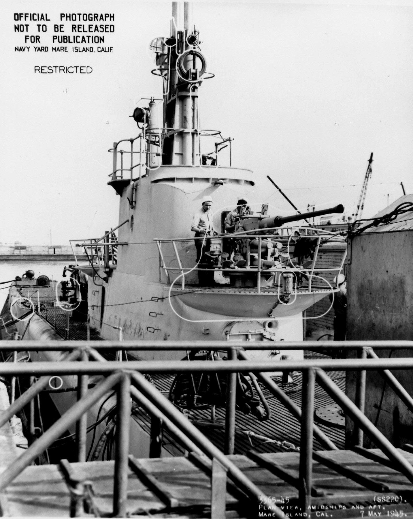
Looked at photos, a lots to pick from.
add photos here
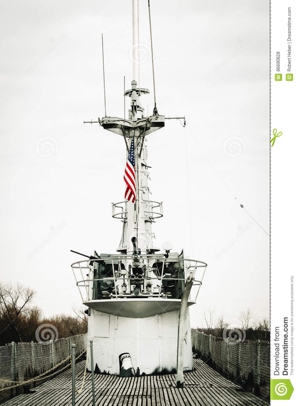
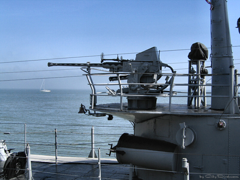
This one looks like the one in the kit except it has welded pipe rails
instead of cable.
This is the image I used when making my railing.
December 11th =================================================
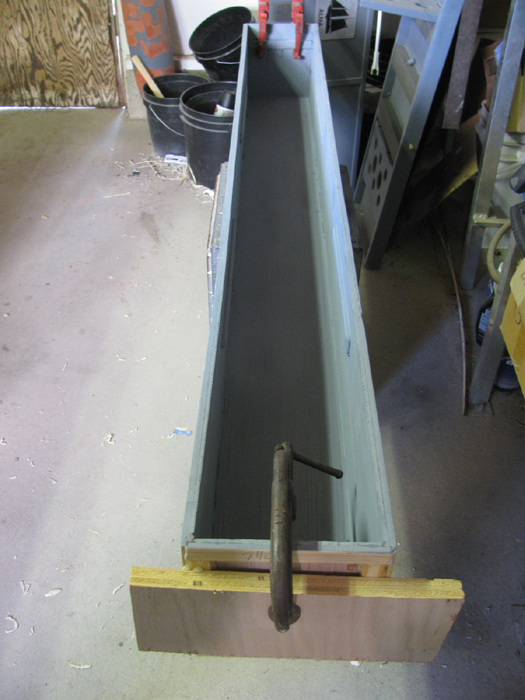
Cleaned up the inside of the transportation box.
Primed it with gray.
The clamps are holding the bottom outside trim board s that where glued
on after the painting.
Time to build the box stand pieces.
Did the measuring of the box width and the height I want the boat to
sit on the stand.
Cut the pieces.
Cut the notch in the bottom of the stands for the hinges.
Here the stands with the hinges sitting on the lid.
Another look of the stands pieces.
One up and one down.
Moved the transportation box off the bench.
Gluing the half the frame to the under side of the lid.
Also glued 1 stand screw block to the underside of lid.
Third box back is sitting on the screw block. (screw block is where
the screws for the stand hinge will be anchored)
December 12th =================================================
Today's gathering at the pond was canceled due to rain.
I was in the shop for an hour cleaning up yesterday's gluing.
I have 3 more frame boards to put on and the lid will be finished. (the
wood parts)
Cleaned up the glue on the box.
Noticed I missed 4 end trim boards.
I had been wondering why I had these short pieces sitting on the work
bench.
Got them installed and clamped.
Next I will sand the box because there are spots with glaze that need
to be smoothed out.
Then on to painting the outside.
December 13th =================================================
Removed all the clamps from the box and the lid.
Trimmed the glue and sanded.
Glazed the box, again.
Trimmed the glue from the lid.
Sanded the frame boards to round off edges.
Test fit to box.
First coat of primer.
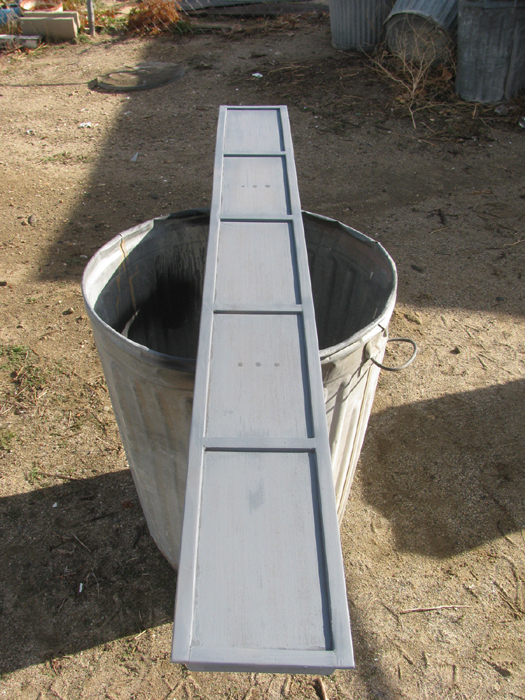
Cut the stand to the shape of the hull.
Notched the stand for the cable that will hold the stand pieces up.
First coat of primer on.
Second coat on all parts in about an hour.
December 15th =================================================
It is suppose to rain today.
This morning it was foggy and wet.
This afternoon, there was a couple of times the clouds parted and the
sun shown through.
Got a second coat of primer on the lid and the stands.
Got 2 coats on the stand saddles where I file the cut to fit the hull
better.
Here is the lid back inside on the bench to dry.
During the second sunshine moment and got a coat of primer on the box.
Still sunshine an hour later and I got the second coat of primer on
the box.
Took the box inside to the bench to dry.
It has started to sprinkle.
Weather says storm coming in is more intense than yesterday.
I got what I wanted done so, let it come.
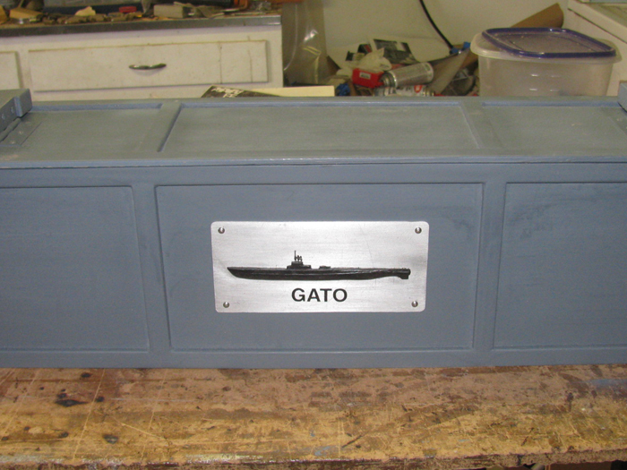
Tomorrow, I will reinstall the boat badge on the box.
December 16th =================================================
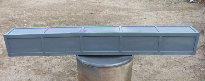
Started by installing the ID badge.
Cut all the foam that is inside the box to support the hull.
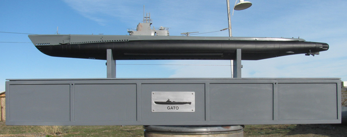
Transportation box completed.
The boat is inside.
Hull, conning tower, rear gun and rear upper gun sitting in place.
December 20th =================================================
Late start today.
Yesterday was subnormal gathering at the pond.
9 to 12 submarines showed up and a 4 Viking rowers with sails.
My Akula II ran great.
My Skipjack ran great but there is a small air leak.
Only get bubbles when fully submerged and the pressure in the cylinder
is at it's highest.
No water in the cylinder after 2 one hour runs.
I am happy.
Now I need to find where the bubbles are coming from and see if I can
stop them.
-----------------------
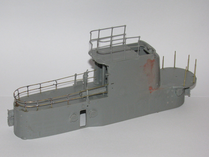
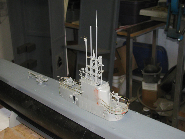
In the shop and back at detailing the conning tower.
Got the tiny wire steps installed.
Lost several.
Found all but 2. (made them out of .020" brass wire.
Built the third deck gun.
The little one.
Drilled a couple of holes to let air out from under the conning tower
deck.
These holes are under the guns.
You can see them but you have to look for them.
Detailed most of the periscope tower.
Not sure I got everything on there.
There are some parts I decided not to even bother with.
Put a couple of pieces I think are metal support frames on the tower.
I see I have to make 2 bars for the front of the tower railing.
The plastic ones did not survive removal from the tree.
I have got to find my small air and water pumps.
I will get a photo or two tomorrow.
Lots of parts assembled but not put in places to let the cement cure.
December 22nd =================================================
Today's project was to find the small pumps I have.
Looked every where.
I found the centrifugal water pumps.
Not really what I wanted.
Looked in the parts boxes in the shop.
Still can not find the air pumps.
Still looking.
I did look at the pump that was removed from the Skipjack.
Hump
With a little filing, on 2 opposing screw tabs, the pump fits in the
smaller cylinder of the Gato.
I originally was thinking of putting this in the George Washington.
But if I can not find the air pumps, this will do.
(For the GW, I happen to have another one of these pumps and replacement
motors)
Got to go in to town today.
So there's not much I can do this morning.
I did get a tack coat of gray on the tower minus the periscope stuff.
If you look closely, you can see the red glaze showing through in spots.
Will get another coat on later today.
Later in the day.
Conning tower is painted.
Tack coat and 2 full coats.
While I was painting gray, I painted the 3 deck guns.
January 23rd =================================================
Painting the conning tower decks flat black.
The gray is showing through.
But I am not sure I don't like it.
I may leave as it is.
Put a little thin paint on the top surfaces of the guns.
There is a little touch up to the sides of the tower where I got wild
with the brush.
Here the deck is taped off ready for painting flat black.
Currently in the house where it is warm to dry.
I'll get another photo in an hour or two after I pull the tape.
Time has past.
Painted
Tape and paper removed.
Deck sitting on the hull.
Need to make a tube for the air pump intake.
I used a 5/32" brass tube so I can have 1/8" ID for the air pump.
I should have done this before assembling the masts pieces.
I could have used the center mast.
As it is, I used the rear most mast.
I cut the mast out of the assembly with a Dremel saw blade and exacto
knife.
Removed the search light to use on the new mast and I removed the head
of the mast to use on the new mast.
This is what I ended up with.
The mast is a little bigger that the others but it gives me the needed
1/8" ID.
I drilled down through the deck of the tower to make a hole big enough
for the new mast.
Then I turned the tower over and drill through the bottom of the tower.
Did a little knife cutting to get the stanchion out of the tower.
Set the assembly on the conning tower for a look.
There is about 3/4" of brass tubing under the deck to attach a rubber
hose to.
January 25th =================================================
I have worked on the Skipjack air leak and it is ready to go tomorrow.
========
Did a little on the Gato.
I polished two lengths of stainless 1/8" rod for the propeller shafts.
Slipped them in to the shaft support bearings for a look and I slipped
the propellers on the shafts for a look.
February 2nd =================================================
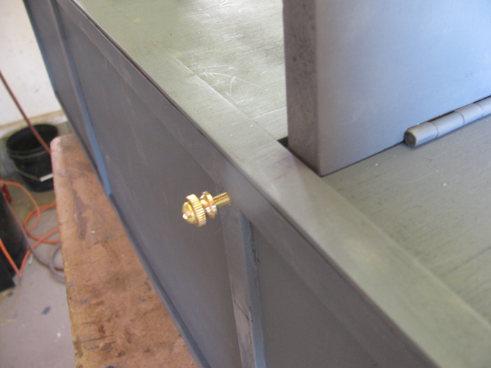
I got a small stainless bolt to hold the rear deck to the hull.
There is a frame under the deck at the rear tow eye.
This is where I am going to put the bolt. (bolt in threaded hole)
The plastic frame is thick enough, I did not use the nut.
I threaded the plastic.
Deck set on the hull and the hold down bolt in place.
I will touch up the paint later.
There are other placed to do.
The foam in the hull can be seen in this photo.
There is room for more if needed.
That will come near the end of the build.
February 3rd =================================================
Fit the rudder so it will travel full right and full left. (touch the
planes)
Had to remove some of the torpedo door plastic. (I would leave the
torpedo doors off if I do it again.. Interferes with the control horn)
Fit the plastic piece that holds the dive planes in place.
Just a little filing to get the rudder to clear the small bolt head
that holds the plastic piece on.
Made another periscope top out of brass.
The front one this time.
Touched up all the paint.
Where I filed material off and some small scratched caused by fitting
the deck to the hull.
5 minutes at most.
Will clear coat it when it warms up.
I may try some very light weathering or more like deck path wear.
With all this fresh paint, it does look strange even for a boat coming
out of overhaul.
There should be deck wear from yard worked moving about the boat in
the yards.
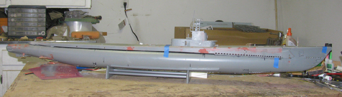
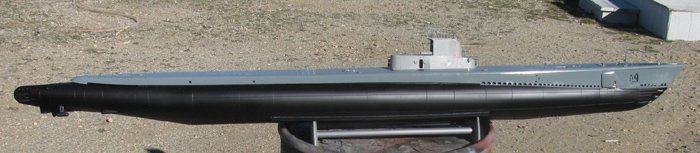
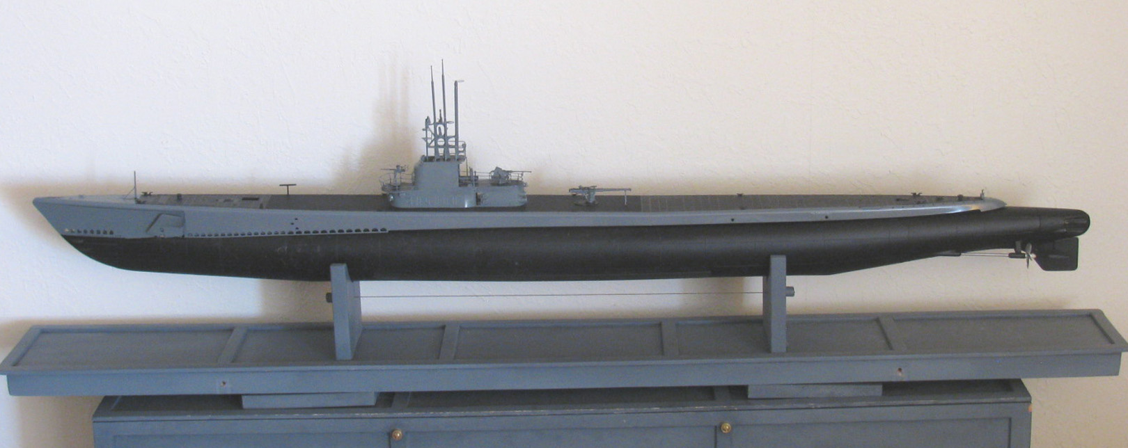
Here is the boat sitting on it's stand
February 4th =================================================
Was opening up the Skipjack to find the problem(s).
After isolating the ballast tank motor, I found it no longer works.
New motor and controller ordered.
The controller may not be bad but if it is, I have one coming.. Could
end up being a spare)
February 5th =================================================
Today will be a very short day in the shop.
I am not going to try working at 38 F for a high.
But I will get my 10 minutes plus on the Gato.
I have cut the plastic pieces to build the 1 to 2 gear assembly that
will go on the rear end cap.
The 2 main frame pieces are made of 2 pieces of sheet plastic bonded
together. (4 pieces altogether)
The re are 2 spaces made from 7 pieces of sheet plastic to get a thickness
so the gears can fit between without binding.
The frames are made.
1 end spacer has cement applied, stacked and placed on 1 of the frames.
The assembly is currently in the vise to apply pressure during the
cement curing.
Later today, I will do the same to the other frame and spacer.
This I can do on my kitchen table.
I will shape the 2 frame pieces to fit together with the 3 gears between
the spacers.
I will cut bushing stock to the gear shafts.
6 all total.
Drilling the assembly after all the glue cures.
I will get a photo of all the parts when I take the first frame with
spacer out of the vise and before I do the second one.
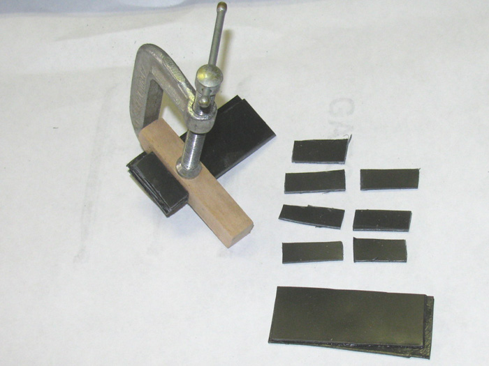
February 6th =================================================
Assembling of the gear box.
3 holes where drilled in to the frame with the standoffs installed.
Went to the drill press and started drilling bushing holes.
Using a drill bit the size of the gear center hole, I drilled first
hole and put the shaft and gear in place.
Holding the second gear with my fingers, I drilled the second hole.
Put the shaft in the hole and place the gear on it.
Turned the gears to see if I got them too far apart or too close.
I can fix that when I drill the holes larger for the bushings.
Good gear mess. (not to tight and not to loose)
Held the 3rd gear against one gear leaving a gap to the other gear.
I checked the motor rotation to make sure I get the correct rotation
for the 2 gears that will turn the propellers.
As I did this, I realized it did not matter.
If the rotation is wrong, I just have to turn the gear box over.
Holes drilled for the gear shafts.
All gears mess is good.
Now to drill the holes larger to accept the brass bushings.
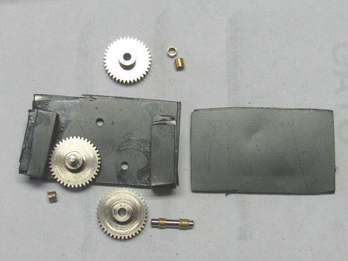
The drill was a little small but using the shaft as a guide and a longer
piece of the brass tubing, I was able to hammer lightly and drive the bushings
in to place.
Using the 2 shafts I have cut and the 1/8" drill bit as a shaft, I
placed all 3 gears on the frame.
They turn with no effort and engage almost completely.
I disassembled what you see here down to the bare frame.
Sanded the bottom edge flat on both frame pieces.
Applied cement and lined up the parts.
Placed it all in the small table vise and applied pressure.
Once the cement cures, I will use the 3 bushing holes to drill through
the second frame piece.
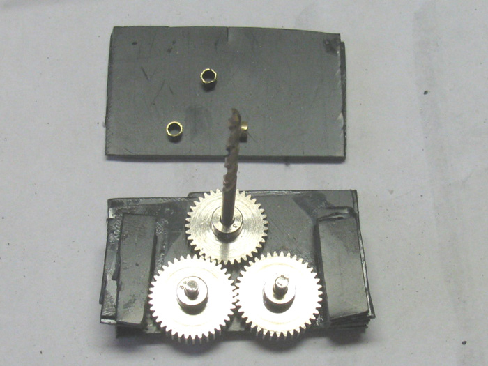
Once the frame is completed, I will shape the frame to fit the end cap
which I have not yet made.
This will also hold the main propeller shaft seal in place in the end
cap.
February 10th =================================================
Made end caps from pvc rod. (started out 4.5" id)
2.5" cylinder piece.
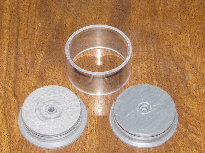
Caps in the cylinder.
I checked the o-ring groove with an 1/8" o-ring section.
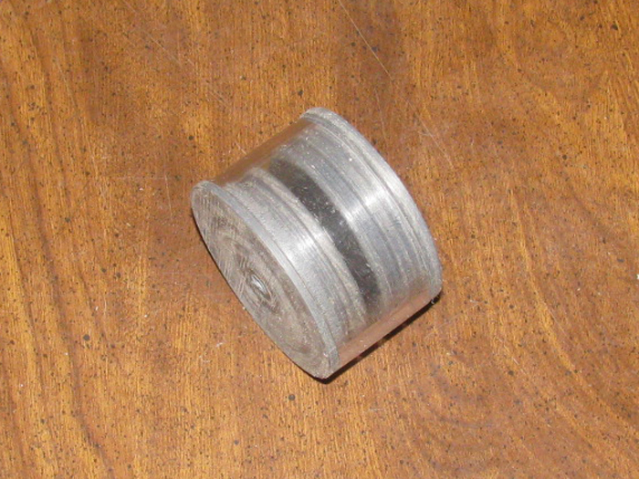
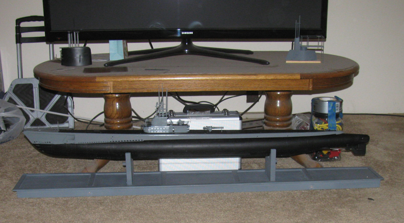
February 13th =================================================
After moving tools out to the tool shed, I did some cleaning.
Then it was time to stop and have a bite to eat.
Went to town and stopped by the post office.
Found a blue notice in the PO Box which means to go to the counter for
pick up.
Look what I got.
Boat parts!
Gears for the Gato 1 to 2 drive system and the motor and parts for the
Skipjack.
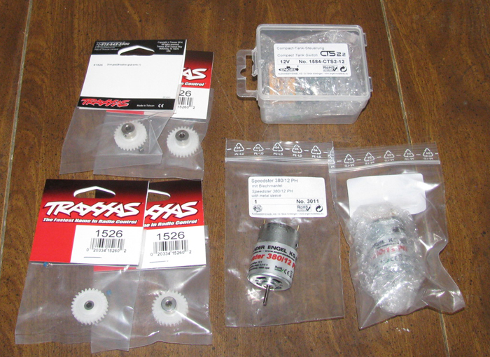
Work on the boats will continue on Friday.
February 15th =================================================
Got in to the shop for a few minutes this morning.
Cut the plastic sheet pieces to make the gear box height.
It will take 7 pieces on each side to go between the two main frames.
This will give me a gap between the frames to slide the gears in to
the box.
These pieces are now under pressure in the small vise.
Measured the gears to fine the centers and then transferred the information
on to one of the frames.
Drilled the first hole and place a shaft in the hole with a gear on
it.
Using the drill bit I pushed the drill bit through to make a mark for
the second gear.
To keep the gear teeth from being too tight, I places masking tape
strips on the teeth and pushed it down between the teeth giving me a slight
gap.
Drilled the second hole.
Tested the gears for fit.
It was very tight with the gears with the tape but a good fit when
I changed the gear with tape on it for one that did not have tape.
Placing the third gear required to have it mesh with one gear and not
engage the other.
So with the tape on one gear down in the teeth to give the clearance
needed, I put tape on the same gear but I did not push it down in to the
teeth.
This section of the gear was like a wheel.
Two layers of tape is the clearance I got when I drilled the shaft
hole.
Using drill bits as shafts, I placed all three gears on the frame and
turned the gears.
It is smooth and turns freely with no binding.
I like it.
After the cement cures on the two pieces in the vise, I will assemble
the gear box and then drill through the frame holes to drill the second
frame.
February 17th =================================================
This morning the Skipjack repairs were completed successfully.
I was surprises that only the ballast tank motor had to be replaced.
I was sure it was going to be the ballast tank controller.
It seems to work fine.
The Skipjack is assembled and the batteries charge.
The boat is back in it's protective transportation box, ready to go.
(Feb 23th is an informal gathering at the pond)
================
While the battery charging is going on, I have moved the Gato gear
box assembly back on to the work bench.
In the last hour the temperature in the shop dropped from 48F to 37F,
so I called it a day.
Only because my fingers where tightening up and I was having trouble
picking up small parts. (grub screws)
Had to use needle nose pliers.
I still have 1 transmitter battery on the charge.
Should be finished in 15 to 30 minutes.
Then I am to stay so I can get warmed up.
February 18th =================================================
In the shop a 8 am.
34 F.
Turned on heater.
Thought I would work on the gear box.
Need to start shaping the box to fit the end cap.
First thing, there is a problem.
The gears will not slide in to the box.
It appears that the pressure put on the plastic pieces to make sure
I had a good bond has decreased the internal dimension enough to be smaller
than the gear height.
Not good but not a big issue.
Out to the tool shed where the band saw is.
Using the band saw as an upright saw, I cut one side plate off.
The one I have not drilled for the shafts.
Put a straight mill bit in the drill press.
Clamped a couple of steel fences on the table and set it up to mill
the surface flat where the saw cuts are.
Two passes and it's done.
This was not fun.
There is no heater in the tools shed.
Fingers are thinking about striking on me.
Back in to the shop.
Oh! the 10 minutes out in the tool shed has allowed the shop to warm
up nicely.
Flat sand the side of the box I just cut to get the saw blade marks
off.
Put flat pieces of sheet plastic on the cuts to raise the sides of the
box.
Test by putting 2 gears in the box.
Turns out, 1 plastic piece on each side is enough to raise for gear
clearance.
Applied cement and clamped in the table vise.
I did not put the side plate on.
I want to check after it cures if it is wide enough or needs another
piece.
I also need to shape the side piece before I close up the box.
Made a new side piece.
Cutting the old one off has made too many cut lines and gouges to flat
sand smooth.
Cut 2 pieces and bonded them together.
They are now clamped between two small wooden blocks.
Okay, I am going back to the house.
The heater is doing a good job.
It's has gotten up to 38 F in the shop.
Not good enough to be working on small plastic parts on the boat hull.
Will see what I can get done later today.
After shaping the new layer of plastic sheet, it needs one more layer.
Cut the 2 pieces out and applied cement.
Back in the vise it all goes.
Still too cold to spend any time in the shop.
38F.
After bonding the parts, I brought the vise with the parts in the house
to cure.
A quick note.
Both the Skipjack and Akula II are in their transportation boxes and
the transmitter is in it's carrying case with extra batteries.
I am ready for this Saturday's unofficial gathering of subnormal at
the pond.
(next scheduled gathering is Mar 9th)
February 19th =================================================
After spending time in town with the accountant to file taxes I got
home mid day.
Out to the shop.
Removed gear box from vise.
Shaped the one layer of plastic to match the rest, I test fit the gears
in the unit.
This looks good.
Did some flat sanding on the side that will get the cover plate plastic
piece.
Still have plenty of clearance.
Applied cement to the 2 layer side plate and lined it up.
In to the vise it went.
I gathered up all the tools so I could pick out the ones that go in
my field tool box.
Do not want to be scrabbling on Friday for Saturday outing.
I will leave the tool box in the shop until Friday and use tools as
needed from the box.
========
This morning was a slow starter.
About 2 am power was out in the area I live.
This means no power to the house furnace so it got rather cold about
3:30 am.
It woke me up.
First I thought the propane tank was empty but immediately realized
no power because the lights did not come on at the switch.
Went in the kitchen and turn on a couple of burners. (old fashion house
heater. I have 1.5" thick 12" circle of steel plate just for this)
Power came back on at 5:34 am.
Furnace ran fr almost an hour to get the house heat back up to 60 F.
I decided to sleep in to 9 am then go to town after being awake most
of the early morning.
On the way to town, I saw 7 trucks working on the power poles.
Looks like someone ran one over and blew out a couple of transformers
about 1 mile apart.
Replacing power pole at one location and transformer at the other.
So far today, the high has been 39 F.
I am not going outside any more today.
Yes, I have become a wimp about the weather.
I was thinking this evening about this current project for the Gato.
The gear box.
Looking at the post, I seems like it is taking a long time to build.
I want to add some information.
If I were to add up all the time I have actually worked on the gear
box not counting cement curing, I have about 1 hour and 45 minutes in to
it.
Trying to work in the shop while it is in the 30s and the tool shed
in the low 30s, I can't stay out there very long.
10 to 15 minutes at a time.
I try to do measuring, cutting of plastic sheet, test fitting and then
cementing parts together in a time frame of 15 minutes.
If it was warmer out side, I would have this done in 1 trip to the shop.
But it is not warm.
The heater helps but takes too long to actually get the shop warm enough
to stay out there.
The heater is about 5 feet from where I work and is on my back which
feels good until I turn around and the shock of the cold hits me.
The process is to get at least 10 minutes of building done every day.
Make progress every day.
Do something.
I have been thinking I might try weather by doing a little on the decking
where people would be walking and wearing on the wood deck.
That I could do on my kitchen table in the evenings.
I thick I might bring some paints, brushes, some foam blocks and cotton
balls and try doing some weather on paper plates until I get something
I like the looks of.
Then on to the deck.
Worst that can happen is I tape the deck off and repaint the flat black
where I mess it up.
I have repainted hulls where the paint curdled.
I think I can fix a deck if I don't like it.
The boat has been sitting in front of my tv now for a couple of weeks.
I am not sure I like the look of the boat in new paint as if just built.
Doesn't look right.
Even a new boat has growth at the waterline and wear paths on the deck.
Tomorrow, I should have the gear box finished.
Then see how I want it mounted on the rear end cap so I can cut the
seals in for the main propeller shaft and the 2 control rods.
This will determine whether I use o-rings or bellow boots.
Got to find some 5/32" brass tubing.
I have some small pieces but not enough.
February 20th =================================================
I spent the morning and some of the afternoon getting read for the rain
and snow predicted for tonight and tomorrow.
Went an got a load of propane for the house.
Yes, I haul my own propane. Been doing it for almost 40 years.
Made sure the wind did not remove insulation from water pipes and faucets.
I did get in to the shop while transferring propane from the tank in
the back of one of my trucks to the house tank.
In the shop I worked on the gear box.
Took it out of the vise and scribed some lines on it to square it up
and get the correct dimensions.
Did some cutting with the Dremel diamond saw and then some sanding
to get it straight and smooth.
Cuts 3 lengths of 1/8" stainless shaft making sure I had the 2 pieces
for the propeller shafts.
I had cut 6 5/32" brass tubing pieces to use as bearings.
I need to clean them up and make them square before installing in the
gear box frame.
Almost time to start getting all the motors, pumps electronics out and
on the work bench to layout how I want every thing to be.
But I do not think I will be in the shop much for the next few days.
Highs are expected to be in the low 30's mid day.
Again there was progress today on the Gato.
February 21st =================================================
Woke up to snow on the ground and light snow happening at 6 am.
It is now 11:35 am and the snowing stopped and the snow on the ground
is almost gone.
Only left in the shadow areas.
Cold and windy outside.
Yep, I will be staying inside today because I can.
February 24th =================================================
In the shop working on the Skipjack to make some trim changes after
yesterday at the lake.
Tom, brought the correct propellers.
Originally I got two the same.
Now I have a right and left.
Cleaned them up with a file and prepared the shafts by grinding some
notches in them for the glue I use that expands in to the notches and to
the propeller hub.
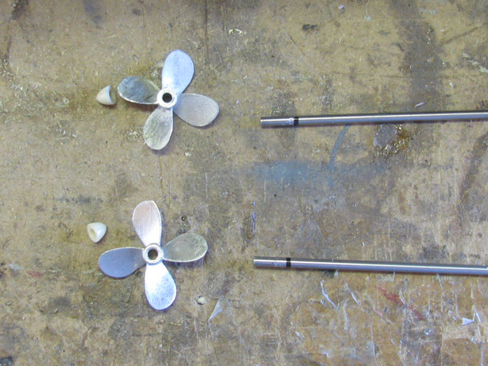
Dipped the ends of the shafts in to the glue and slide the propellers
on and then the hub cap.
Brought them in to the house to keep an eye on them and every so often,
put pressure on the end cap to keep it tight to the propeller.
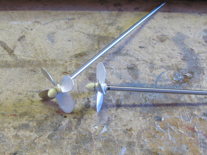
February 25th =================================================
Trimmed the glue off the shaft and hub joint.
Painted the propellers brass and painted parts of the shafts flat black
where they will show when installed.
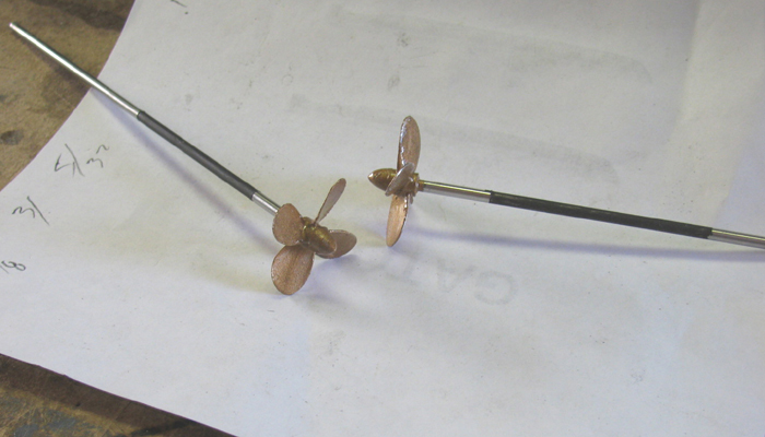
Installed propeller shafts and propellers.
Side view.
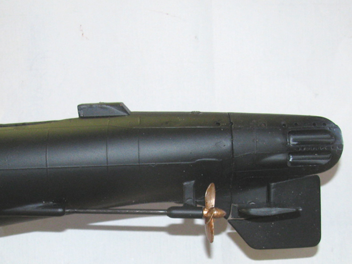
Stern view.
I see I need to do some painting in the tubes and vent holes.
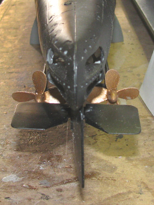
Dog Bone connector installed on the propeller shafts.
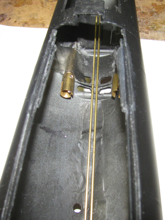
March 5th =================================================
The gear box is complete.
Here the gear box is upside down.
We are looking forward at the bottom.
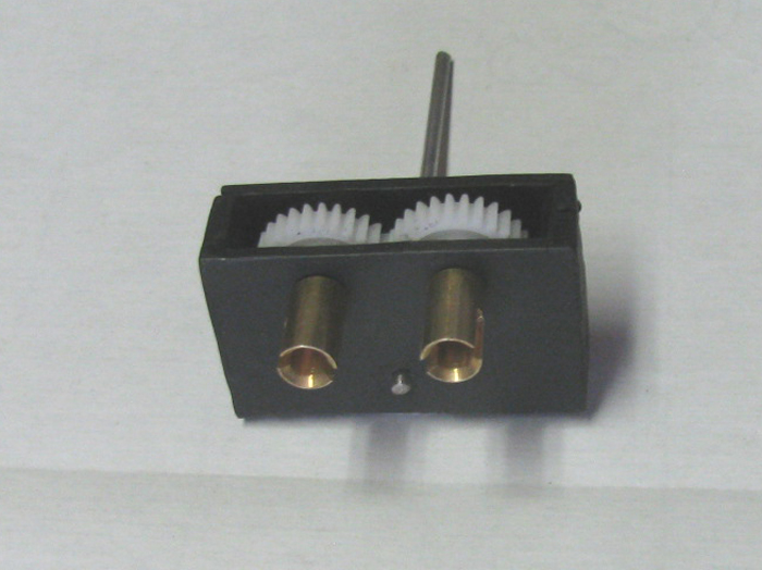
Side View.
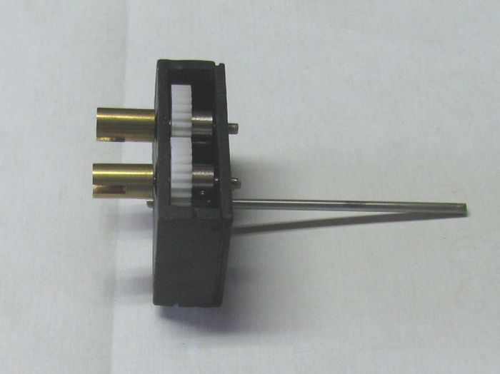
Gear box on it's side looking at the top.
To the right is the single shaft going to the propeller motor.
To the left are the two output shafts going to the propellers.
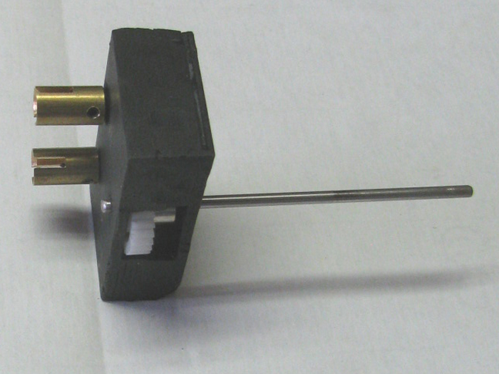
March 7th =================================================
This morning I finished the bow deck repairs where I drilled 5 additional
vent holes on each side of the bow.
I have a 1/4" hole down in the eye lead on the bow.
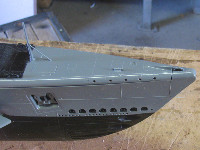
I also wanted to see how the gear box fit in the stern with the cylinder
and end cap set in plane.
It appears I do not need to do any more shaping.
The gear box fits with clearance from the hull sides.
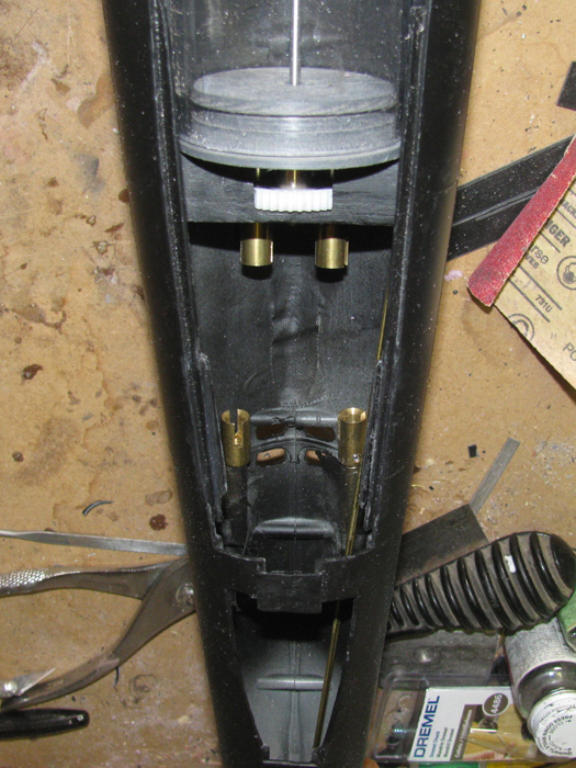
March 29th =================================================
Gathered up parts that go in the cylinder.
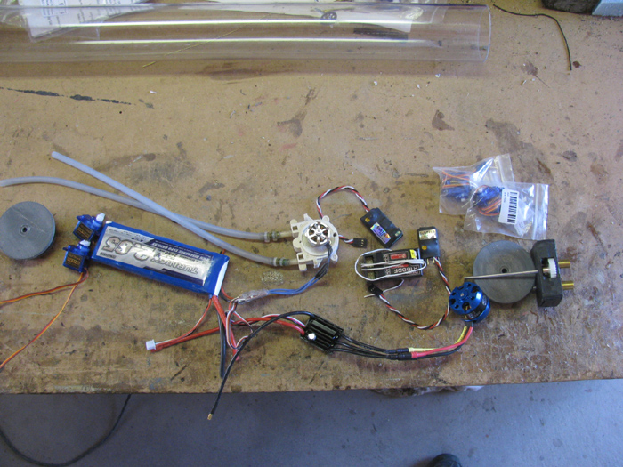
Moved them in to 2 groups.
The stern section and the bow section parts.
There may be another servo but I have not decide where it will go yet.
Have to make a test port type assembly to see if it will even work.
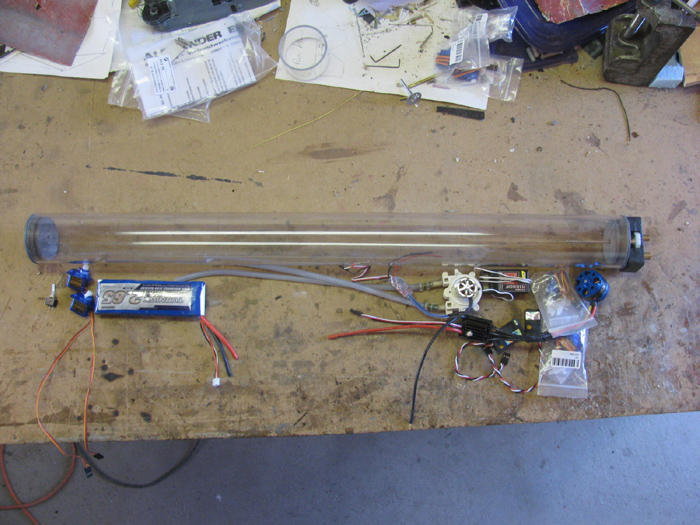
March 30th =================================================
Time to do something.
I cut some aluminum out of my STOP sign aluminum supply.
2.5"x 3"x 1/16".
Marked for the servo opening.
Drilled a hole for the power switch.
Cut the ends so I could bend one end out for mounting screws and one
end in for strength.
The long sides have 3/16" of material bent over to strengthen the plate.
Later I cut the 2 ears on the left end off.
They were not needed to make the frame ridged.
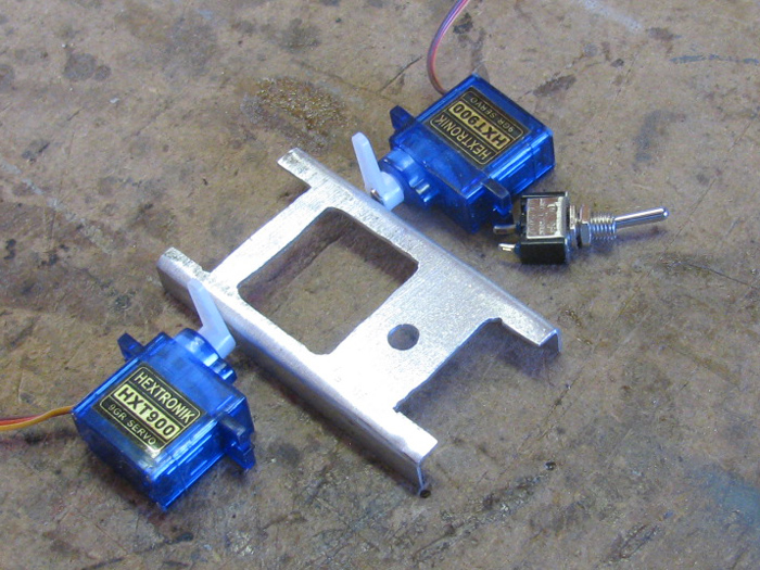
The servos will be mounted with the control horns down.
This gives me the most room for the longest horns in the 2.25" cylinder.
The aluminum frame will be attached to the inside of the front end
cap.
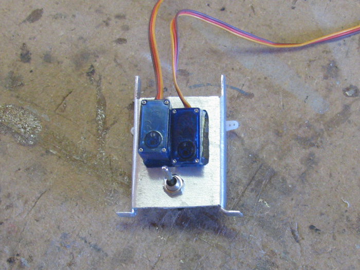
The under side.
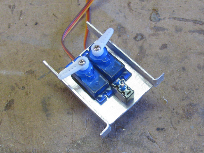
Frame, servos and switch sitting in the cylinder end piece and cap.
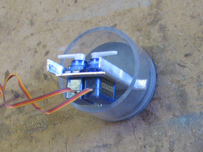
March 31st =================================================
The bow planes and retract servos have been mounted to the frame.
The power switch is installed.
The frame has been installed on the end cap.
The servos have been connected to the Rx and adjusted for center and
through.
Looking at the end cap from above.
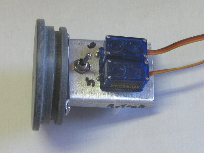
Looking at the end cap from the below.
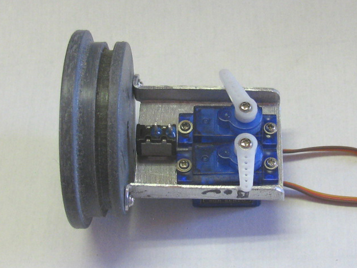
I have marked the end cap for the holes that the control rods will go
through.
I need to get some brass tubing before I drill these holes.
The tubing used as bushings for the 1/8" control rod sections.
End cap placed in the cylinder and the cylinder in the hull to check
location and clearance.
Also checked the rear of the cylinder for the gear box and dog bone
connectors.
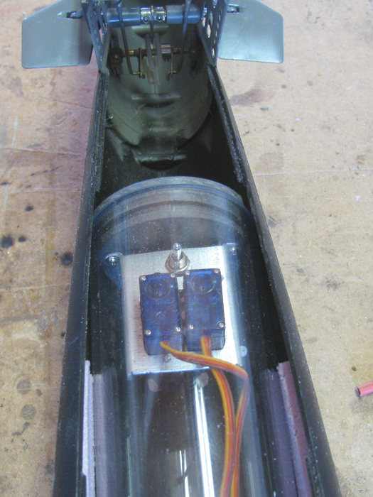
May 3th =================================================
Finally back to work on the GATO.
Fabricating the rear electronics tray.
Got my speed limit sign out and cut a 2" x 15" x 1/16" aluminum plate.
Debarred it and sanded the sign reflective coating off.
Out to the vise.
I need to make the plate 2 1/8" wide after bending the long edges over
to 90 degrees.
It does not fit in to the cylinder.
Now I will bend the edges over to about 110 degrees with my 24 ounce
ball peen hammer.
This is slow going but it is producing the results I want.
I bent 3" of one end of the plate to test fit in the cylinder.
This might do.
So I continued on bending both edges over.
It fits but is very tight.
Got the belt sander mounted in the vise and sanded the edges to clean
up the hammer marks and make the edge straight it's full length.
A little more hammering and a little more sanding and I got what I
want.
It fits without binding or dragging in the cylinder.
Looking at the bottom side of the tray plate.
Here it still needs a little more hammer and sanding work.
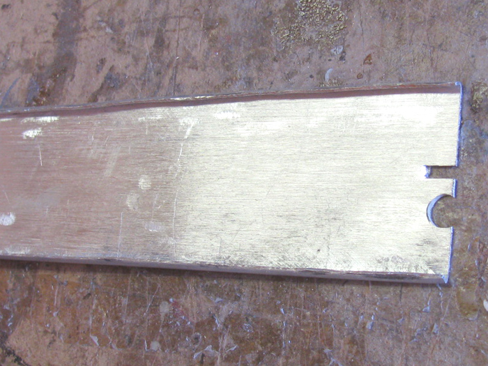
May 5th =================================================
After getting the tray cleaned up, I measured for the motor and 2 servos.
Hole on the right is for the main motor and the hole on the left is
for the 2 servos.
It is hard to see but I bend the right end of the motor hole to make
a mounting bracket for the motor.
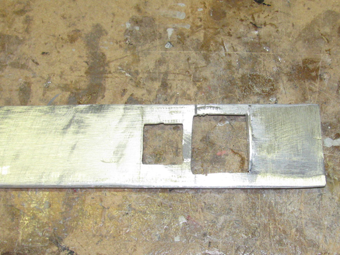
Here I set the servos and main motor in place to check fit.
The right end of the tray still needs a notch cut and two tabs bent
down to mount to the end cap.
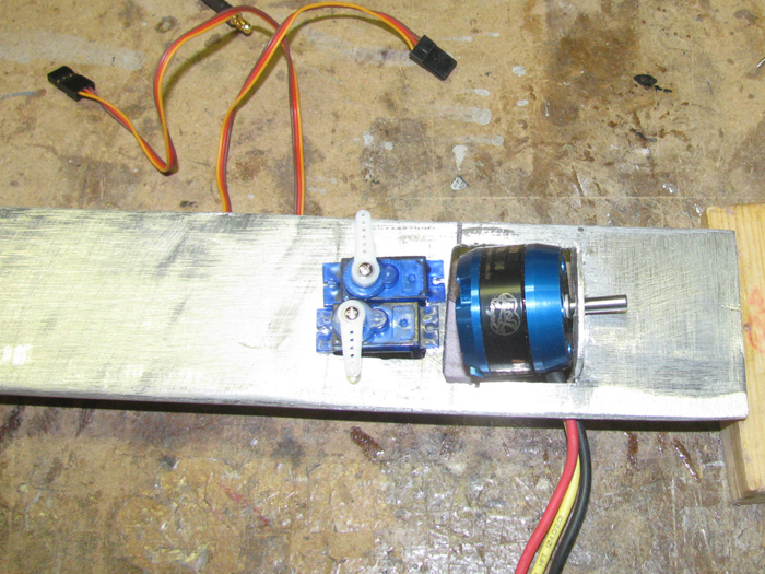
Here are the other parts that need to be mounted.
The ESC and Fail Safe (on the table) will be mounted on the bottom
side of the plate.
Not shown are the ballast pump and ESC for it which will go on the left
end.
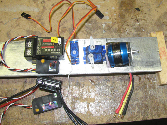
June 17th =================================================
Repairing broken periscope mast.
2 masts sections, 4 tubes to down size to periscope rods, 2 periscopes
and 2 bottom pins.
Painted
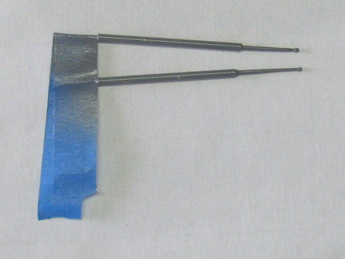
Tape removed
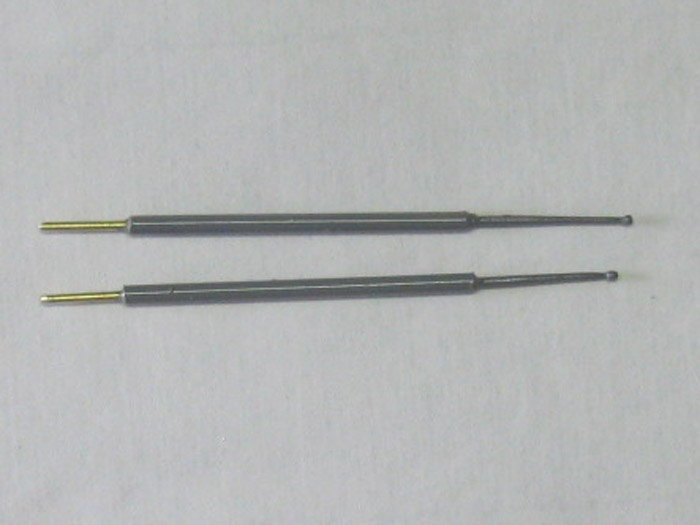
Showing broken periscopes.
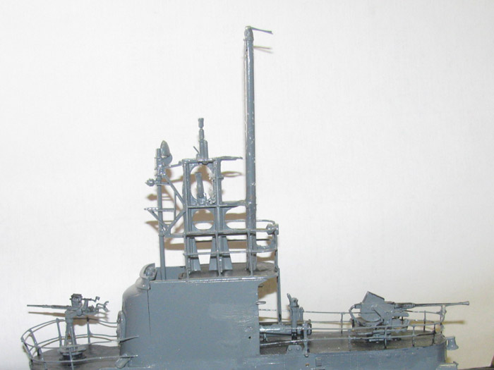
New periscopes test fit
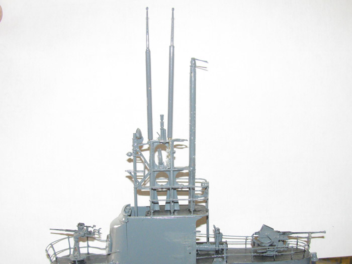
August 2nd =================================================
Finally after 3 months I am back in the shop.
Decided to put the center deck railings on.
First I have to make them.
I am using 1/32" rod for the stanchions.
They are 1/2" tall above the deck, so I cut pieces 3/4" long.
1/4" will go in to the deck.
They will actually go all the way through and I will be able to put
a drop of CA on the under side of the deck and add baking soda to stiffen
them up.
Here are the stanchions for one side.
The wooden block I made to hold the stanchions vertically and to the
correct height.
There is a groove in the wooden block that the stanchion drops in to.
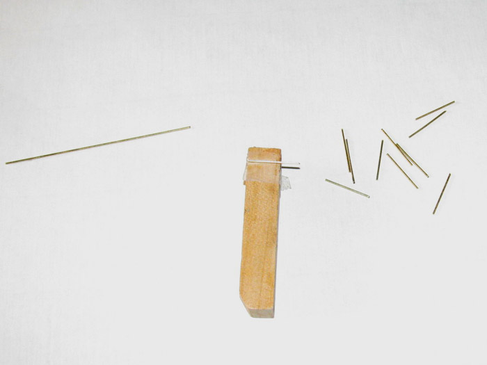
Installing the first stanchion using the wooden block.
A drop of CA on the end of the stanchion.
Hold for a few seconds.
Remove block and turn deck upside down.
A drop or two on the stanchion end sticking through the deck.
Sprinkle baking soda on CA.
Move to next stanchion.
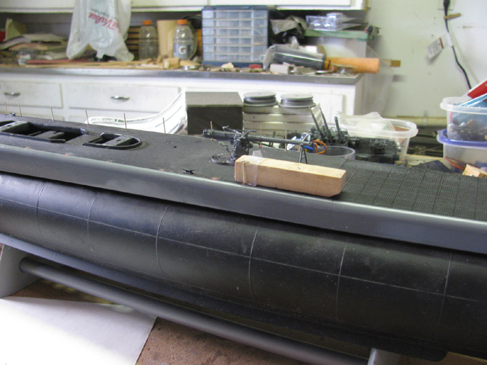
Taking my time, I installed the right side stanchions.
I decided to call it a day.
Now 9:15 am and it's over 90 F and rising fast.
Tomorrow I will continue the left side.
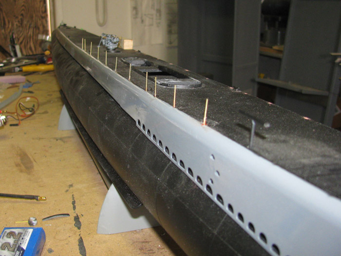
August 3rd =================================================
Got out to the shop early. (trying to beat the heat)
Before I started installing the left side stanchions, I looked over
the right side to see how straight they were.
A couple where not quite straight up and down.
With a little effort I was able to bend them vertically. (less than
1/8" for the worst one)
On to the stanchions.
Cut the needed stanchion pieces.
Got the wooden block and CA out.
And away I go.
In less than an hour, I had the stanchions installed.
Tomorrow I will straighten any stanchions that needed it.
I placed the deck on the hull and the tower on the deck.
This is where I am now.
I still have to make the gate stanchion support angle rods.
Going to find a photo to help me get the angles correct.
Then the top rail will be soldered on.
I did a test piece a few months back and it was not hard at all.
Just got to remember to use a heat sink on the stanchions as I go.
The lower rail will be a strong sewing thread.
I will use a slip knot on each stanchion so I can pull the line tight.
I will then use CA to harden the lines or I may just use the gray paint.
Maybe the gray paint is better should I have to do repairs later.
I made brass railings for the conning tower so I think this should be
easy.
It's all straight wire.
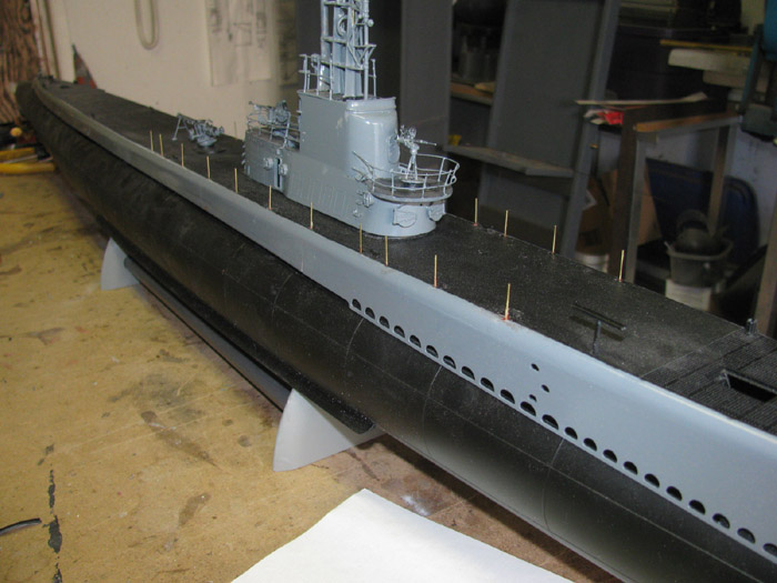
August 4th =================================================
Items to be made today.
Stanchion tension supports.
Stern gate supports.
Lower life line is in place but not permanent yet.
It has to go to the gate stanchion.
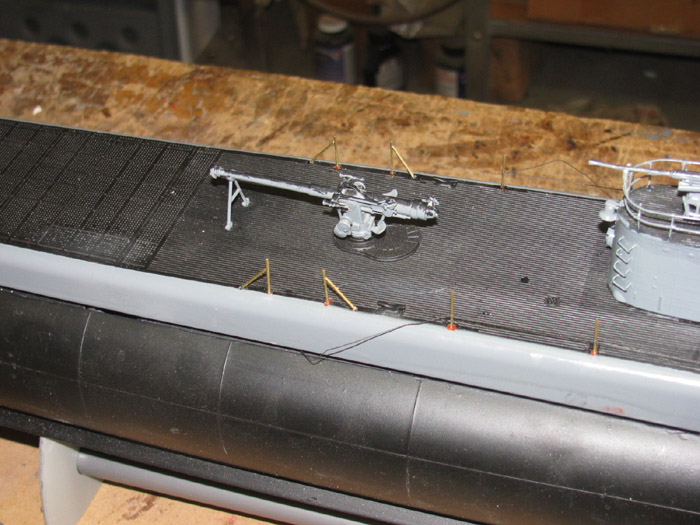
Bow railing end support.
This is incorrect.
The gate is 2 stanchion to the right.
The support is in place but not permanently installed.
Trying to decide if I want to remove it and make the correct gate.
? ?
The life line can be seen tired to the end stanchion.
The black thread does not show up well against the black deck.
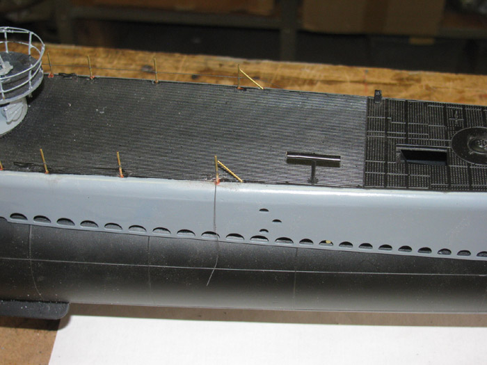
Here is a photo with the conning tower as a background to get the life
line to show up.
I need to go down the line and make sure the life line is at the correct
height from the deck.
The clove hitch knot will slit up and down but should not loosen up
as I work with it.
After I get the line set in place I will put a small drop of CA on
the knot at the stanchion.
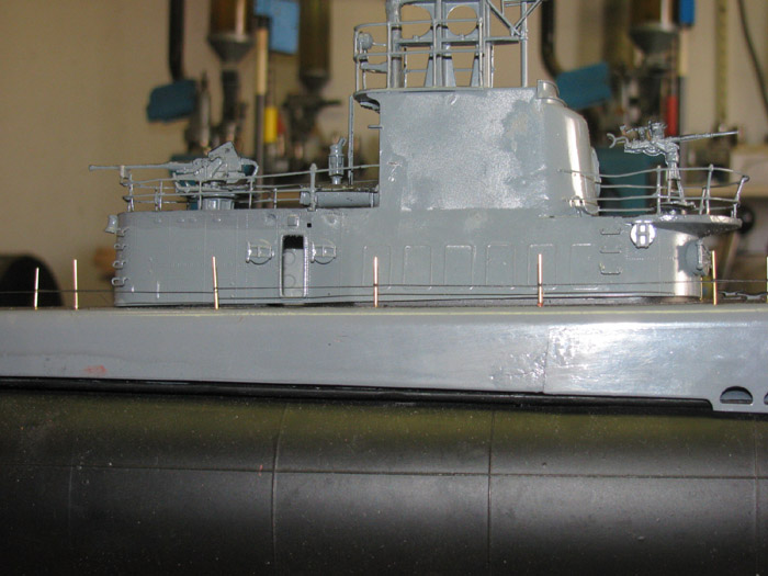
August 5th =================================================
I thought about the bow railing gate most of last night.
Well, the decision was to correct the railing and put the gate in.
Looked at photos and found a couple that show the listening tube goes
over the gate post.
Turns out the height of the railing post is just below the listening
tube.
That worked out well.
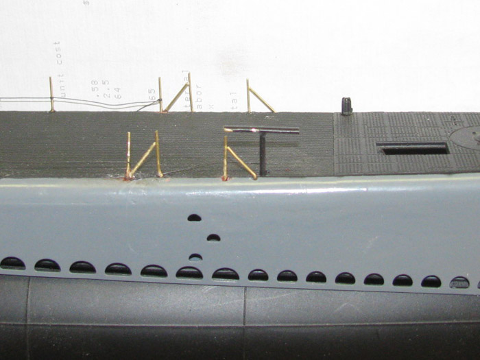
Working on the railing for the deck access stairs.
One fits, the other will need to be remade.
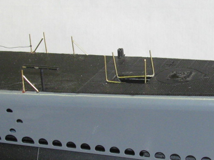
August 11th =================================================
Out to the shop to work on the deck railing.
I started by working on the thread lower rail.
Using Thin CA, I glued the thread to the stanchion and then soaked
the thread between stanchions to make it stiff and sag a little like cable.
I did 2 sections and then stood back and took a look.
The thread is too small in diameter.
It does not look right.
Well, on to another plan.
Remove all the thread.
Find the .032" diameter brass rod and go back to soldering the rod
on the stanchions.
Installed between 2 stanchions and stepped back again to take a look.
The rod is a little bit too big but it looks far better than the small
thread.
Okay.
Keep going with the brass rod.
After about an hour of soldering and cutting brass rod, I ended up
with this.
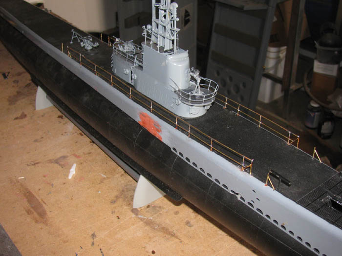
I need to go back and clean up a few solder joints that have too much
solder.
Do some touch up painting
But I like the look.
There are 2 spots I needed to glaze to fill hollow spots.
The painting will be to paint the sides gray again.
Let it dry a couple of days and then mask off the sides (gray) and
paint the flat black deck.
This will get the railings.
I think I will not protect the railing so it gets a little gray and
a little flat black on them.
August 12th =================================================
Cleaning up railings.
Sanding the deck and deck sides for repainting.
While sanding I found a spot that I must have touched with the soldering
iron.
I damaged 2 flood holes.
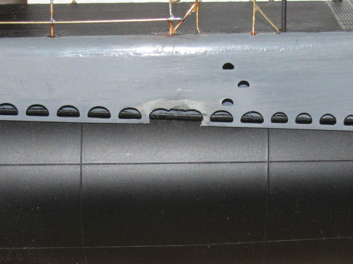
So I spent this morning building small parts to fix the flood holes.
This will be the backing for the glazing.
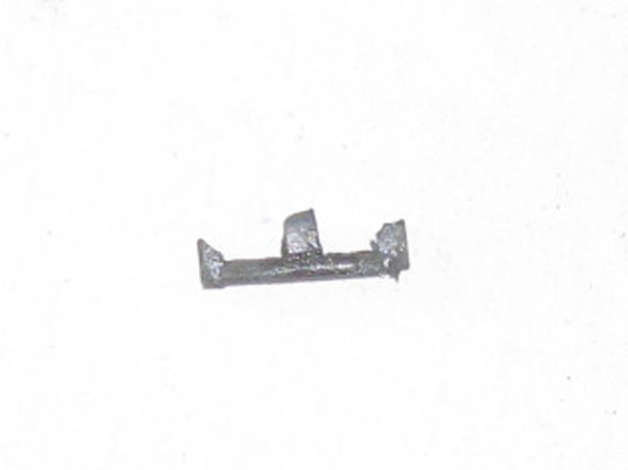
Backing installed
I will let this cure until tomorrow.
Then I will put glazing on it and let it cure.
Shaping after that.
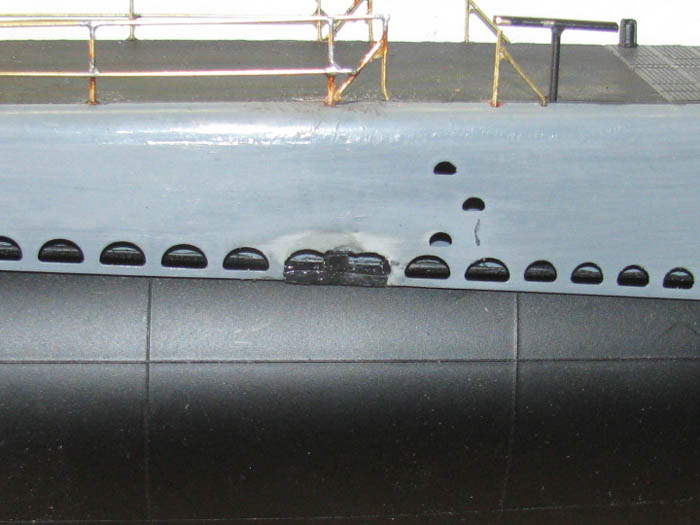
August 13th =================================================
Glazing was applied this morning.
5 hours later I sanded the side of the deck and smoothed out the glazing
over the damaged flood holes.
A little more sanding to get the black backing plastic down smooth
with the sides.
Then I will slowly cut the glazing out of the flood holes.
I will start smaller than the hole should be so I can use a small file
to get it to the proper size.
I think I will make a plastic peg the size of the other holes and use
it to check the new holes.
But it is too hot to do fine detail in the shop. 105 F.
In the early morning I will start.
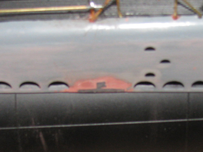
August 14th =================================================
Shaping the 2 flood holes has begun.
Using a small drill bit to make the entry hole and an exacto knife,
I have rough cut the flood hole.
After rough cutting the holes, I used thin CA to soak the glaze to
make it hard.
Now I can work with a small file to finish shaping.
I am not sure how I will deal with the deck frame which is very close
to the flood holes.
Maybe 3/32" behind the deck sides.
I will just take my time and do a little at a time.
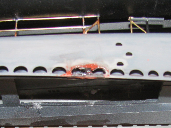
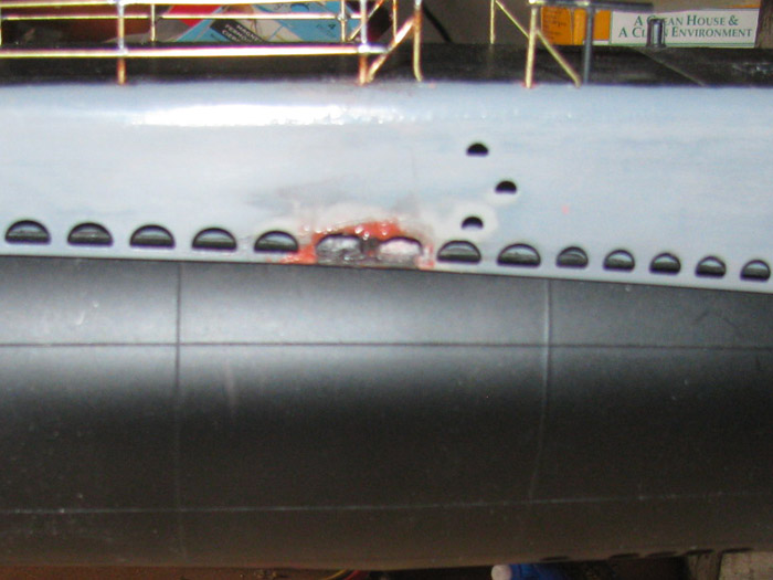
Back in the shop to make a wooden form to shape the holes.
Using a hard wood round dowel, I filed and sanded this former.
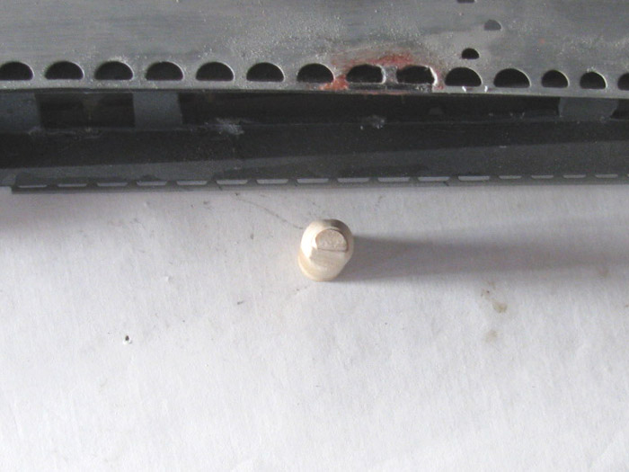
Here I am checking the shape and size against to the flood holes.
Being careful because there are two sizes here.
I need the larger of the two.
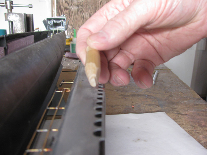
The wooden form fits tightly in an undamaged flood hole.
Next I will lube up the wooden form so the glaze will not stick to
it.
I may use CA and baking soda instead of glaze.
Glaze is very soft and I need the flood hole edges to be harder.

August 16th =================================================
Working on filling the damaged flood holes.
No photos
August 17th =================================================
Repainting the flood holes is complete.
Shaping and sanding done.
Sanded the entire deck sides for repainting.
Did a little work on one of the forward rail gates.
Files down the excess solder to make the rail smooth.
Wiped down all the parts.
Masking tape applied.
Out side to the painting station. (old cardboard barrel)
Smoke gray paint applied.
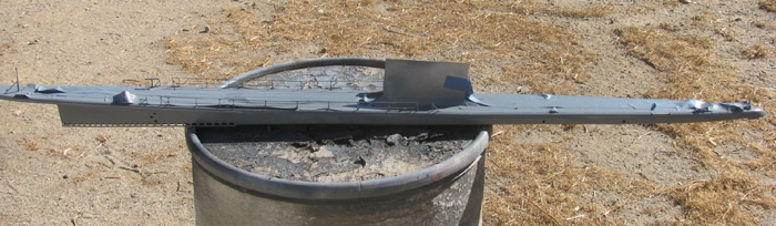
This is the side with the flood hole repairs.
Just left of the forward gate and off the barrel top.
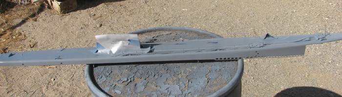
August 17th =================================================
Deck is masked and painted.
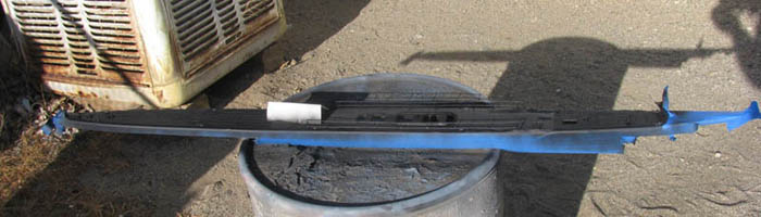
Deck moved in to shop and masking tape removed.
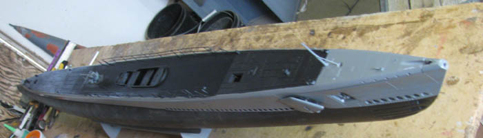
August 20th =================================================
Tried weathering the deck.
Failed.
Ended up repainting the flat black deck.
-------------------
Well, it is 100 F in the shop.
It is 105 F outside.
I did the finger paint smear test.
I rubbed it hard and nothing came off or smudged at all.
I stainless steel brushed the weathered spots.
Taped off the deck from the hull sides.
Took it outside and repainted the flat black parts.
5 minutes later brought the deck back in to the shop.
Removed the tape.
Looks like it did before I started weathering.
This looks much better to me.
While out there and before taping, I built the brass railing around
the forward deck access.
It looks good.
It got painted flat black.
After doing this which took about 15 minutes, I was done being out
in the heat.
=======================
Thought I would explain my problems with making the forward deck access
railings.
I used the original plastic parts as patterns.
I tried to CA the brass on to the deck ledge.
I got both U bend pieces of brass glued in place.
But every time I touch those parts, they would break loose.
These became such a problem, I had decided to leave the railings off.
But without the railings, it does not look right.
Then I was repairing a side railing that needed to be refitted on the
railing post to be straight.
At this point I had a thought!
The issue is the CA does not hold the brass to the plastic very well.
It's a small little ledge.
The thought was to make 4 posts.
Cut them long and bent them to the correct height and leave room for
the top railing.
I drilled holes for the posts in all four corners.
Actually 2 corners had a notch filed in for the posts.
I bent the posts so they would go through the deck and to the under
side of the deck.
I pushed the post though from the under side.
Holding the post straight with the bend tight to the underside of the
deck, I put a drop of CA on the bend to hold it in place.
I did this to all four post.
I then added more CA to 1 post at a time and sprinkled baking soda on
the wet CA.
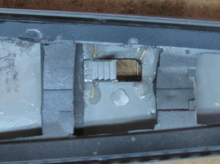
They are now set very strongly in to the deck.
Next I cut and soldered the top railing to each post leaving the aft
end open to the ladder.
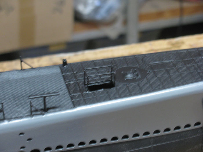
August 21st =================================================
Time to return to building the electronics tray.
I am going to have to decide on a ballast system.
I have the following that might work.
1. I have the water pump and ballast balloon system I took out of the
Skipjack to put in the piston.
2. The same pump can be used to pump air in to the ballast tank through
the snorkel.
This would use an internal ballast tank to hold the air.
I can make a vent valve on top of the cylinder.
I can use the pump to pump air in and out of the tank by placing the
pump pickup near the top inside the ballast tank. (1 less servo)
3. I could look for an air pump that pumps volume and is smaller than
the Skipjack pump. (it barely fits and has to sit at an angle)
I am going to work on the forward electronics tray.
This has the bow planes retract and pitch servos.
It will also have the battery tray.
And I am thinking I will add another servo that will move the battery
tray about 1.5" forward and backwards for trimming under way.
The reason is, I watch other long thin boats and they seem to have
problems trimming surfaced and submerged trim.
There is a 7' Type VII run at our gathering and it has and actual water
ballast trim tanks where it can move water inside the cylinder
back and forth to lever the both. This is separate from the main ballast
system which happens to be 2 ballast pistons.
I may not be able to work on the boat for the next few days, so I will
do a little research on the small air pump and see what I can find.
I though I had 1 of these pumps but I have looked and looked with no
success.
Might of been one of those parts I thought about buying and then bought
something else.
I did find 2 different inline check valves.
I originally wanted to make the ballast system a negative system.
I may still do that but right now, it looks like I may trim the boat
with 1/2" of the sail above the surface and use the bow planes to dive
the boat.
This will be decided when I get to making the 2 ballast tank frames
that go inside the cylinder.
considering 2 options.
1. A small diaphragm in 1 of the tank ends or make 1 end move back
and forth like a piston. Travel about 1/2" is all that is needed.
The diaphragm would be the easiest to build, I think. Just a servo
and a can to move it back and forth.
==================
This morning I did place the cylinder in the hull and move it around.
I think I found where I want it to be and have room for the controls
coming out of both ends.
The controls in the stern, propeller shaft, rudder and stern planes
control rods.
The rudder and stern plane controls move so easily, I will probably
use magnet links.
The bow planes and retract are much harder to move so I think they
will be direct connect with wheel collars.
Unless I can figure out why they are so much harder. (most likely the
gears on the retracts and the extra linkages on the planes rotate.
This is not hard to do, just got to get the electronics trays setup
and then make the linkage up.
August 24th =================================================
Made it out to the shop.
Want to work on the rear electronics tray.
Test fitting what I have.
The propeller motor sits too low.
It needs to come up to almost center of the end cap.
The end cap needs to be finished.
The o-rings I have now do not fit.
The groove is not deep enough.
I left it that way when I made the end caps because I did not have
o-rings to test fit.
Both end caps are done and the o-ring sits perfectly.
I can insert the end caps in to the cylinder without using a tool to
push the o-ring down to keep it from pitching.
I just need to rotate the end cap about 1/4" and the o-ring will slide
in t the cylinder.
Back tot he main motor alignment.
This is the tray as it was before I started this morning.
The edges are rolled under about 3/16" to stiffen the tray.
The edges touch the cylinder and will not let it drop any lower.
Okay, the solution is to cut the rolled edge off.
File and clean up the edge.
Go out to the big vice and rebind the edges.
It will be a little harder this time because the motor bracket is bent
up and will interfere with the vice jaw.
So I will butt it up to the side of the vice and slowly bend the edge.
WEll after about 20 minutes, I have new edges on the tray.
Test fit shows me that it will drop more than enough to center the
motor shaft in the end cap.
I did remove the motor and servos so there was nothing on the tray
while I worked on it.
I will clean the aluminum up with a belt sander tomorrow.
I will need to cover my face so there is no dust or dirt to get on
my face cuts.
After cleaning up the tray, I will make a small bent bracket that will
mount on the end cap.
The tray will mount to the bracket with 2 stainless bolts.
Same in the Skipjack, 2 modifications back.
Once I get the brackets made, I can measure and locate where to drill
holes for the shaft and 2 control rods.
I will drill holes for 1/8" brass tubing.
There will be the control rods and shaft bearings.
The shaft bearing will only go through the inside half of the cap.
On the outside of the cap. I will use the brass tubing to guide my
cutter for the cap seal.
The propeller 1 to 2 gear box will be over the cup seal and keep it
in place.
The control rods will be over the gear box and not thought the gear
box.
Once I get the brass tubing in the end cap and the cup seal, I can start
aligning and installing these equipment on to the rear tray.
The tray is now 1/4" narrow in width.
About half the distance from the edge to the motor bracket on each
side.
August 25th =================================================
15 to 20 minutes in the shop.
Built a connector for the main motor to propeller shaft.
The motor shaft is bigger than the propeller shaft.
So 2 different sizes of brass tubing were used.
The large tube fits the motor shaft. (tightly. required a little filing
to make it fit)
The small brass tube has an inside diameter of 1/8" to fit the propeller
shaft.
I fit the small tube in side the larger tube.
I cut the large tube to the needed overall length.
Cut the small tube to half the length.
Soldered the small inside the large with one end flush.
Using drill bits, I cleaned out the solder excess.
There was not much.
Places the connector tube in to the small vise.
Using the wheel collar that fit over the outside tube, I drilled very
small holes in the tube at each end through the set screw hole.
The drill bit was smaller than the thread to avoid damage.
I left 1/8" of tubing sticking out past the wheel collar.
Removed the wheel collars and proceeded to drill holes large enough
to allow the set screw to go through.
With the wheel collars on the connector tube, the set screw goes through
and tightens on the motor and propellor shafts.
The set screw keeps the tubing from spinning free.
checked the alignment of the motor and propeller shafts bu turning
the motor case.
I see that the 2 shafts are straight and no wobble.
I can now mark the cut line on the tray.
To the right is the 1 to 2 gear box with gears removed.
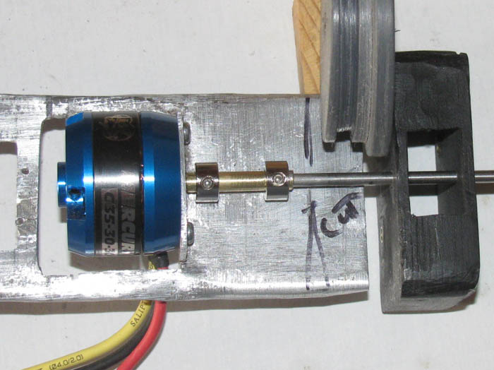
August 26th =================================================
Cut the tray on the aft end that mounts to the end cap.
Made the bracket that will mount to the end cap and then to the tray.
Bent a 3/8" aluminum angle that will fit across the end cap with room
at each end.
Drilled holes for stainless bolts in the bracket and the tray.
About 1/8" in diameter.
Will pick up stainless bolts and nuts when in town later this morning.
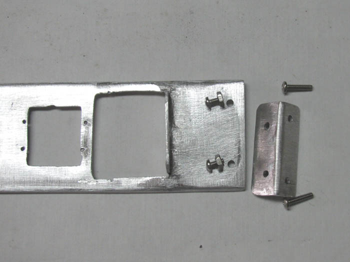
Made the propeller shaft bushing/bearing that goes in the end cap.
It will stick out about 3/8" in to the cylinder.
The other side of cap will have a recess cut in for the shaft cup seal.
The bushing fits in the center of the cap where I have a 1/4" hole
for the bolt that is used to turn the caps.
I place the brass tubing bushing in my small vise and place a piece
of tape over it to use as a seal on the bottom of the cap.
This will keep the glue from running through.
I place the cap over the bushing tube and center it.
I tape the cap in place to the vise.
Now I can drip glue in the large hole holding the vise on an angle so
the glue will run down between the bushing and the cap.
This will sit over night before I drill the excess glue from the bushing
tube.
Once I get the end cap flat, I will use my seal cutter to make the
recess seal shoulder.
This all sounds complicated but it took 10 minutes to set up after cutting
the bushing to length and cleaning it up so the shaft runs smoothly in
it.
While out in the tool shed, I got out the belt sander
Placed in in the outside big vise.
Sanded the tray to make it clean and have all the sanding marks going
the same way.
I have not yet cut the tray to length as I do not know exactly where
I will be placing the other equipment until I get the bracket and end cap
mounted to the tray.
Do a little every day and it will all get done.
----------------------------
But this Wednesday and Thursday I am at the VA hospital.
Wednesday is to check on healing progress on my face and nose.
Thursday is optometry and most likely eye exam for new glasses.
I hope so.
The healing is coming along and I have been able to get out in to the
shop and work on the boat.
Feels good even though I can not stay out there very long.
It is within my 10 minute minimum work per day.
Actually, I have been getting 30 minutes to 90 minutes per day.
------------------------------
Back from town with the bolts.
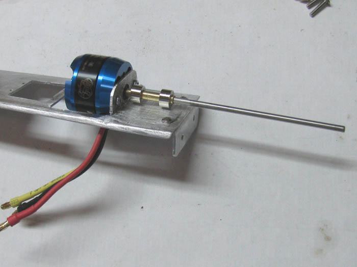
August 30th =================================================
Got the end cap drilled and the propeller shaft centered and glued in.
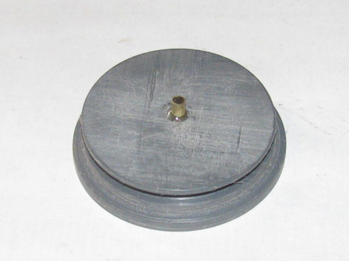
Put CA on the railing gate wires.
Once it hardens, I can warm them up and shape them in to a better curve.
Bow.
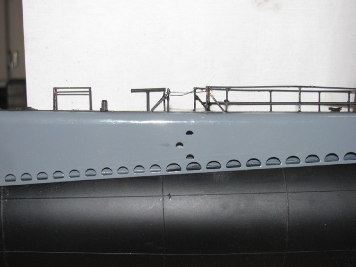
At gun deck.
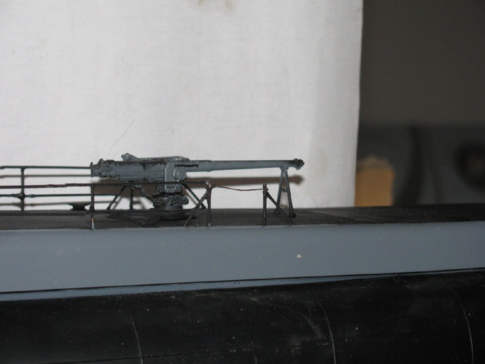
August 31st =================================================
Today was mostly a loss.
I spent over an hour looking for my seal cutter.
I have not found it yet.
Option 2 is to make another one tomorrow.
Got tired of looking so I moved on to other things.
I need to decide on what seals for the control rods to use.
Choices are o-rings or bellows.
I use both and I like both.
Bellows are easier to install.
O-rings require less room and more maintenance.
If I have to make new cutters, I will probably go with bellows as they
only need a holes drilled through the cap to get the brass tubing through.
No cutter required.
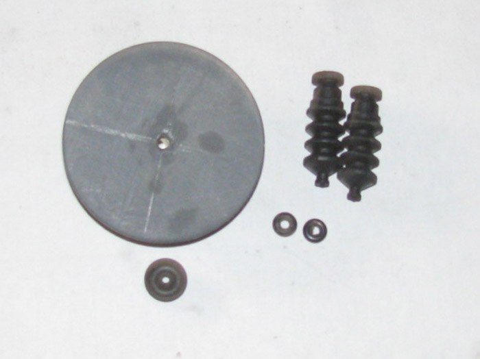
I shaped the 1 to 2 gear box to fit the end cap curve.
Reinstalled the gears and fit it to the end cap.
The shaft hole is slightly off center. Less than 1/32".
Found center and marked the cap.
Test fit to cap.
Need to get 2 stainless bolts to mount the gear box to the cap.
I clamped the gear box to the end cap and everything turns easily.
Need to mount electronics tray bracket to the end cap.
I now know how much propeller shaft is needed and can cut it to length.
I thing cutting it with 1/8" sticking through ought to do it.
The end cap will hold the propeller shaft cup seal in place once I recess
the seal.
Works well on the Skipjack. (re grease once a year has worked)
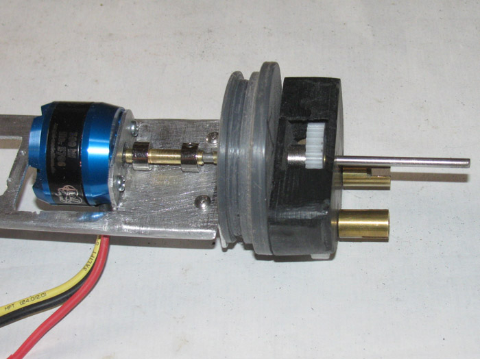
September 1st =================================================
Make cup seal cutter.
Shape piece of 1/4" thick flat bar by cutting and turning in drill
press to get correct diameter.
Take to outside vise and file cutting edge on bottom of cutter piece.
Find a scrap piece of end cap for testing cutter.
This is to make sure the diameter is larger than small end of cut and
smaller than the large end of cup.
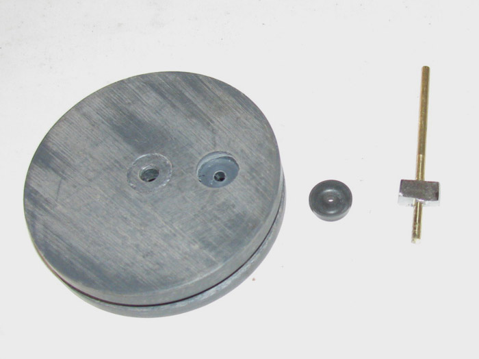
Cup drops in to recess but stops about 1/3 of the way down.
Putting pressure on the cut and it will go to bottom of recess squeezing
cut sides to end cap.
In the photo the cup sticks up above the end cap.
This is to allow the gear box to compress the cup in to the recess
when gear box is installed.
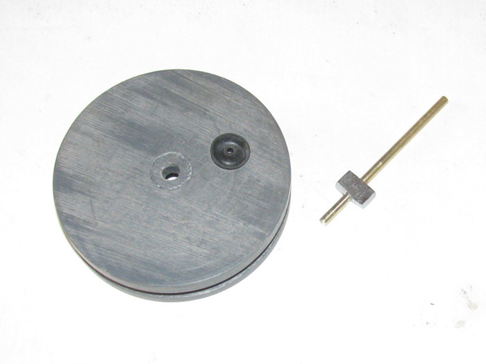
September 2nd =================================================
This morning, I have cut the recess for the propeller shaft in the end
cap.
Took my time and went slowly.
Got it to the correct depth in 4 passes. (always worry about going
too deep)
Assembled the gear box to the end cap to decide where I want the control
rod bushings.
Well, it is obvious that my plan to have the servo horns under the
main motor will not work.
I would have to go through the gear box.
I am going to have to install the servos with the arms on top.
Bend some control rod to see where they will be to clear the main motor.
Going to decide if I will use 1/8" brass tubing to go through the end
cap or try using 1/16" brass rod.
Need to cut several sizes of tubing to size down to the control rod.
Oh, I decided to go with the bellows to seal the control rods.
It appears that is what I had planned in the beginning.
The bellows where sitting in the parts to be used container.
No small o-rings.
Even had the through end cap brass tubing cut to size already.
The end cap is sitting in the small bench vise.
I had drilled small guide holes some time back.
I filled them with CA in layers using baking soda as I went.
To make sure it all cures, I will give it overnight.
Then after test fitting the control rods, I will drill the holes again.
Every day a little progress.
September 3rd =================================================
Through end cap parts have been cut to size.
Locations for the through cap holes have been measured and drilled.
Bellows have been put on tubing for measuring.
2 control rod bushings (bellows) and 2 pump air tubes.
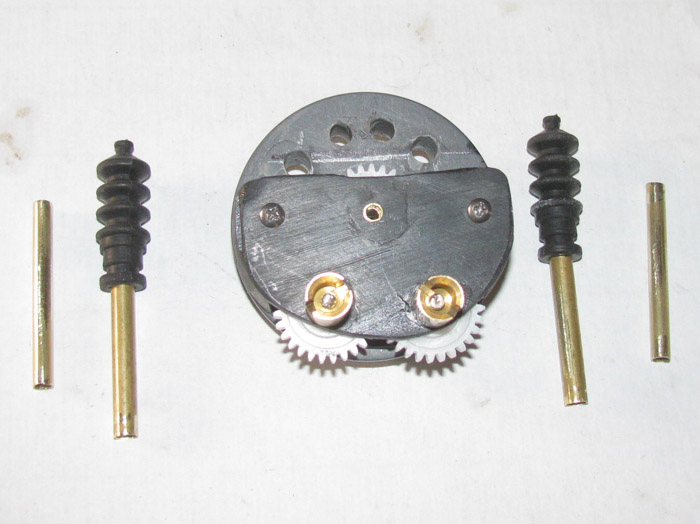
Test fit all the tubes through the end cap.
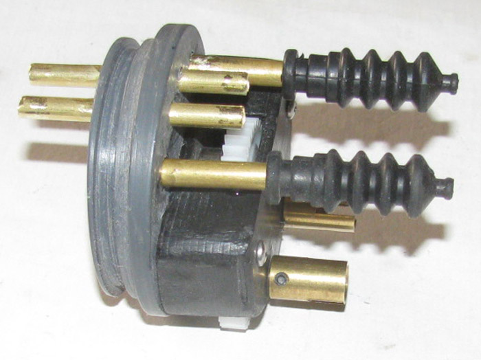
All tubes CA in place.
Will apply second time with thin CA to make sure it gets in to any
voids between tubing and end cap.
You can see the gaps in this photo.
This is what the completed read end cap will look like.
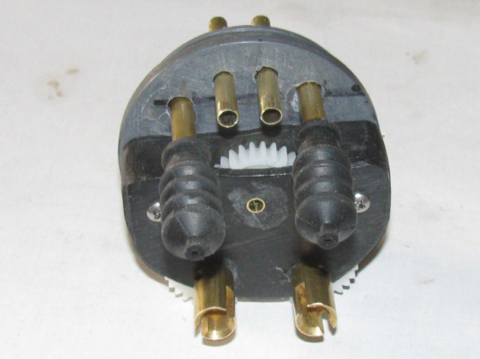
September 4th =================================================
The control rod reducers have been cut and assembled.
The 2 pieces with short tubes on the ends to fit the end cap through
brass tube. (1/4" down to 1/8")
They went inside the control rod brass tubes. (the 2 top long ones)
Control rods have been measured and assembled.
I need to make 2 tubing rings to go on the ends of the control rod through
tubes.
They will help keep the bellows from sliding off.
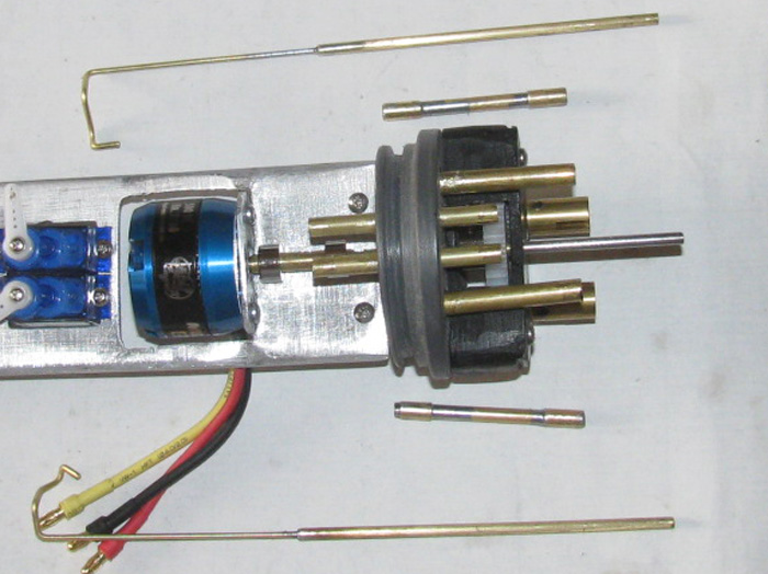
September 5th =================================================
I have finished making the control rods and assembled everything.
The important thing to remember, this is a brushless outrigger motor.
The case rotates when running.
The control rods had to go around the motor case and not touch it when
at full throw each way.
The end cap is complete and only needs to be disassembled to add the
cup seal for the propeller shaft and grease it.
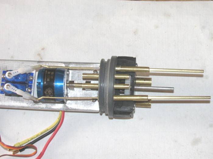
Moved on to the front end cap.
I needed to get (for now) 2 control rods and the Schreader valve installed.
Also had to fill the center hole used to turn the end cap.
Now to let it cure over night.
Build control rods tomorrow.
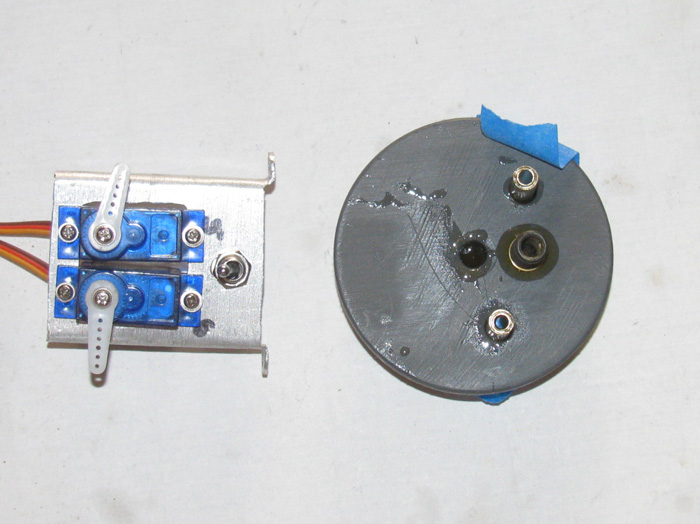
Second view.
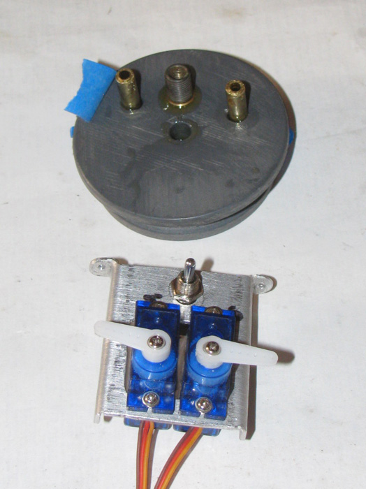
September 6th =================================================
Front end cap assembled.
This would be the bow planes retracts and pitch control servos.
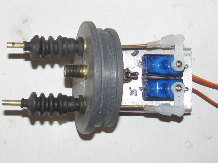
I am now working on the control rod connections to the bow plane and
retract control horns.
Not much room in there to work on things.
So far it looks like I may have to remove the retract controls
and move the horn back to get a better angle on the horn.
The horn is almost horizontal when the bow planes are lowered.
There will not be enough force from the servo to hold the bow plans
level during operation.
Remove and resoled the horn.
Rotate back about 10 degrees.
September 11th =================================================
Dropped the cylinder to the hull between the stop blocks.
Cut the bow plane control rods.
Soldered wheel collar to bow planes control rods.
Adjustments can be made by loosening the wheel collar and moving the
bow plane control rods on the servo control rods.
I see the bends are not very neat but that can be fixed later.
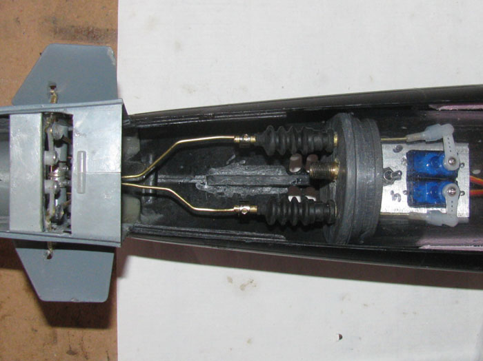
A view up in to the bow.
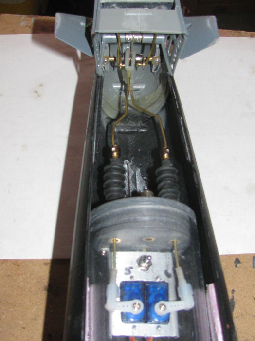
September 25th =================================================
Lots of little things have been done.
Here I am working on the propeller shaft dog bones.
Measured and cut brass tubing for the extension.
I know, others have used aluminum.
I have aluminum tubing but it oxidizes so quickly, I thought I would
go with brass.
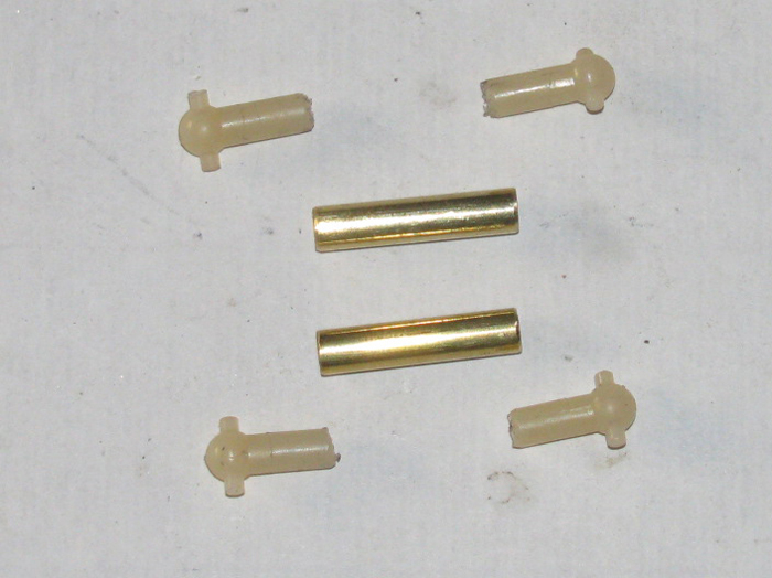
Assembled with CA glue.
Now I have to drill and pin each end with a brass pin.
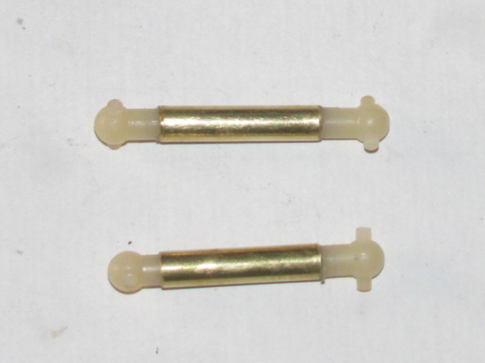
Right side dog bone installed. (not pinned yet)
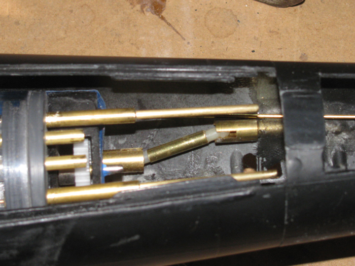
Left side dog bone installed. (not pinned yet)
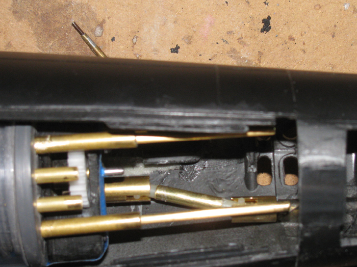
Tested the turning of the gear box and propeller shafts.
All is good.
Now to remove and pin the ends.
To install the dog bones, I have to remove the dog bone connector on
the propeller shaft and slide the shaft back out of the connector.
I spent a lot of time trying to drop the cylinder in and align the 2
dog bones at the same time.
I gave up.
Sliding the shaft out is relatively easy.
A couple of minutes and it's out and back in.
========================
Later today.
Installed control rods to the rudder and stern planes.
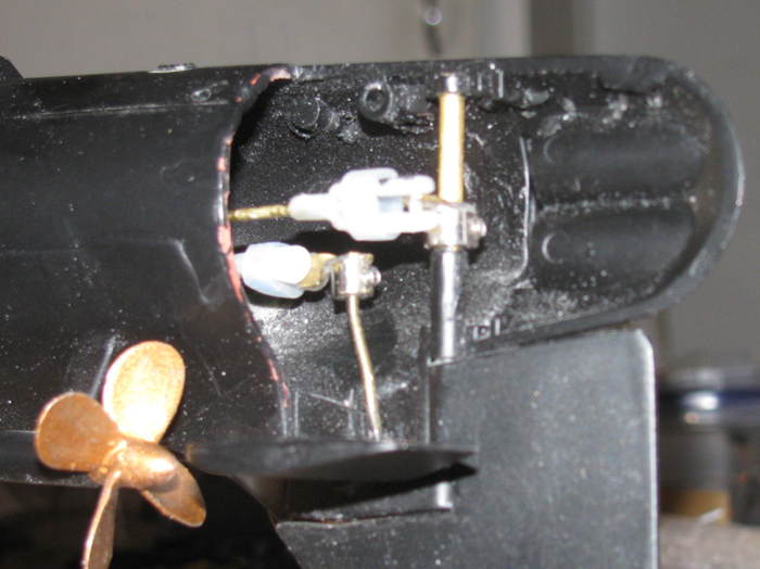
Made up the connectors on the control rods to the servo control rods.
The bellows are not installed yet.
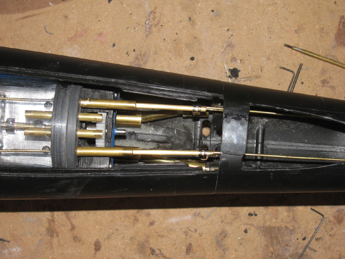
Another look at the bow control rods in place.
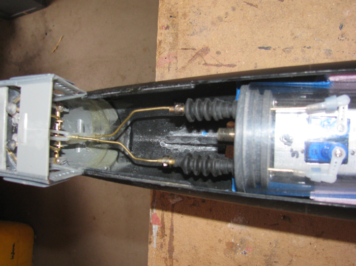
This means the control rods for the
Rudder
Stern planes
Bow retract/deploy
Bow planes dive/rise angle
Propeller shafts and connectors
are complete.
They will need a little bit of adjustment once the radio Rx is installed
and I can test them for travel.
Back to working on the electronics tray.
September 27th =================================================
I have not been in the shop the last couple of days.
Doing other stuff.
I did get out there a little while ago.
Got 20 minutes of work done.
Back in December, I made the transportation box badge. (6" long)
I also made the smaller version that would go on the transmitter carrying
case. (4" long)
I was looking at the Tx cases sitting on the floor and decided I was
far enough along to install the GATO badge on the Tx case with the Tx I
will be using for the GATO.
Did some measuring to get the blue stripe the correct size.
I decided to make the GATO on the surface and not submerged like the
nuke boats.
I can now make the rear deck gun and install it for effect. (it may
just be painted on)
A little touch up on the blue paint and I think this is good to go.
Note: the badges are not to scale. The Tx case badges are all 4" long
as the transportation box badges are all 6" long.
Something got done today. --- progress how ever small is progress.
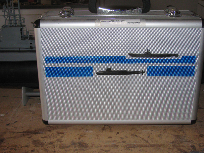
September 28th =================================================
Tx case paint touched up and cleaned up.
Cut sheet plastic squares to make bulkheads for ballast tank.
The frames are 2 and 3 sheet thick.
1 frame consists of 5 pieces.
There are 4 each of 2 pieces and 2 each of 3 pieces.
Each frame have 2 pieces on each end that fit the cylinder closely.
Between the 2 end pieces will be a 3 layer piece where the o-ring will
go.
When I turn these, I will turn them all together.
Once I have them fit the cylinder, I will take the 4 ends pieced off
the shaft and continue turning the 2 remaining pieced down for the o-ring.
Once I get the o-rings to fit, I will bond the ends to the centers
making 2 ballast tank end frames.
I have 1/8" brass tubing with brass bolt threads soldered in the end
to use as spacers to keep the frames apart.
In the shop the sheet plastic pieces have been covered with cement and
place on the table with a block of wood on top.
5" C clamp pressing the pieces together for a good bond.
Will let sit for a few hours, maybe over night.
Don't what the pieces delaminating when turned.
======================g====
Later in the day....4pm.
I was out in the shop to check on the plastic bonding for the ballast
tank frames.
They look good and will be ready to work in the morning.
Will measure and mark a center to the pieces.
Drill a 1/4" hole for the bolt to go through that I chuck up in the
drill press.
I will hand cut the squares in to circles by cutting on the line made
using the test section of cylinder.
I will hand cut to the line which is the outside line of the cylinder
and I will turn them down to the inside line in the press.
I will test fit them when I get close so I do not under cut the size.
I will remember to take photos of this process.
Build stories are not much fun without photos.
September 29th =================================================
In the shop working on making ballast tank end caps.
Here are the plastic squares under the blocks of wood having been compressed
over night while they cured.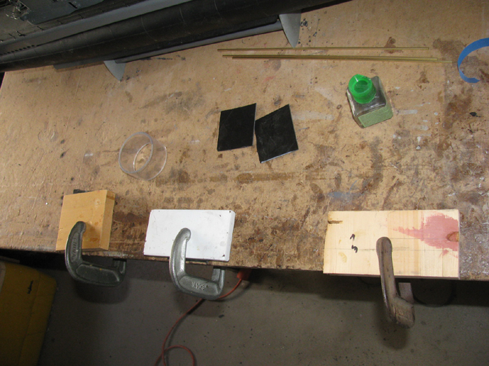
Removing the clamps.
Under each clamp where 2 sections for the frame.
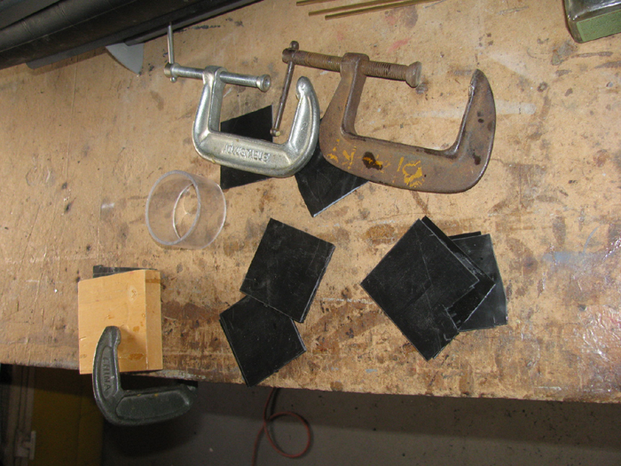
Took the sections out to the tool shed where the drill press is.
Marked the squares and drilled a 1/4" near center of each square for
mounting on the bolt.
Using the band saw in the upright position, I cut the corners off each
square to help with the turning.
The cutter tends to catch on the plastic if it is straight out.
Time to put the pieces on a 1/4" bolt and chuck them up in the drill
press for turning.
I am going to start by turning all 6 pieces at once to the size that
just fits inside the cylinder.
Here I have turned all the pieces down to where I have a smooth edge
on all pieces.
I can now work to get the outside diameter down to slip in to the cylinder.
As tight as I can get it without binding.
The plastic disks should slide in with no effort but as small a gap
as I can get.
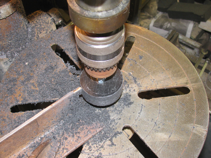
I make a cut or two and then test fit.
I have to do this several times as I do not want to over cut the parts.
Here the stack of disks just slip in to the test section of cylinder.
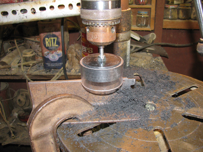
This makes the 4 side pieces of the frame the correct size.
I now will remove all the disks from the 1/4" bolt and put the 2 center
(3 layers of sheet plastic) back on the bolt.
I will turn these down until the o-ring put on the disks will fit tightly
in the cylinder section.
This requires several tests as well because over cutting required new
disks.
In the photo,
Left are 2 baffles for inside the ballast tank.
Center are the parts to make 1 end cap and the o-ring is sitting on
the ledge gap on the top part.
Right are the parts to make the second end cap with no o-ring sitting
on it.
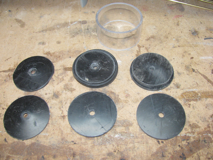
The parts have been cleaned up and sanded.
Cement bonder has been applied.
The disks have been placed on a 1/4" shaft to center everything.
The parts are now sitting on the bench with a 1/2" steel block sitting
on top of the plastic pieces and a 5" clamp has been tightened down on
the whole lot.
I will leave over night to cure.
Once the frames have cured, I will test fit in to the cylinder with
the o-ring installed.
If I need to, I can put each part back in the drill press and turn
the center deeper with a jeweler file.
I do not think I will have to do that but I have done it before to
get a better fit.
October 1st =================================================
Today started by removing the new ballast tank frame.
Everything looks good.
Did a little 200 grit wet/dry sanding on the frames.
Go my small wooden stick out and wrapped it with 200 and did some sanding
in the groove keeping the groove square.
Cleaned up the frames and put on o-ring in the grooves.
Installed it in to my short test cylinder piece.
Put my finger over the 1/4" hole on one end and blew in to the other
end.
Good news....No leaks!
On to the ballast tank long rod spacers.
Here are the parts
2 end frames
6 brass nuts
6 brass washers
2 long brass bolts which I will cut 3 pieces from each bolts.
3 1/8" - 12" brass tubes
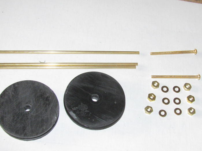
I cut the long brass bolts in to 3 pieces each.
I put them in the drill press and turned one end down to fit inside
the 1/8" brass tubing.
Cleaned up the other end so the nuts would go on smoothly.
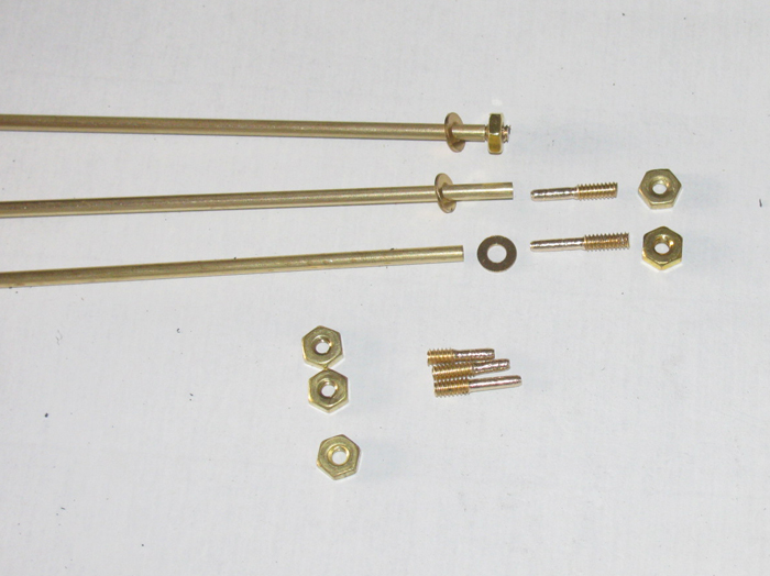
I cut 6 pieces of tubing that slips over the 1/8" tubing to use as a
stop for the washers.
Using my small table vise, I soldered the stop tube and washer to the
long 1/8" tubing holding it at the correct distance from the end of the
tubing.
The bolt has not been install at this point.
Soldering the spacer and washer took a little effort.
I made a short larger tubing to slip over the 1/8" and hold the washer
lever on the 1/8" tubing.
This washer is not going to touch the frame end.
An o-ring will be between the washer and frame end cap.
This will make the ballast tank water and air tight from the rest of
the cylinder.
Next project will be to determine where to drill the 1/8" holes through
the end caps.
I think I want 2 near the bottom and 1 at the to, evenly spaces in
1/3s around the cap.
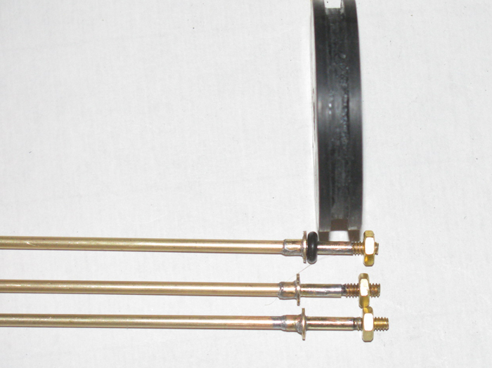
October 2 =================================================
Put the frame disks back on the 1/4" bolt to keep the disks aligned.
Drilled the first 3/32" hole at the point that will be the top of the
disks.
Then drilled the other 2 holes
The 2 frames between the ends are to slow down slosh in the cylinder
when not full or empty completely.
The 2 middle frames have a flat side to let air and water past which
needs to be at the top.
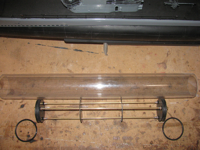
A side view where you can see the slots in the middle disks that allow
me to put them on the brass frame tubing.
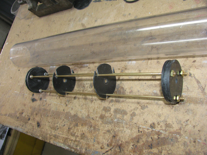
I slide the ballast tank frame assembly in to the test long cylinder
with the end cap o-rings not installed.
This gives me approximately 11.75" of inside ballast tank length.
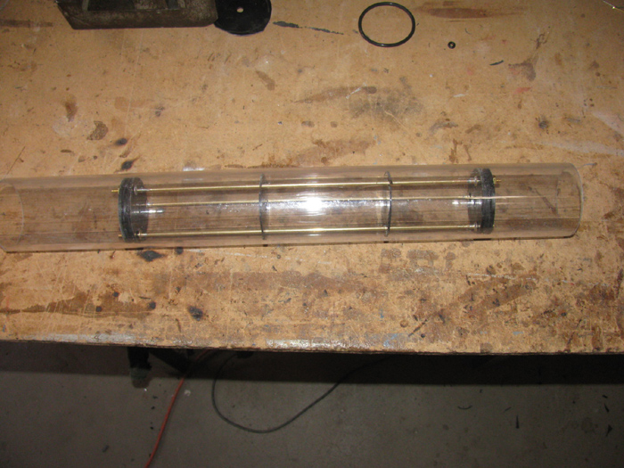
October 3rd =================================================
More work on the rear electronics tray.
Today, I made the bracket needed to hold the ballast water pump.
It is on a slight angle to fit in the cylinder. and not have the motor
shaft hit the cylinder wall.
Rx is mounted between pump and servos.
This position makes it easy to plug in all the servos and esc(s).
This is the top of the tray.
The fail safe will mount to one side of the Rx and the pitch controller
will mount to the other side of the Rx.
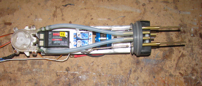
This is the under side of the electronics tray.
The main propeller motor speed controller will be mounted on the bottom
of the tray.
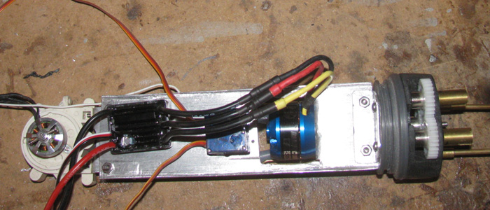
I have test fit this unit in to the cylinder and it looks like it will
all fit with out further adjustments. (hope)
It also looks like I have gained more free space by about 1.5" .
October 10th =================================================
Here is the electronics tray in progress.
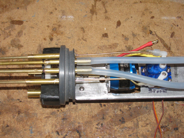
Yesterday while working on this I noticed that the inlet/outlet hoses
can and will touch the motor case.
This would be a big problem.
To eliminate this problem, I decided to extend the brass tubing out
past the end of the motor case.
This is a simple fix as I just needed to slide the next small brass
tube in to the original tubes going through the end cap.
I used an expanding glue to hold them in place.
This is what I have now.
This gives me abut 1/8" clearance above the motor case.
This will not interfere with motor removable because the motor comes
out through the bottom of the tray.
The servos I thought would be a problem but they will tip enough to
also come out the bottom.
If I need to, I can cut the tubes a little shorter to get the servos
out and still clear the motor case..
The Rx was moved to the under side of the electronics tray.
The speed controller is not on top. (it required less room letting
the hoses lay down better.
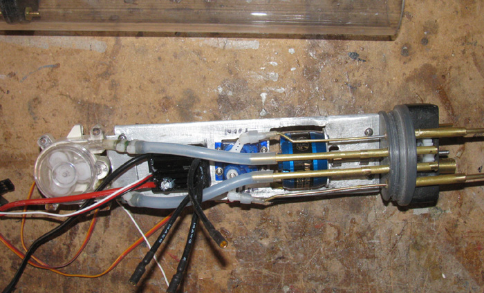
October 11th =================================================
Here are the (right to left)
Rear electronics tray
Ballast tank frame
battery
Front electronics tray
sitting next to the cylinder.
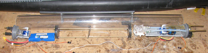
Here are all the parts in the cylinder.
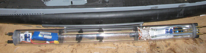
On to running servo wires and main power wires.
October 13th =================================================
subnormal will be having their gathering this coming October 26th.
I am not sure if the Gato will be ready to run but it could be ready
to show. (waiting for parts)
I thought while charging Skipjack batteries, I would see what is needed
to get the Gato transportation box finished and ready.
Looked it over and found I had only the foam block that the conning
tower will be on for travel.
The box would have been very tall had I made it to handle the assembled
boat.
So I decided to transport the boat with the conning tower removed from
the deck
This still makes the box tall.
The hull and deck are fine but the conning tower and it's mast are
the issue.
The after mast is my snorkel and I do not want to remove it and have
to deal with air tightness.
The 2 periscopes on the other hand could be made to slip in and out
like all my other periscopes.
By removing the 2 periscopes, the transportation box is now a manageable
height.
Cut a foam block that fits tight in to the underside of the conning
tower.
Put the hull and deck in the box to see where I might put the tower
so it would not interfere with the hull or the box sides.
Up by the bow seems to be best because the bow is thinner than the
stern.
Found the position for the tower so I can still get my hand down in
the box and under the bow to lift the hull out.
The 2 periscopes will be put in to 1 of the hull hold down foam block.
For my other boats, the periscopes sit on the hull foam block bottom
but they tend to move around and fall to the bottom of the box.
I am going to photo the placement of the boat in the box ready for transportation.
Assembled boat.
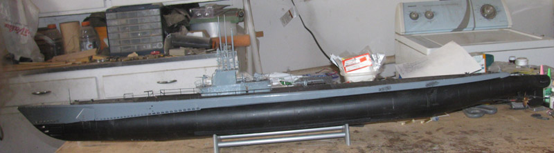
Open transportation box.
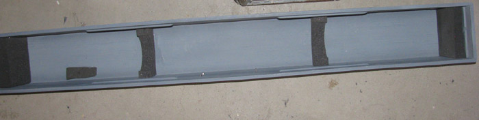
Remove the 2 periscopes.
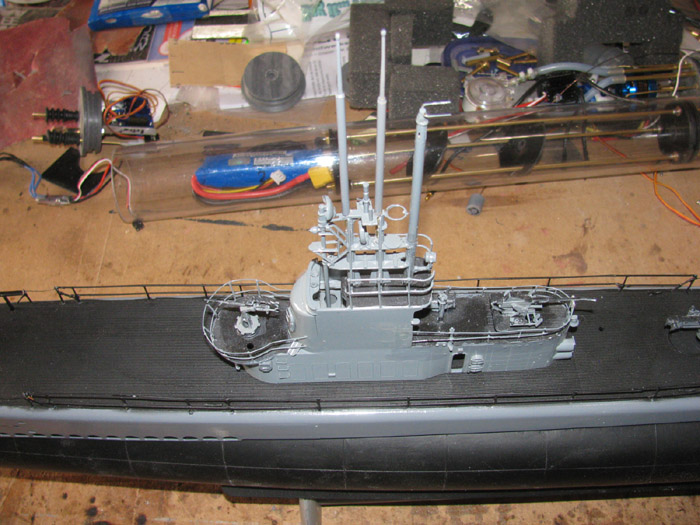
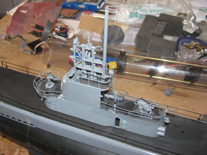
Place mast in to foam hold down block.
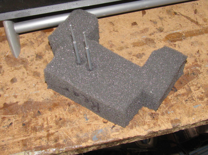
Removing the tower which is held in with 2 small bolts from under the
deck.
Place the conning tower in to the box on foam block.
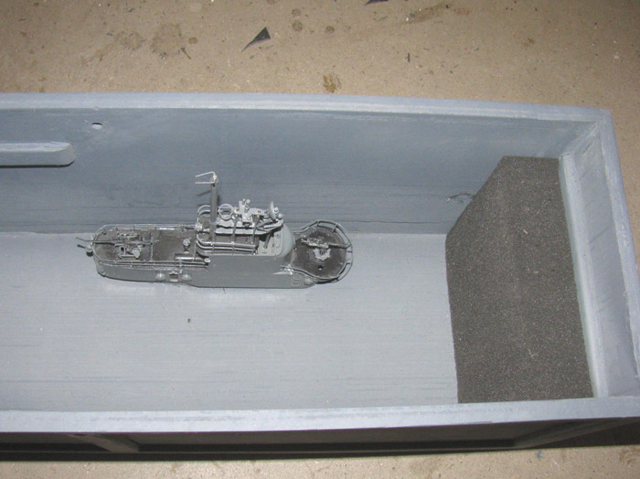
Boat in box with hull hold down foam block.
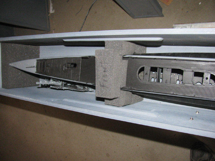
Boat in box with hull hold down foam block.
2 periscopes showing in block.
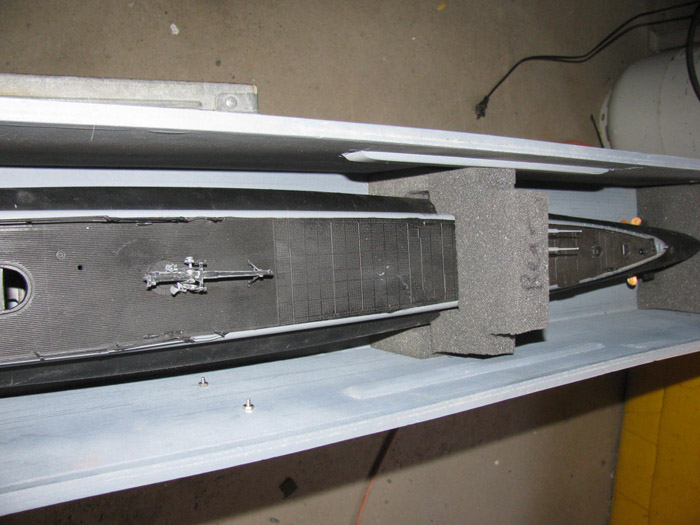
Boat ready to travel.
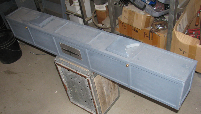
October 15th =================================================
While waiting for parts to be delivered, I put the cylinder equipment
on the bench.
Got the servo extension wires out.
Need to get 2 maybe 3 wires from the rear main electronics tray to
the front electronics tray servos. (bow planes equipment.
The third servo is an option I may put in the boat for fine trimming
of the ballast tank.
Not sure exactly what I will do yet.
One of the things I am waiting for is the brass tube that will go through
the ballast tank.
Here I have a short piece to give me a look at what it will look like.
And I needed to know if the 3 servo wires and 2 power wires will pass
through the tube.
I might be able to use a smaller diameter tube.
I ordered that too.
Other than missing 2 bellow seals, everything is there.
(the C clamp will be removed. It's holding the speed controller in
place while the silicone cures)
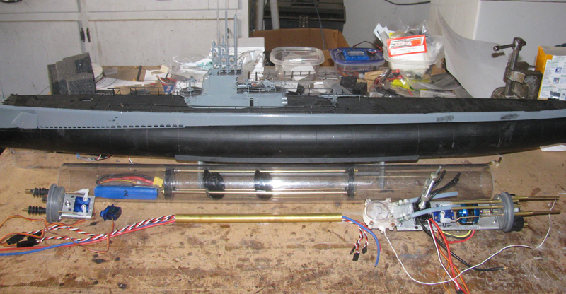
October 16th =================================================
Early this morning I was at the VA eye clinic.
I received a pair of glasses that did not help me.
The left side was clear and sharp but the parallax was so bad that
10 minutes had me looking for a bucket.
The right eye was better but still not clear enough to see and make
out anything.
Saw 2 doctors.
Well, it was all bad news.
Leave things like they are and I will be blind in 1 eye in 3 to 6 months.
The other eye is following along quickly.
The bad news is the fix is surgery.
I am wondering if all the surgeons at the hospital are talking to each
other and taking advantage of me.
Any way it looks like surgery on 1 eye next month.
The right eye which is the worst one.
==================
Got home.
Out in to the shop and I started working on wiring the rear electronics
tray.
Put shrink tube on each wire going through the aluminum tray to reduce
wear on the wires.
Made sure I left room to mount the Pitch COntroller and the Fail Safe.
I have gone as far as I think I can until some of the parts I ordered
Monday start showing up.
I might do some connecting of equipment so this boat can be run on
the surface.
Leave the ballast system unplugged and disconnected.
I would not have to drill holes in the cylinder to do this.
I would have to put temporary ballast lead in the keel but dive trimming
would not have to be done.
Something to think about this week and next.
Next gathering is Oct 26th.
=========================
Quick update:
The ups truck has just delivered the first parts.
These parts are plastic cement and the brass tubing for the ballast
tank.
I can work on the ballast tank.
October 17th =================================================
I got a little time in the shop.
I drilled the ballast tank end caps for the brass tube that the wiring
will go through.
Then I drilled and ground the hole in 1 end cap for the trim system
I am planning to test in this boat.
Lots of hand grinding to get the big hole in the correct place so the
3 bolts that hold the tank together and the brass wiring tube all clear
each other and I can still get to the long bolt nuts.
Got this done.
I was thinking of running this boat as a surface boat at the next gathering.
But I still do not have the rubber boots needed for the rear end cap.
oops.
---------------------------
While in the shop and having the plastic cement, I glued up the sections
to make the end caps for the GW.
Each cap is made up of 3 sections. Total of 7 pieces of 1/16" sheet
plastic.
I make the end caps in 3 sections so I can turn the outside larger section
down to size, then turn down the center sections.
After they are turned to the correct size, I glue them together to
make an end cap with the groove already made.
I find it easier to do this with laminated end caps.
If the end cap was a one piece PVC piece, I would turn the cap and
then cut the groove in last.
This take a little more effort to get the groove the correct depth.
SO far this is what I got done late this morning.
I have other things I am doing non boat related.
October 18th =================================================
Turned the plastic parts to make the ballast tank end caps.
4 large disks and 2 smaller diameter disks.
The 4 disks are made from 2 layers of 1/16" plastic sheet.
The 2 center disks are made from 3 layers of plastic sheet.
I turn them all down to the large size to fit the cylinder inside.
Then I remove the 4 large disks and continue turning the 2 disks down
to the size needed to put the o-ring on.
Once the parts are turns, I then put disks on a 1/4" rod. Large small
large disks.
This will make up 1 end cap.
I brushed on the cement bonder and clamp the parts together with the
1/4" rod still through the center hole.
Do the other one.
Let sit over night.
====================
I worked on the ballast tank for the Gato.
Drilled 1/2" holes in the two baffles.
Assembled the parts.
End cap, 3 brass rods, other end cap, tighten all 6 nuts on long rods.
Place the 2 baffles on the rods.
The baffles have slotted holes so they can be place on the long rods
without having to slip over rods.
Make sure everything is straight and slips in to the cylinder easily.
Set the unit on the bench and block it so it does not move.
Use silicone to fix the 2 baffles in place.
Slip the long 1/2" brass tube and put silicone on the ends to bond
to end caps.
This tube is so wires can past from rear tray to front tray. (3 servo
wires and main power leads)
Leave set over night.
This is what I got done this morning.
October 19th =================================================
Had a few minutes and out to the shop I went.
I did the final fitting of the o-ring on the new ballast end caps for
the GW.
15 minutes and it was done.
----------------
Checked the Gato ballast tank frames.
Needed a bit more glue work to hold the middle anti slosh frames in
place.
Went to town and checked if any parts have arrived.
None.
So, I am at a stand still at the moment.
I want the new batteries so I can see if I can cut 1" or so off the
cylinder.
I would like to get more distance from the rear end cap and the propeller
shafts.
I want the dog bone connector to be longer to reduce the angle.
I think I can install the rear electronics tray and equipment to decide
where to drill the ballast tank flood holes.
1 at the rear of the tank and 1 about middle.
I have a large tank at the moment and if I can reduce it's size, I
want to move the front cap back.
I do not want to have a flood hole in the way.
With 1 hole at the rear, I can tip the boat bow up and drain any remaining
water when done for the day.
I plant to start with two 3/8" holes.
If I need more, I will drill the middle hole to 1/2" and see what that
does.
October 20th =================================================
Did some wiring.
I made up the equipment end main power.
This is 2 silicone insulated wires that go from the batteries in the
front compartment to the main plug in the rear.
This plug powers the main motor speed controller and the ballast pump
motor speed controller.
The main motor speed controller supplies power to the Rx to the servos.
I soldered the 3 pump motor wires to the pump speed controller.
I have shrink tubing on the wires but I did not heat them.
If the motor turns the wrong way, I can move the wires to fix that.
NOTE: THinking about the ballast pump and realized, I can finish the
wiring.
Why because it does not matter which way the pump turns.
The inlet and outlet tubes are 3/4" apart from each other and I can
reverse the hoses and do the same thing with out soldering anything.
This is a 10 amp speed controller with forward and reverse.
Size is about 1/2" by 1" and 3/8" thick.
Then I will heat the shrink tubing.
I can not make up the battery end of the main power wires.
Have t wait for batteries to know what ends plugs I need.
Also will I connect them together in parallel or individually.
I checked the brass tube going through the ballast tank for air tightness.
Needed to silicone the inside side just to make sure.
The ballast tank will be open to out side water pressure which is not
much.
Back to real life stuff.
October 21st =================================================
No work done to day.
Had appointments are 3 VA centers.
All went well.
--------------------
More good news.
More parts have arrived.
2 mini 850 mah batteries arrived by UPS.
I also received e-mail message that the other 2 800 mah batteries are
waiting at the post office.
There are still two items yet to come.
Boot seals and a new battery charger.
Both are expected here end of month or first of next.
With the batteries in hand, I can determine the cylinder overall length.
I can cut the cylinder and then I can decide where the ballast tank
will sit.
The ballast tank is ready to slide into the cylinder.
Then I can start the drilling of flood holes in the cylinder.
2 or 3 should do what I want.
This coming Saturday is the SubRonLA scheduled gathering.
I think the Gato will be going for a show and tell.
Actually it will be more to get suggestions from the more experienced
builders.
Their experience is much appreciated.
And they may have ideas that are easier to execute.
October 22nd =================================================
New batteries have arrived.
I needed smaller size batteries.
Will O. suggested these Zippy batteries.
What I got was a 2 batteries pack.
These are 850 mah mini batteries. (LiPo)
So by using 2 batteries in parallel, I get 1700 mah.
More than enough for a day's running. (3 to 4 hours)
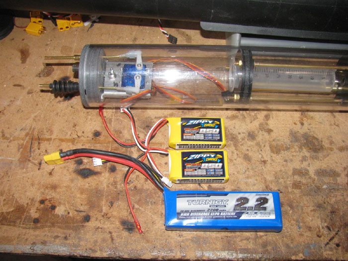
Batteries on thin side
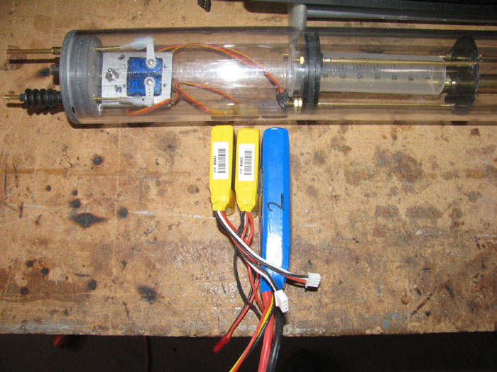
Batteries in cylinder.
(There is room for a mini servo I will use for a trim system. (maybe)
I amy get more room after water trimming.
I may be able to shorten the main ballast tank.
I made it long to start so I would have more positive buoyancy.
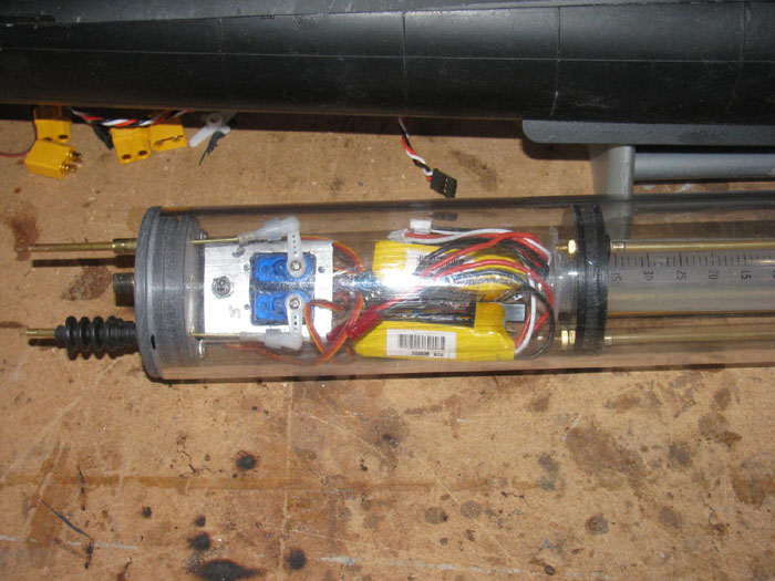
With these batteries I was able to cut off 1.1/8" off the cylinder.
This length was added to the propeller drive shafts.
This made the angle much less strained.
October 23rd =================================================
After doing stuff in town I got in to the shop, I remade the rear control
linkage.
It had to be lengthen by 1/25" to make up for cutting the cylinder.
Got the connectors for the rear control linkage and the front control
linkage.
It all looks good.
I will be away the next couple of days so, I decided to prepare the
boat to go in the transportation box.
Got all the little screws and bolts in to a plastic box so they are
all together in one place.
The boat in the box is now sitting in the living room ready to go to
this Saturday SubRonLA gathering at the lake.
The boat is ready for show and tell.
Only thing not in the cylinder are the 2 servo wires and main power
wires.
I have had them in the cylinder to make sure they fit but not needed
for show and tell as they will block seeing most of what is in the cylinder.
I still have 2 parts coming which are scheduled to arrive in the next
week or two.
They are not coming together so 2 deliveries to come.
Tomorrow, while out, I will pick up more 6mm hose which I need for the
ballast system.
These hoses go from the rear end cap to the conning tower mast and
to the top of the ballast tank.
They are slip connections so putting them in is a matter of seconds
as far as time required.
October 24th =================================================
Back from town.
The big town.
In my going here and there, I picked up the silicone hose needed, the
medium CA and some needed power plug ends.
I think I only need boot seals to arrive.
All is going nicely.
A might slow but udder the circumstances I think it's all good.
November 2nd
There has been no work on any boats while I wait for parts.
This morning at the post office, the last of the parts is here.
However, I may not work on any boats because I have eye surgery coming
up
Don't want anything going wrong.
So I am going to take care for the next couple of weeks.
I will go out to the shop and check the new seals to make sure they
are the correct size.
If not, I will be making adapters.
Or reordering more seals.
This post is to let everyone know I am still here and all is going okay.
November 3rd =================================================
Got a few minutes in the shop.
Good news, the seals fit perfectly.
All seals installed on the Gato electronics trays. (End Caps)
Got a new battery charger.
The one I have uses car battery to charge.
There is a small part in the charger that burns out and gives a charging
error and shuts down.
Research found a video showing the part and how to replace it with
a little larger part.
This would end the error message.
I looked for a 120 ac to 12 volts dc power supply.
Turned out that buying a new charger with 120 ac already included,
was cheaper.
And it is a duel charger so I can charge 2 batteries of different types
at the same time.
After reading the instructions, I found I was missing a line that included
a rule necessary to use the memory.
A 3 second rule.
Hold 3 seconds to by pass the setup and run the charging program.
I now have 4 batteries in memory.
LiFe 9.4 volts (Tx)
LiPo 9.4 volts (Tx)
LiPo 7.4 volts (Gato main power)
NiMH 12 volts (Akula II/Skipjack main power)
Turns out that the new charger charges the batteries much fast using
the same 1 amp charge.
The display says that I am getting a more consistent 1 amp where the
car battery gave a .8 down to .6 amp charge.
I can now charge while working in the shop and not have to stop and
be where I can see my car while charging. (making sure someone doesn't
drive off with the car)
Next 2 weeks I will be dealing with surgeons again.
Not sure how much time in the shop I will get.
November 7th =================================================
5 hours of testing my eyes at the hospital yesterday.
Brought home several medical things to use up by Monday evening so
I will be ready for surgery Tuesday morning.
When I got home yesterday, there was a message asking if anyone was
up for running at the lake this Saturday.
I responded saying I was not sure because at that moment, I could not
see out of one eye and the other was thinking it didn't want to work either.
Got through today and all is back to normal ... almost.
I responded to the message a second time saying I was good to go.
So it looks like boats in the water this Saturday.
November 7th =================================================
While out and about today, I picked up needed power plugs.
I know, I got some 2 weeks ago.
Turns out I did not take in to consideration that I needed to make
up charging cable.
I will most likely make that tomorrow while charging boat batteries.
Think it's time to run my Akula II.
It has been sitting in the living room for some time without getting
to the lake.
Ran my Akula II on Saturday, Nov 9th
Was a very good day.
Did have issues at first because the rear planes where reversed.
A quick plug flip in the tX and all was good.
Now this became a mental problem.
I run 2 boats on the same Tx.
This is not a computer Tx so any and all adjustments have to be made
in the boat.
By reversing the Akula II, the Skipjack is not backwards.
I bought servo reverses some time back and in fact there is one on
the rudder in the Skipjack.
After looking for those little ... items . I found none.
Looked for them online and found every where is out of stock.
Well, this will not do.
So I looked up reversing servos mechanically.
Found a video on how to do it and to the servos I use.
It was a ten minute job.
It required opening the servo case and moving 2 pairs of wires.
2 to the motor and 2 to the potentiometer.
Reassemble parts.
Test.
Good to reinstall in boat.
Now the fun part.
While looking for the little buggers, I found my work sheet for building
the Skipjack electronics tray.
And right there on line 7, "Reverse channel 3 in TX".
Now in the future if I want to fix this issue so I do not have to modify
the servo, I can move the rudder to the planes servo location and the planes
servo to the rudder location.
This would do the same thing as reversing the servo.
Or I can just keep watching to see if the Servo reverses become available
again.
They are about $3.50 each.
=================
Now for an update...
Tomorrow is eye surgery day.
I am ready.
November 17th =================================================
How about a real update.
I still have not decided on a ballast system for the Gato.
But I can do some wiring.
So this morning, out in to the shop I went.
I have all the parts now so I put them on the bench next to the cylinder.
Making sure I have room for everything.
With the new smaller size batteries, I have more room than needed.
(maybe)
I decided to hook every thing up one part at a time.
All these parts are not in cylinder or boat.
1. I found a battery with the correct plug to hook to my electronics
tray.
I will be feeding the Rx through the Main motor speed controller.
My other boats are done this way.
Enough voltage to run the main motor and the speed controller reduces
the voltage for the Rx.
Plugged the main motor speed controller in to the Rx.
The main motor is hard wired in to the system.
Turn on Tx and then Rx.
I have forward and reverse.
Turn off Rx & Tx.
2. Plugged in the Rudder servo.
Turn on Tx & Rx.
I have main motor and rudder control.
Turn off Rx & Tx.
3. Plugged in the rear planes.
Turn on Tx & Rx.
I have main motor, rudder and rear planes control.
Turn off Rx & Tx.
4. Plugged in Bow planes retract servo.
Turned on Tx & Rx.
I have main motor, rudder, rear planes and retract servo.
Turn off Rx & Tx.
5. Plugged in Bow planes pitch servo.
Turned on Tx & Rx.
I have control of Main motor, rudder, rear planes, retract servo and
bow plane pitch servo.
Turn off Rx Tx.
6. Plugged in Servo that may be for trim control. (at this point it
is an option being thought about)
Turned on Tx & Rx.
I have control of main motor, rudder, rear planes, bow retract, bow
pitch control servo and trim servo.
Turn off Rx.
7. Plugged in Ballast pump.
Turned on Tx & Rx.
Well it appears I have control of the ballast pump but it also looks
like I have a motor that has problems or a speed controller that is about
to burn out.
(I will have to check in to those parts)
But I have control of the main motor, rudder, rear planes, bow retract
servo, bow plane pitch servo, trim servo and ballast pump.
That is 7 items controlled by the radio.
The count is correct.
All items work correctly expect the ballast pump motor/ speed controller.
I do have new parts I can replace the old parts with.
Keep in mind that the ballast system parts ran in my Skipjack for 2
years before the Skipjack was modified to a piston system.
I really need to decide on the ballast system.
Use this roller pump or something else.
I have to run the 2 main power wires through the ballast tank as well
as 3 sets of servo wires.
I have a 7/16" brass tube going through the ballast tank that works.
I can get the servo plugs through it, one at a time.
I have long extension wires that I need to use to access the plugs when
removing either the front or rear electronics trays.
This is what is holding up the ballast system.
The pump motor is an out runner motor and the wires may touch the spinning
housing.
If I go with air pumps, this will not be a problem.
With air, I need to build a valve to direct the air from inside to
outside intake.
Got to find the photo of one of these valves and see if I can build
it.
============
I am still going t the hospital once and some times twice a week.
The big stuff is over for now.
Surgery on my eyes is now on hold for other things to get done.
I have more surgery on my left ear but that too has to wait until my
neck surgery has healed more.
I am trying to get scheduled to get new glasses .. where this all started.
I have an appointment but it is so far out that I am trying to get
in on a cancellation.
I have done this for other things so I will see how it goes.
As far as my health.
It is good so they tell me.
November 18th =================================================
Got out the needed tools and proceeded to remove and replace the ballast
pump motor and while I was at it, I replaced the speed controller.
20 minutes later this is done and tested.
But before I started, I looked at the Tx because it was originally used
for the Skipjack which had some of the settings down as low as 50% on the
two speed controllers.
Set all settings to 100%. Had 1 channel set to 130%. Interesting.
After replacing the ballast pump motor and speed controller, I testing
all the channels again.
The main motor was too fast.
Went in to the Tx menu and reduced the forward and reverse to 50%.
A good starting point that can be changed once I have the boat in the
water.
I don't want the motor over speeding to start testing.
----------------
I have made a decision on the ballast system.
I am going to trim the boat, Positive.
When the ballast tank is completely full of water, I will set the conning
tower top at the water surface.
From there I can fine adjust it with weight and foam as needed.
By trimming the boat here it will give me the size of the ballast tank.
I made it bigger than needed because I did not know what the volume
should be.
Easier to make smaller than bigger.
I will also set the waterline about 1/4" high.
Then I can weigh the boat down to it.
This should give me plenty of ballast tank to add the trim tank later
if I find I want to have the boat as a negative boat.
I might have this ready for it's first run at SubRonLA gathering scheduled
for Dec 14th.
If not, I have 2 other boats ready to go.
--------
Tomorrow it is off to the doctor again.
This is the primary doctor and not the surgeons.
This doctor is trying to get my BP under control.
This I have learned is why the eye surgery was canceled.
The low number was too high.
Have to get it down if eye surgery is to happen.
Nov 20th =================================================
I have been thinking. (trouble to follow ... usually)
I had a few minutes in the shop this morning.
I installed and tested the pitch controller.
Next, I started to install the Fail Safe.
As I was getting ready to do this, it occurred to me, that it would
do nothing to save my boat.
At this point the the ballast system has no way of making the boat
positive to come up.
The boat will need t be trimmed with about 1/2" or more of the conning
tower above the water surface.
The ballast system is an air system.
The pump brings air down the mast through the pump in to the ballast
tank to surface. or rise to water line.
To submerge the pump is reversed and pumps the air out of the top of
the ballast tank and out the mast.
If the boat submerges enough to get the mast under water, there is
no way to get air to bring the boat back up.
This is what the trim tank I was thinking about was to do.
Bring the boat up high enough to get the mast out of the water for
air.
So, it looks like I am back to building some sort of trim tank that
will tim the boat negative and positive to get the mast to the surface.
I will have to do some testing to see if I have servo strong enough
to move a syringe piston or make a diaphragm to do this.
But for now, the next couple of day, life is getting in the way.
I was hoping to get the boat in the water for trimming this weekend.
Still might get there.
But if I want a fail safe in my boat, I have to come up with a way to
make the boat positive after submerging.
Or I will have to make this a dynamic diver in stead of a static diver.
I have flipped the coin and I am just waiting for it to come down and
tell me what I am going to do.
=====================
Afternoon update:
Went out to the shop and I got nothing done because it was too cold.
Temperature in the shop was 53 degrees and falling.
Yea .... I am getting too old to work in the cold.
November 22nd =================================================
Scott,
This is certainly an option.
Dropping ballast weight has been used for a very long time.
It is a consideration.
Because of the ballast system I have in the boat at this time, (it may
change as I go), it only works as long as I keep the air intake mast above
the surface.
Should the boat go below the surface and take on water in the air hose,
the boat will become negative.
How much remains to be seen.
If it is becomes too much I may not be able to drive the boat back
to the surface to get air.
I could use a high pressure emergency air tank but it is not my first
choice.
I will trim the boat positive and keep up to an inch of the conning
tower above the surface when the boat is not moving. (dynamic diver)
But I like boats that can be ballasted down to slightly negative and
then be able to trim the ballast to bring it back up.
But the system in the boat now will not do this.
It needs a secondary ballast system to take the boat from positive
to negative and back again.
I have some parts on the bench that should do this, if I have a servo
strong enough to operate the piston/bellows under water pressure.
I can also use a small motor to move the piston/bellows but I need to
make electrical stops so it does not over run it's limits and sink the
boat when uncontrolled water is let in to the cylinder.
So first I will finish the electronics so the boat is positive.
I will water trim the boat to get surface waterline and then see how
much ballast it takes to get to the top of the conning tower.
This will show me how much ballast I need to get to negative.
Shouldn't be much.
Then I can raise more of the conning tower out of the water and make
the secondary ballast system more.
This should give me more trimming ability and the necessary positive
ballast to bring the boat up to get the mast out of the water to finish
the surfacing.
It all sounds complicated but it not.
The secondary ballast system is a simple small piston to create positive
rise.
I would like to get from 4' down to periscope depth which is where
my air intake is.
The main ballast tank is only open on the bottom with 2 small 1/2"
holes.
The air is introduced in to the ballast tank from the bottom with a
brass tube that goes to the inside top of the tank.
When diving the boat, the pump sucks the air out of the top of the
tank until water fills the tank and water is pumped out the mast.
The secondary system changes the size of the main ballast tank with
a small piston/bellows.
I have been researching small servos with high torque.
I sound 3 that have over 45 ounces of torque.
So I will do some testing on the bench to see if that is enough to move
my piston/bellows before I order a new servo.
I hope is to start water testing this weekend.
Until I know how much ballast water I need, I am sort of stalled on
the build.
Water testing will also show me how much lead ballast I need.
I can make up ballast weights ready for installation.
I will need to make molds for these weights.
My other molds are a bit too big.
November 23rd =================================================
Out in the shop, I looked for ballast weights.
I make 38" thick by 2.5" wide and several inches long so I can cut
what I need.
I found 2 large weights.
Also gathered up so loose lead to melt down and make more weights.
I fit the 2 blocks in the Gato and found the large one was too thick
and the cylinder would touch it and hold the cylinder up a little.
Took it out to the all steel work bench and hammered it down until
it was about 1/4" thick.
Then I put the block between the vise jaws and hammer a curve in to
it.
A few test fits and I now have it fitting inside the hull curve. and
the cylinder does not touch any more.
Here the 2 blocks are shaped and the newly pour block in the 2" aluminum
channel, poured to about 1/4" thick.

Here the 2 blocks are in the bottom of the hull, not installed.
Just sitting.
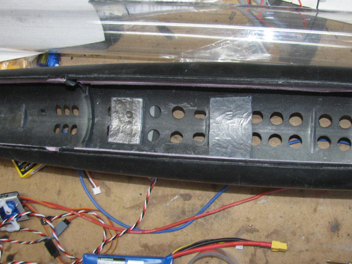
The lead bar is still sitting on the work bench so it will cool completely
before I start cutting it in to smaller blocks.
I have no idea how much weight I need.
This will be trial and error once I get the boat in the water.
November 26th =================================================
Having put this off for several months, it is time to drill the ballast
tank flood holes.
I believe 3 holes 1/2" in diameter will be plenty to handle the volume
from the pump.
The pump has 1/8" inlet/outlet tubes.
After drilling I cleaned up the outside and inside burs.
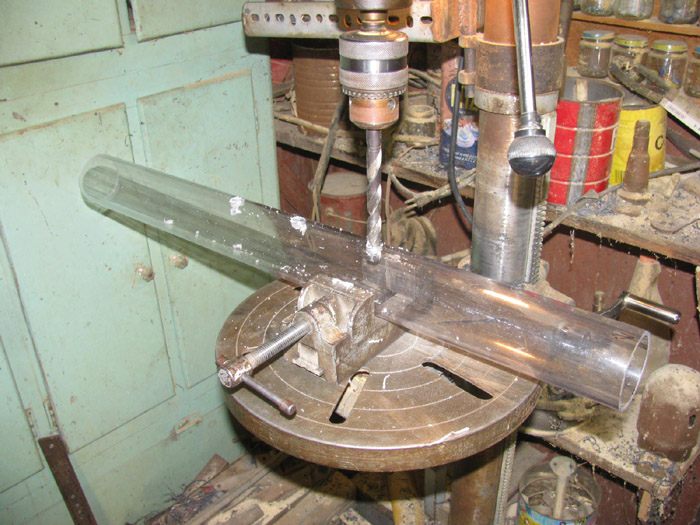
Here the cylinder next to the rear electronics tray and the ballast
tank frames.
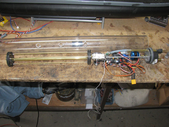
I did some testing of a possible small trim tank.
The servos I have are not strong enough to move the piston in the 1"
syringe.
Thought about using balloons but the ones I have 12" and 15" have been
sitting in the parts box for 10 months.
Out of 9 I found 1 that did not leak.
I am thinking this is not good odds.
So I will not be using balloons.
They seem to hold up if used often.
Like car tires sitting or rolling.
So I am back to setting up as a static diver with equipment and associated
stuff to make it a dynamic dive, later.
November 28th =================================================
No work today.
Just an update.
I have been hearing about rain in Los Angeles and every where down
the hill.
Nothing here until about 6:10 am this morning.
It started very hard then just hard.
Then about 8:30 am, I noticed I could not hear it raining any more.
(I had not opened any windows yet)
About 9:30 am I opened the curtains and to my surprise the rain had
stopped because it was snowing.
Usually when it snows here, it's later in the day.
Late afternoon.
But here it is.
Here are 3 photos from my front porch.
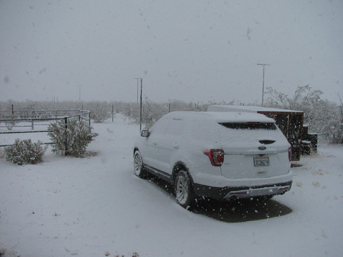
November 29th =================================================
Sun is out.
There is no wind.
It is cold but I think I can cut the lead bar in to ballast blocks.
And I think I can shape them before I get too cold.
Here are all the blocks cut.
I have shaped 4 blocks in the upper row.
The gray blocks are from the Skipjack trimming.
The bottom row are block I cut and have not shaped.
I think I have plenty for the Gato but I made extra just in case.
(while I had the torch out melting lead parts)
Size of blocks.
The mold was 2" wide.
I poured about 3/8" thick and cut about 2.5" long.
They are place in the hull with the 2" width front to back.

The blocks set in the hull.
Each block was tested individually to make sure they were not too tall
and hit the cylinder.
I place each block one at a time where the center gray block is.
Put my short cylinder (24" in the hull and check by rocking the tube
on the 2 saddle frames)
If the cylinder was lifted by the block, I removed it.
Pounded on it with my small hammer over the vise jaws.
This thinned the block and added more curve if it needed it.
I know the blocks cover some of the flood holes.
There are more than enough for the boat to submerge and rise.
It might be slower to get to the water line when first put in the water
and it may drain a little slower when I take it out of the water.
Remember the big holes are 3/4" in diameter +-.
The little holes are about 3/8" in diameter.
None of the blocks are siliconed in place at this time.
I will do that when I put the hull in the water for trimming.
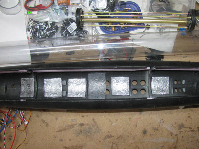
December 2nd =================================================
Out in the shop and still cold. 40 degrees.
So what can I do that will not take long.
Put the cylinder with end caps in the hull.
Place it against the stop blocks.
Measure for the 2 dog bone extensions.
Having cut the nylon dog bones in half some time ago, I put them in
the lengths of brass tube I am using to lengthen the units.
I noticed that the dog bone connectors hit the brass tube when the
ends are all the way in.
I pulled them out far enough to clear the brass tube and connector.
Measured the needed tube and cut.
Over the the other shed where I have some of my bigger tools. With
the length decided , I put the first dog bone unit in the table vise to
hold it then I drilled 1/16" hole to accept the brass rod I will use to
pin the tube to the bog bone ends.
Back to the other shop and using a small ball peen hammer, I peened
over the ends of the brass rod pins/
Here the 2 drive shafts are pinned and ready to be used in the boat.
Note: The bottom dog bone is new. The top is about 6 years old from
my parts box.
The nylon ends
are bigger and do not fit the brass connectors.
I tried
filing the balls smaller but this did not go well.
Option
2. Drill the brass connector 1/32" bigger down the center.
This did the trick allowing the nylon ball to slip in with just a little
clearance.
I checked the other new dog bone unit and found the same issue.
Bow to go get warm.
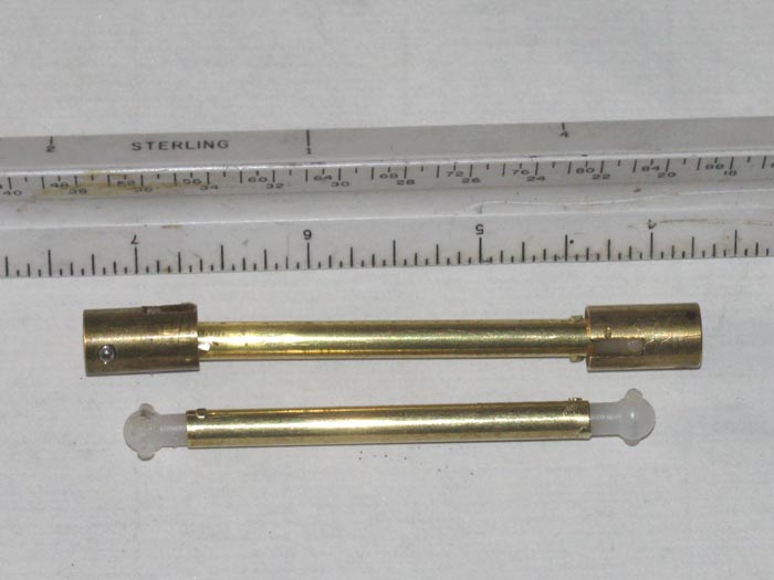
December 5th =================================================
Still cold in the shop.
But I got to try to get my 10 minutes every day working on something.
While I was outside transferring propane from my 60 gallon tank that
lives on my truck in to the house tank, I thought I would go in the shop
and see what I could do.
Took the cylinder out of the hull.
Removed the front electronics tray and then proceeded to remove the
rear electronics tray.
This was not easy.
The tray was wedged in and I had to use considerable force to get it
out.
Looking in to the cylinder to find what was causing the problems, I
could see that the servo wires and power wires where tight against the
cylinder tube.
So, I need to clean up the wiring.
Shorten wires that can be shortened and reroute those I can not cut.
I got the 2 servo wire sets shoved through a length of shrink tube.
I can now fix this to the under side of the tray where it touches nothing
but the tray.
I see I can shorten the 3 ballast pump motor wires.
There appears to be a large loop of wire that is not needed.
I can cut maybe 5" to 6" out.
Then the wires will not be looping from motor to the speed controller.
They will be almost straight with a little extra to flex a bit.
The main power wires plug is currently sitting to the rear.
It needs to be at the front where the power wires extension come from
the front electronics tray through the brass tube going through the ballast
tank.
I will have 3 servo wire sets extensions going through the ballast tank
tube and I will need to make sure I have enough to get the trays out, one
at a time.
The extra wire will be in the front section.
There is more stuff in the rear tray than the front tray.
----------------------
I also see that the rear tray is angled down at the front end.
This is where the ballast tank pump is located.
I can see that the motor shaft is touching the inside cylinder wall.
I can not bend the tray at the end cap because the main motor is lined
up and runs very smoothly.
I can bend the tray just in front of the main motor and behind the
2 servos mounted on the tray.
I only need the end of the tray up about 1/8".
To keep it up when n the cylinder, I have a piece of soft but stiff
foam I plan to mount next to the pump.
This will keep up pressure on the tray and hopefully keep the motor
shaft off the cylinder wall.
It should also allow the tray to slide in easier.
There should be no contact of any equipment on the cylinder wall.
That is what I would like to have.
-------------
I have high torque servos coming.
I will see if they have enough torque to work my small trim tank piston.
If not, back to a positive trim boat.
==============
Now more good weather news.
Another storm it due here tomorrow to Sunday.
No work in the shop.
I might bring the rear tray in to the house and work on it on the kitchen
table.
Or not.
December 7th =================================================
Have time and I have cleaned up the rear electronics tray.
Removed un needed wire length and routed the wires so they do not interfere
with the main motor or ballast pump motor.
This is the rear electronics tray.
It has the
8 channel receiver
Main propeller motor
Propeller speed controller.
Rudder servo
Rear planes servo
Ballast pump/motor
Ballast motor speed controller
Pitch controller
Fail Safe lost signal
Main power wires and distribution
Bottom of tray.
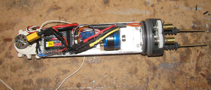
Top of tray.
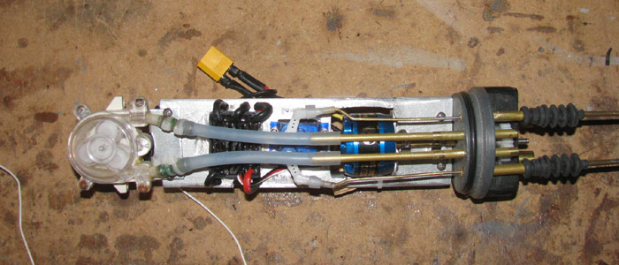
At this point I need to work on getting the tray to go in to the cylinder
smoothly.
The pump motor angle needs to be changed to get the motor shaft off
the cylinder wall.
I am not sure if it is touching.
I need to install it and using a flash light see if there is clearance.
It may have been all the wires that where pushing the tray down making
the motor shaft touch.
Easy enough to check and fix.
January 1st, 2020 =================================================
I do not travel on New Year's day.
It has warmed up outside nicely.
So here it is, the boat's first launch.
This is after setting the boat in the water and doing nothing with
the ballast system.
Bow is at waterline and stern is low.
There are only 3 lead ballast blocks in the hull.
I will remove the after one when I take the boat out of the water.
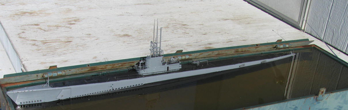
Ballast system set to dive.
Boat is level from back to front.
The water is at the deck side gray at the stern.
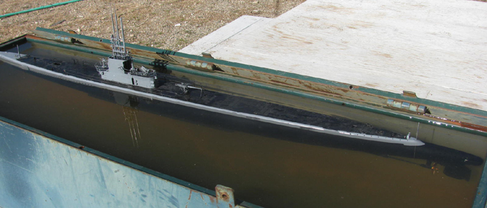
Progress of first dive.
Stern dropped like a rock.
Bow is still up.
Still diving.
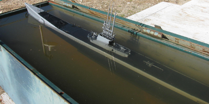
As bow dropped the stern came up.
Boat is almost level here.
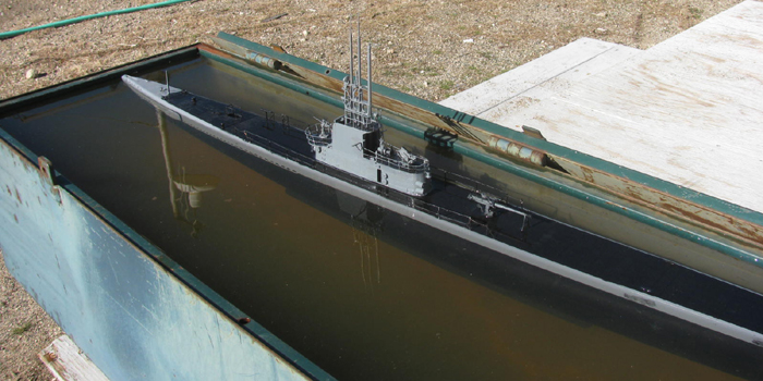
Dive stopped with water at 1/4" from top of conning tower.
This is a little deeper than I want.
I would like 1/2" to 3/4" of conning tower above the water.
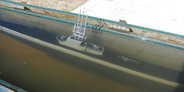
Surfaced the boat.
This is close needing about 1/2" at the stern and 1/4" at the bow.
But until I get the submerged trim correct this means nothing.
I can see that my ballast tank is over sized and I will probably need
to make the tank a little smaller.
But for now I will keep the over positive trim.
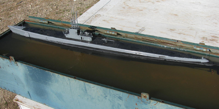
Boat needs weigh removed and moved.
The stern is on the bottom and the bow is under water.
Took the boat out and removed the rear most weight.
Back in to the tank.
The boat dove better and closer to level.
This time I continued the dive.
I want to know the ballast tank is full.
Well there was a point where the boat just went to the bottom and the
ballast tank is not full.
Surfaced the boat.
Well I tried to surface the boat.
The stern came up but the bow stayed on the bottom.
Took the boat out of the water and drained the hull and ballast tank.
Opened the boat to remove the forward weight.
To do this I have to remove the cylinder.
A quick look tells me there is a problem.
There is water (1/2") in the forward compartment.
I have the cylinder out of the hull so I removed the end cap safety
wires.
Removed the end cap.
Dumped the water out.
Removed the rear end cap.
No water but there is moisture coming through the ballast tank through
tube.
Got to dry everything out.
My Tx is beeping so it needs to be charged.
Might as well charge the 2 boat batteries.
So my first sea trials showed me I need to take ballast weight out.
I need to look carefully at the front end cap and find where the water
is coming in from.
Now it may not be the end cap but it might be the ballast tank through
tube is not sealed well enough.
Once the battery is recharged and the cylinder reassembled, I will put
just the cylinder in the water and with my flash light look for the leak(s).
I am going to let this all dry out for a day or two.
Reason is the batteries where in the water and I want to make sure
I get them dry.
January 4th =================================================
I decided to out to the shop and maybe look for the leak(s) in my cylinder.
With charged boat battery and charge Tx off I went.
Once in the shop, I was getting ready to plug the boat battery in to
the system.
A quick look at the cylinder ended this venture.
There is still moisture in the cylinder even though the end caps are
off.
Looking at the front electronics tray, I see moisture on the 2 servos.
Then looking at the rear electronics tray, there is a lot of moisture.
The ballast tank section has standing water.
Not just moisture.
This does not look good.
I unplugged the front and rear electronics from the through cables.
Brought the rear tray in to the house hoping the warmer air will dry
it out.
I did look over the front end cap control rod rubber boots.
I do not see and cracks or broken boots.
I think I will remove the electronics trays from both end caps.
Then I can water test the cylinder without electronics.
I have had several events where my cylinders flooded.
This was while running the boats.
Well I got in the water and did the near shore test dive where the
second dive did not go well.
Twice the flooding was cause by me being distracted and forgetting to
put the Schreader valve cap on before launching.
Both times I was able to run the boat on to the shore for recovery.
Opened the cylinder and pulled the battery out.
Both times after several days of drying (summer time, it was hot and
dry) the electronics survived.
I am hoping that it all recovers this time.
But this is the third flooding and you know what they say about the
third time.
===================
After making sure the electronics is dry, I will disassemble everything
and start from step one.
Test each and every piece of equipment before installing again.
This is after I make sure I have the cylinder water proofed.
Worse case, I have to start over with new electronics parts.
I think I have spare parts for everything but the Futaba Rx.
I have a couple but they are 6 channel and not 8 channel.
I have 1 or 2 synthesized Rx but I do not know if they work and I do
not have instructions for them to program them.
Got them in a trade.
I do have a complete system gathered up but I have a specific project
I want them for.
So, the first trim test went okay.
The second test did not.
This will be almost like starting over.
============================
Back in the shop.
I had made several lead ballast blocks.
Here are the blocks set in the hull.
When I got the boat ready for the water, I removed
3 of the blocks.
Left to right.
1,3 and 6.
I siliconed 2, 4 and 5 in with small drops of silicone for easy removal
or movement.
First in water test showed me I had too much lead ballast.
I removed block 5, leaving 2 and 4.
Second water test told me I still had too much weight.
Today, I removed block 2, leaving only block 4 in the hull.
That block happens to be at the cylinder center.
The right block is still in the hull.
These blocks are heavy.
They are 2"x2.5" x 3/8" thick.
Cleaned all the silicone left from removed blocks.
When I cut 2 small foam blocks that where pushed in to the conning tower
at the gun deck level.
They went beside the periscope masts inside the upper conning tower.
This boat does not have a fail safe in it. (yet)
I need to have the boat positive.
The trim testing showed that once the main deck is under water the
conning tower sinks rather quickly.
I need the tower to be about 3/4" above the water.
That was not happening so I hope with foam in the tower, it will be
easier to trim the conning tower above the surface when the ballast tank
is completely flooded.
No it is a matter of getting the electronics to dry out and work again
before more water testing can happen.
January 18th =================================================
I noticed I have not been here lately.
Well some of that is my many visits to the doctors.
But the rest is because it is still too clod outside for me.
But today, I took the cylinder with the front end cap back out to the
shop.
Was out there because my cloths washer is out there.
While in the shop, I looked over the front end cap o-ring groove.
I took a round rod and wrapped 400 grit wet and dry sand paper wound
the rod.
I hand sanded the bottom of the o-ring groove by turning the end cap
by hand and dragging the rod in the groove.
It appears to be much smoother now than before.
Took me about 10 minutes.
My hands got so cold I could not bend my fingers.
I am done!
Got to get warm again.
But I am counting this as my 10 minutes working on the project.
Weather says 52 degrees.
My shop thermometer says 50 degrees but the light breezes feels much
lower.
The walk from the shop to the house has me getting near the house heater
for a few minutes when I come in.
Tomorrow is suppose to be 5 degrees warmer.
I hope to get the electronics back in the cylinder.
Maybe even get the cylinder in to the water tank for testing.
January 19th =================================================
It has warmed up.
Out to the shop.
I assembled the rear compartment.
Making sure to silicone grease the o-ring.
Basically, I installed the front end cap with the 2 servos mounted
on the cap.
Took it out to the water test tank.
I stood the cylinder up vertically with the front end cap down.
I put the cylinder in the water to the bottom of the tank. (about 12")
I left it there for 3 minutes.
Brought it up to inspect the front compartment.
I did not install the rear end cap so there was no internal pressure
built up to hold the water out if there was a leak.
Sure enough about a teaspoon of water in the compartment.
Removed the end cap and drained the water and then wiping it dry.
I inspected the o-ring groove, the 2 bellow seals and the schreader
valve tub.
Nothing appeared to be the problem.
The o-ring did slip in to the cylinder very easily.
I put 2 layers of teflon tape over the groove and regreased the o-ring
and installed.
I looked the 2 rubber boot seal carefully checking between the folds.
No breaks found.
I twisted the boots on the through cap brass tubes.
Very tight.
But I decided to put tie wraps on to make sure this was not where water
was coming in.
Checked the Schreader valve tube.
Could not find any problems.
Okay, reinstalled the end cap in to the cylinder.
Back out to the test tank.
This time I was prepared to pressurize the cylinder.
Holding the front end cap on with my hand, I added air in to the cylinder.
With the front end cap in the water, I see lots of little air bubbles.
I rotated the cylinder and the air bubbles moved with the cylinder.
There where 3 or 4 places air was coming out.
Because I was at the other end of the cylinder, blowing in to the cylinder,
I could not see the very end where the cap meets the cylinder.
What I could see was the air was not coming from the 2 boots or the
Schreader valve tube.
Conclusion is the cap, o-ring and cylinder connection is not sealing.
Even the two layers of teflon tape was not working.
My thought after several attempts to fix this leak issue is I need to
make another end cap and fix the o-ring groove depth.
Also, I think I want to relocate where the control rods go through
the end cap. Currently, they are too close to the Schreader valve tube
and it was difficult to put on and remove the valve cap.
I would also like the control rods low on the cap to be more in line
with the bow planes horns.
So, my next project is to make a new front end cap.
It will be a day or two before I can do this.
I have another project on the drill press at the moment and I do not
want to remove it because getting it positioned right again would be a
lot of work.
So, I will finish it before making another cap.
===================
Update:
After the end cap dries and I removed the electronics tray from the
cap, I found a very small/thin crack between the o-ring groove and the
front edge of the cal.
It was one of those things I could not see but dragging the point of
a new Exacto blade hooked on it.
The air/water was going through the crack to the bottom of the o-ring
groove and even under the teflon tape.
My thought is the cap crack when it feel from the bench to the floor.
This happened more than once during the build.
I just didn't see the crack.
So today I found the problem.
Now to make a new part and replace the problem part.
December 20th =================================================
Quick note:
I was out in the shop getting a couple of tools needed in the tool
shed for the project in the drill press.
As I was sorting through the tools to get the correct one, I remembered
I had made end caps for the GW rebuild.
On the far end of the work bench I found 2 caps.
But these caps where not caps at all but ballast tank frames.
Put them back on the bench and moved some paper plans and found the
2 end caps.
They were turned to fit the cylinder and the o-ring groove is already
in place.
Picked up the correct o-ring and lubed it up.
Put on the end cap.
Got my short test cylinder piece.
Put the end cap on which required working the o-ring to get it in the
cylinder. (the other one on the Gato cap just slides in with out a lot
of fuss)
With the o-ring in place, I look at the contact line.
Looks good.
Okay, this cap does not have the control rod holes.
The Schreader hole is the center hole that I put a 1/4" bolt through
to turn the part.
Put my finger over this center hole and pressurize the short cylinder.
The end cap did not move, I hear no leaks and no loss of pressure.
Conclusion is, I do not need to make a new end cap. (later for the GW)
I just need to drill for the 2 control rods and install a Schreader
valve tube.
Then there are the shallow holes for mounting the electronics tray
and the 2 holes for the safety cable pins.
I may have this done by Wednesday.
My current drill press project should be finished tomorrow.
January 22nd =================================================
Today, I work on the new end cap.
I needed to make a brass tubing reducer.
From 1/4" down to 1/8".
The 1/4" end is for the rubber boot.
The 1/8" is for the 3/32" tube to slide through.
The 3/32" tube has the 1/16" control rod end solder in to it.
So, I measured and drilled the end cap to get the control rod exits
through the end cap in the correct place.
Also drilled for the Schreader valve going through the end cap.
Dug through my short brass tubing box and found all the pieced to make
2 through end cap bushings.
Cut them to the length I needed.
They all slip together tightly.
Put a piece of packing tape on the inside of the end cap.
This is to push the brass tubing up against and keep the glue from
running out.
One by one, I put Gorilla glue on the brass tubes then slipped them
together while twisting them to get the glue to go all the way through.
I made the tubes flush on the inside of the cap.
The outside can be cut if need be.
Once I had the tubes in the end cap, I had 2 more short pieces of tubing.
This goes on the out side of the tube going tightly through the end
cap.
These pieces will have the rubber boots on them and they will fit tight.
Found an old wheel and tire out back and took the Schreader valve from
it.
Chucked it up in the drill press and cut the rubber away.
Got the end nice and shiny.
Measured the length against the end cap thickness.
Cut about 1/4" off the back side of the valve.
This will fit nicely once the glue dries on the brass tubing and I
can work the valve in to the cap.
I also made 2 new push rods for the bow planes.
I had 1/8" originally and these fit so very tight on the rubber boots,
that I tested and found that 3/32" would do much better and not damage
the rubber boots.
All the parts have been made and most have been installed in the end
cap.
Brought the parts with glue on them inside the house to keep them warm.
Do not want to test glue that may freeze, out in the shop during the
night.
Moving along, even at this snail pace is getting it done.
January 23rd =================================================
Took the end cap out to the shop.
Cut off the excessive glue.
Gorilla glue expands as it cures filling all the little notches and
grooves.
Sanded the end cap surfaces smooth removing the glossy glue surfaces
on the end cap.
Drilled the hole for the Schreader valve a little bigger.
The pilot hole was a little small.
Also, I cut a small recess for the edge on the valve stem to be flush
wit the end cap surface.
Applied the glue and brought back inside to cure.
I test fit the 2 control rods through the brass tubes in the end cap.
1 slides through just fine.
The other seems to have some glue about half way through.
Not a problem.
Will drill the glue out when the all the glue on the cap has cured.
Most likely will require just hand turning a drill bit through.
No work in the shop tomorrow.
Going to hospital to have a lot of stitches removed on my neck.
Not to worry, all is good so far.
January 24th =================================================
Trimmed the glue from the end cap.
Installed the electronics tray with it's 2 servos.
Installed new push rods with nylon clevis.
(New control rods because I decided to go with a smaller brass
tube through the end cap. The rubber boots fit much better)
Old on the left, new on the right.
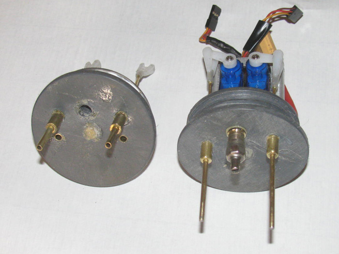
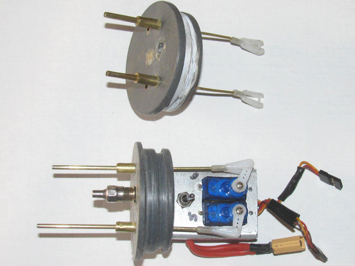
The glue is still soft so the end cap is back in the house to finish
curing.
January 25th =================================================
I have been in town and doing other non boat stuff.
Now in the shop, I have put the 2 sockets in the end cap for the cable
tensioning pins.
I drilled 2 holes for the sockets under the 2 control rod bushings.
These holes do not go all the way through the end cap.
These bushings are not straight with to the end cap.
But slightly angled towards the center of the end cap so when there
is pressure on the pin from the safety cables, the pins will not pull out.
The photos is before the sockets where put in but shows the original
end cap with the sockets.
============================
Looks like once the glue cures on these 2 pin sockets, I can start
reassembling the front electronics tray.
Put the front and rear trays in the cylinder.
Test on the bench while assembling.
Followed by water testing.
If no leaks are found, in to the hull it will go.
Could be a busy day on Monday. I want 2 days on the cure this time.
Oh, wait.
Not monday but Tuesday.
Another doctor visit on Monday.
I got good news yesterday while visiting the surgeon doctors.
The 3 biopsies from a couple of weeks ago came back saying no surgery
needed.
Just an ointment be applied.
This sounds a lot like, I am done with getting cut on.
Very good news.
January 28th =================================================
Finally back in the shop.
Assembled the equipment in to the cylinder.
Did not take long to see I had a problem.
The power wires through the ballast tank have plugs on each end.
The front compartment has plenty of room for all the wires and plugs.
The rear compartment did not.
The power plug wires from the Speed controllers place the plug where
it was beside the ballast pump.
There was not room for both.
I can not move the pump, so I had to figure out how to move the plug.
That did not go well.
Solution end up being, removing the plug and soldering the wires (2
groups of 3) together and covering with shrink tubing.
Now there is room and the electronics tray slides in smoothly.
Cleaned up the o-rings.
Applied silicone grease.
Put he end caps in the cylinder.
Put the safety cables on.
Out to the test tank.
I held the cylinder down 8" in the tank and held it there for about
5 minutes.
I tried looking in the cylinder for water leaks.
Unfortunately, the sun is behind one of my building and the wind is
making the water very choppy.
I could not see in the cylinder.
Took the cylinder out and then pitches the cylinder both ways while
looking in the cylinder, the compartment I had water in last test was dry.
However, the rear compartment had a few drops of water in it.
Okay, in to the shop.
Remove the safety cables. (pull 2 pins)
Pull the end caps out past the o-rings and dumped a little water out.
Only in the rear compartment.
Okay, cylinder now in the house where it is warm and will not be exposed
to the freezing during the night.
Tomorrow with the test tank in the full sun shine and most likely no
wind before noon, I will water test it again and hope to find the leak.
I do not know if it is through the rear cap or through the ballast
tank frame in the middle of the cylinder.
I will find it.
Before water testing, I check all controls with the Tx.
Everything is working just fine.
I even got the 2 bow servos on the correct channels, first time.
More tomorrow after tank testing.
January 29th =================================================
This morning, testing the cylinder continued.
The cylinder was dry from yesterday's testing where a small leak was
visually detected in the rear compartment.
Today, I reassembled the cylinder.
Got my trusty long fuel hose out.
I found a brass tube that would go in to the Schreader valve and seal
with a little pressure by hand.
Put the fuel hose on the other end of the brass tube.
The hose is long enough that I can move to see both ends of the cylinder
while it is submerged in the water tank.
Blowing it to the tube provides a little pressure in the cylinder.
With the cylinder under water, pressure introduced to the cylinder,
I had bubbles on the far end of the cylinder.
Picked up the cylinder and turned it around putting the leaking end
near me.
Back in to the water.
Put pressure in to the cylinder and the bubbles showed themselves again.
To my surprise, the bubbles where not coming from either of the rubber
boot seals or the main propeller shaft seal.
The bubbles where coming from the rudder through cap tube.
It appears the air is getting between the cap material and the brass
tube.
The fix is simple.
I will use Thin CA glue that will run between the brass tube and the
cap material.
I will do this later because the water all needs to dry out in the cap.
I have a rubber hose that has an inside diameter of 3/8".
This will fit over the brass tube without touching.
I will hold the cap so the CA will run down the tube side.
I will put the CA on and then immediately put the hose over it and
blow through it to put pressure on the CA to push it through the gap.
Hopefully this will seal the leak.
Then I can retest to see if there are other leaks.
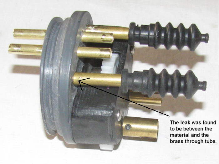
January 30th =================================================
In the shop for a few minutes.
Trimmed the excess glue from the rear end cap.
Cleaned out the control rod through brass tube.
Reinstalled the control rod.
This is all the time I have in the shop today. (most likely)
Will be back at it tomorrow to re assemble the cylinder and do another
in water leak test.
----------------
I have been thinking about the Fail Safe.
I use them on ballast tank systems.
The system I have in this boat if the boat ran below the surface would
not work as the ballast pump would pump water an not air. No help.
Now I think I will put it in the boat front compartment and have it
on the bow planes.
I thought maybe the rear planes but the front seems to make more sense
to me.
The boat is below the surface.
I need it to come back to the surface to get air.
The rear planes could move to bring the boat up but this required the
planes to push the stern down to get an up angle.
This would cause the stern to go deeper before the boat started rising.
Weed issues in the lake I run. Not very deep. Yes I have personal experience
in the weeds.
Then I thought about putting the Fail Safe on the bow plane.
Same below the surface event.
Up input on the bow planes will cause the bow to rise and the stern
with pitch control will try to follow.
The stern would not drop and the bow would immediately start rising.
When the stern drops the mast would also drop, getting them farther
from the surface.
When the bow rises the masts get closer to the surface.
My choice is to have the bow planes on the Fail Safe so the bow and
masts rise quicker towards the surface.
Of course my plan is to never need the Fail Safe to operate.
Besides, I have more free space in the front compartment than the rear
compartment.
January 31st =================================================
Made out to the shop this afternoon.
Reassembled the cylinder.
Included the Fail Safe.
Tested it and it work as it is suppose to.
Prepped the cylinder and out to the test water tank.
Pressurized the cylinder and saw 1 little leak.
Careful examination found the leak to be air from the ballast pump.
The pressure in the cylinder was squeezing the fuel tubing enough to
get a few small bubbles.
After 10 minutes, lifted the cylinder out of the tank and held it up
to look through the cylinder for water in the front and rear compartments.
None except for the moisture from me blowing in the cylinder to pressurize
it.
In to the shop.
Dried everything off.
Installed the cylinder in the hull.
Check all controls.
Made sure to put the Schreader valve cap on. (yea, I have forgotten
before)
Hooked up the fuel air hoses to the cylinder and the conning tower mast.
Out to the tank.
Put the boat in and I have a healing issue.
To be fixes as I go through trimming.
Dive the boat.
Boat slowly starts down.
The boat rolled up right as it went.
Boat got down to the top of the life lines and stop going down.
I keep the ballast pump running.
It was not long when I knew the ballast tank was full of water.
See, the system is setup so when the pump has removed all the air it
pumps water.
Water sprays out the top of the antenna mast like a sprinkler.
Okay, down t the top of the life lines.
Not enough.
I want half the conning tower submerged.
Brought the boat to surface water line.
Dive the boat again with a ballast weight on the for deck.
Dive goes well.
But the dive stopped right at the top of the life lines again. ? ?:
Decided to take the boat out of the water and check a couple of things.
At this moment, I realized my problem.
Since I filled the water tank, the water level has gone down from wind
and evaporation.
The boat has been diving and setting on the bottom of the tank.
Yea, there is no way to trim the boat sitting on the bottom down to
the life lines.
Take the boat out of the water.
Dry the hull and in to the shop.
Open it up to turn of the power.
Remove the cylinder and dry it off.
Turn of Tx.
At this point I will put the weight I was testing the boat with in the
hull.
The silicone needs to cure before I continue trimming.
Put the weight in.
Out the water tank and pulled the tape off that was sealing one of the
4 bottom bolt holes.
Drain the tank.
Why? Well the water has so much dust, bugs and rust in it, that once
I stirred up the water, I could not see down 3" which is why I missed the
boat sitting on the bottom.
Rinsed out the tank and refilled with clean water.
Tomorrow, I will continue water trimming the boat.
The boat is very close.
I just need to find submerged trim with about 1" of the conning tower
above the surface.
Then I will worry about the surface trim.
I should be able to get this done over the weekend.
At least I am going to do my best.
==================
I need a couple hours this coming week to work on my Akula II.
There is nothing wrong with the boat.
I want to try a little modification that might, should keep the boat
turn a bit better.
On one of the other boards, I read about a lower modification that
helped.
I can make this in about 20 minutes and I plan to make it detachable
so I can remove it when the boat is on the bench at the lake and install
it just as I place the boat in the water.
Once in the water no one will see it.
That's the plan, anyway.
------------
Also need to charge up the Skipjack.
8 days from now is one of our groups scheduled gatherings at the lake.
I want to take 2 boats.
Skipjack and one of the others.
February 1st =================================================
Time to do some more trimming.
Filled the tank with clean water.
Prepped the boat and out to the tank it goes.
Start by running the ballast pump to empty the water from the ballast
tank to see what I have for surface trim.
It's okay but light in the bow.
Now, run the pump to fully flood the ballast tank.
When water squirts out the top of the mast I know the ballast tank
if empty of air.
The boat sits too high at both the bow and stern.
I happen to have several different size weights in my pocket.
I started by placing a 1"x1.5"x 3/8" block just in from of the conning
tower and touching the tower for a placement reference.
Bow goes down a stops before touching the bottom of the tank.
Stern is high.
I try a 200 gr weight at the muzzle of the 4" gun. (my gun is on the
stern deck)
Stern drops.
The boat settles with the bow point right at the surface of the water
and the stern down about 2" to 3".
Remove 200 gr weight.
Boat settle in as before with bow down and stern up.
Okay, I ow place a 125 gr weight after of the 4" gun touching the muzzle.
This is looking much better.
Stern is a little high but the bow is about where I would like to have
it.
Took the boat out of the water to check for water in the cylinder.
Okay so far.
At this time I dried the inside of the hull where I wanted the large
weight.
Having on the deck was causing the boat to roll about 15 degrees when
surfaced.
Weights would slide off.
Put the cylinder back in and close up the hull.
Back out to the tank.
In the water, and fill ballast tank with air.
Waterline still is close.
Remove the air out of the tank.
Water squirts out the mast head.
Let the boat set in after shaking the bubble from under the deck.
This is very nice. but the stern is high.
I move the 125 gr weigh back away from the 4" gun about 1".
Let the boat settle.
Too much but it isn't a lot.
Moved the weight to 3/4" back of the 4" gun.
Now I have something to write about.
I wanted half the conning tower submerged when the ballast tank was
completely flood.
The water squirting out the mast head tells me it is full.
Now to fine tune it.
At the bow and stern are flag staffs.
The are about 1.25" tall.
Just happens from one staff to the other's top is half away up the
conning tower.
So I moved the small 125 gr weigh back and forth in 1/4" increments.
I got the 2 staffs to sit with a little less than 1/4" out of the water
at both end of the boat.
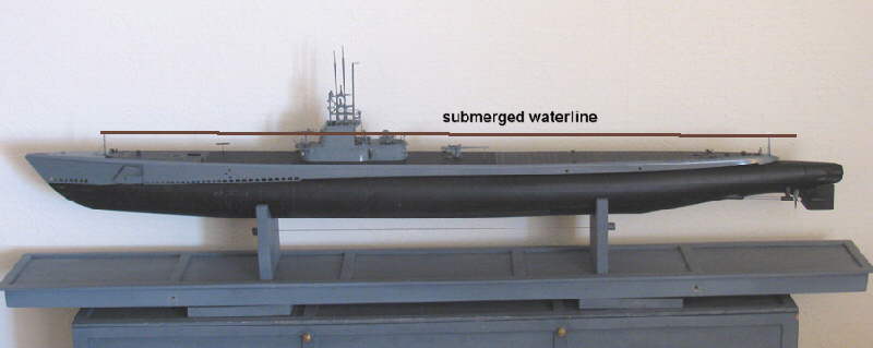
There is a safety back up at this point.
In the conning tower, I place 2 small block of foam.
This will make getting the top of the tower to submerge a bit of work.
The boat is positively buoyant here.
The bottom of the foam blocks are just in the water with this trim
setup.
I can easily push the boat under with my fingers.
So, I imagine that the bow planes should get the boat under with a
little forward motion, thought I would like to not go more than periscope
depth.
I am not going to mount the 125 gr weight. I will leave it loose so
I can move it around at the lake when I get there.
Could be the boat doesn't needed it there.
I have now got a solution for trimming the boat.
Only issue is, after 45 minutes, I have abut 1/2 a tea spoon of water
combined in the from and rear compartment.
So, I still need to work on find and repairing the cylinder leaks.
Then I can work on fixing my Surfaced center of gravity.
This may require more lead weigh and more foam.
But I can choose a weight then make a foam block that will zero the
weight in the water so my current trim will be close.
Now I know why other builders add the brass bar under the keel.
I am thinking, it's not too late to do that.
Finding the brass bar would be the most difficult.
Thought I could get out in the tool shed and make a wood form and pour
a lead long keel bar.
Actually, that sound the simplest to me.
Tomorrow's project. Lead keel weight.
February 2nd =================================================
The photo below is from when the ballast tank spreader bars where made.
What I did this morning was move the brass washer and the tubing sleeve
towards the end of the rod about 1/8".
This moves the frame piece and I left enough room for another piece
of 1/16" sheet plastic.
The sheet plastic has been cemented to the outside of the frame.
(in the vise while they cure)
There is just enough bolt sticking out to get the nuts started and
then I can tighten them up squeezing the o-ring on the inside.
Why the sheet plastic?
To get move ballast tank volume, I remove most of the center of the
frame.
Leaving ears for the 3 bolts and an ear for the brass through tube.
This got me another 3/4 ounce of water volume.
So all in all, I moved the frames a full 1/4" plus wider and got 3/4
ounce in the frame centers.
Oh, I found a leak.
It was one of the frame o-rings.
As I thought they were dry. (with no silicone grease applied)
The keel weights will happen tomorrow, maybe.
February 3rd =================================================
I have to go in to town this morning but I was able to get out to the
shop to check the gluing of the end caps.
Removed them from the clamps.
Look good so far.
Trimmed the plastic sheet that was larger than the caps, with scissors.
Will grind the edges smooth later today.
Took the end caps in to the tool shed.
Drill the six 1/8" holes for the brass spreader bars.
Drill the two large holes for the brass through tubes.
Test fit the spreader bars. GOOD.
Test fit the brass through tube.
Well there's the issue I thought might come up.
The 12" long tube is short abut 3/8".
It fits in the end caps but does not go all the way through which is
needed for good sealing.
Okay. Dig through the brass parts box.
Found a brass tube that slips very tightly over the through tube.
Plan..... I will cut 2 short pieces and slip one piece over each end
to get the length I want.
Then I will solder them on.
That is what I got done in the 20 minutes I had before leaving.
Note: Walked past the test tank and noticed ice.
I broke the ice to find it is 1/4" plus thick.
Tonight is suppose to be colder, longer.
Sure hope it warms up tomorrow.
----------------------------------
More to report.
Cleaned up the two large holes for the brass through tube.
Turns out, I only needed to expend one end about 5/8" to make it work.
Soldered the piece on to the long tube.
Checked for air tightness. GOOD.
Started by cleaning all the spreader rod ends. (threads)
Cleaned the six small o-rings.
Applied silicone grease to o-rings and spreader end washers.
Put o-rings on.
Put the first end frame on then nuts.
Tightened snugly to compress o-rings slightly.
Put second frame on, then nuts.
Tightened snugly.
Made sure the frames and spreader rods where straight by slipping in
to my test cylinder. (short at about 19".
Next I slipped the larger through tube through the frames. to get the
length.
Cut, removed burs and soldered the two through tube pieces together.
Here is the ballast tank frames and spreader rods.
You can see the recesses on the inside of both frames.
This is the extra volume I wanted.
Plus the spreader rods also gave me 1/4" more distance between the
frames.
Ready to put o-rings on and slide back in to the cylinder.
(the frames with o-rings are very tight in the cylinder. Requires
a lot of effort. They don't just slide in)
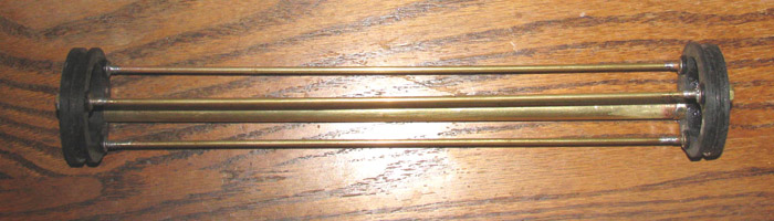
February 17th =================================================
I had a few minutes.
Out to the shop I went.
What to do.
Saw the plastic tree with the clear parts on it.
Okay, these parts are very small.
I started by putting the rear facing search light lens in.
On to the running lights.
Right and left side of conning tower.
A stern light
A light up on the front of the forward mast.
A light on the front flag staff.
Wait.
I do not have enough lights.
Why is that?
It is because I drop 3 of these little (*&^$$) lens on the floor
never to be seen again.
In fact for the mast light, I cut a piece from the plastic tree and
made a light.
There are other smaller yet parts on the tree but I can not see where
they go. Looked all over the instruction booklet.
So, I don't know where they go, I will not miss them.
I got my more than 10 minutes work in today.
A day I didn't think I would be able to get in to the shop.
A good day.
===================
This shows the 2 lights on the rear edge of the conning tower.
Should be green and red.
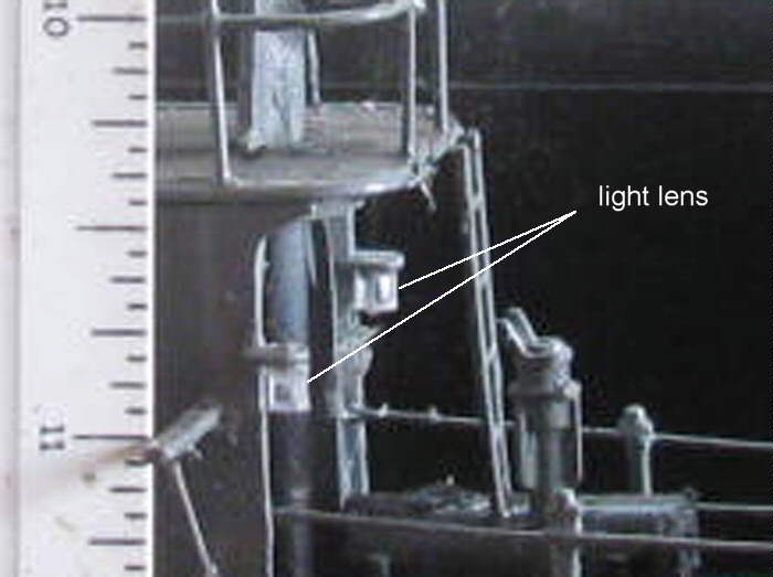
Not only did I clean the tank, I took a palm sander to it.
This made the cleanup go very quickly.
Why the sander.
I had planned to completely sand down the tank/safe after trimming
this boat and repaint it back to looking new.
Even though I built it over 20 years ago.
This safe was built to fit in the back of my little truck to take customer
ammunition to the various ranges on weekends.
It also fit in my Jeep Laredo.
I made it to carry ammunition but I had to get my competition guns
in it when I travels to 3 and 4 day matches.
The safe ended up being 54" long so my 1874 Sharps with a 32" barrel.
Served me well for more than 20 years.
Then I realized, the Gato was too long for the bath tub but the safe
would do nicely.
So this is where I am today, using it to trim my boat.
February 19th =================================================
The water tank/safe was dry this morning.
I wipes the area around the 4 bolt holes and place tape over the holes.
Added water.
Prepared the cylinder for water testing.
Looked at the end caps to make sure the o-rings had their fine black
line of contact all the way around.
Looked through the cylinder wall to check again the ballast tank frames
o-ring contact. (still looks good)
Put together the fuel hose with a brass tubing tip that will be inserted
in to the schreader valve so I can pressurize the cylinder once in the
water.
All is ready.
Out to the water tank.
Placed the cylinder in the tank stern section first.
Watching for bubbles. None.
Pushed the rest of the cylinder under the surface watching for bubbles.
I hold the fuel hose in my mouth while doing this and I keep pressure
on the brass tube stuck in the Schreader valve.
Okay, now it's time to blow lightly in to the fuel hose.
This puts positive pressure in the cylinder.
Still no bubbles.
I did this for bout five minutes.
So far everything is good.
Take the cylinder out of the water and wipe dry for now.
Got a few things to do this morning.
I think I will get to water testing the boat before long. (today)
This will be to trim the boat and get the ballast lead weights right.
Find the correct weight and location for each ballast block.
Two weeks ago, I had it so close.
But having the surface and submerged center of gravity (s) merge and
roll the boat of 10 or so degrees was not acceptable.
More to come.
============================
Here is the more....
First test.
Boat in the water with ballast tank full of air.
Looking tells me the boat is too low in the water at the stern by 1"
or so.
Down on the bow by 1/2" or so.
The fix is to remove some ballast weight at this point.
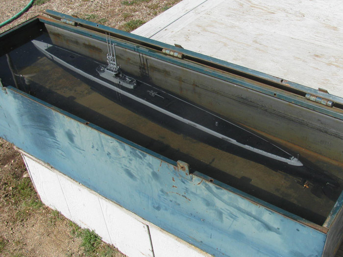
Before removing from the water and removing weight, I need to check
the full dive trim.
Started up the ballast pump and watch the boat slowly dive.
Don't panics, I can reach the bottom of the tank!
Boat dropped down to the bottom.
So removing some weight will help this.
Removed the boat and opened it up.
Took 1 lead ballast block out and move another towards the center of
the hull.
Back in the water.
It is getting closer but still too much ballast weight.
Opened the boat and took a middle weight out.
Off to the tool shed I went.
Put the block in the band saw and cut 1/4" off the block.
(note: I have been using lead bullets at 200 gr and 125 g.
This way I can fine turn the trim for weight and fore and aft pitch
when submerged.
Put the boat back together with the cut ballast block and moved it forward
this time.
Back in the water.
Still too low in the water.
Maybe cut a block in half this time.
Each cut is a different length so I can pick and choose various sizes
during trimming.
Put the blocks in and back to the water.
Oh so very close.
Still too low at the stern but maybe a foam block will fix that.
But before I do that, the old problem with healing during the static
dive and again during the surfacing.
The boat rolls over about 5 to 10 degrees.
I need to get the ballast weight lower.
Problem is, the blocks are at the bottom of the hull across the keel
line.
I think I will have to consider finding a long brass square rod and
mount it outside the hull on the keel.
Others did this and I did not see them having this issue.
Maybe, I can make a long square rod out of lead.
I will have to think about this.
Besides, there is nowhere close to go get this brass square rod.
I would have to order it.
I can make a mold on top of my steel work bench and pour my own.
That will probably be my next project.
The Gato will not run like it is even though I have it trimmed very
close.
====================
I thought I would show everyone how I did this ballast system.
I am using a roller pump which will pump water or air.
I am using it to pump air.
On the surface and to fill the ballast tank with air, the pump draws
air through a mast on the conning tower.
Now to dive, the pump draws air from the top of the ballast tank and
expels the air through that same mast on the conning tower.
When the ballast tank is empty of air, it will start pumping water.
The water will spray out the top of the mast giving me a visual that
the ballast and is empty of air or full of water.
I wanted a way to know so the boat would not get negatively heavy.
I took a photo of the water starting to spray out the mast.
If I had waited a second or two more, it looks like a yard sprinkler.
The photo shows the boat is still a little deep in the water for this
system.
I want about 1/2" of the conning tower above the surface.
With the boat submerges there is about 4" under the keel to the bottom
of the tank/safe.
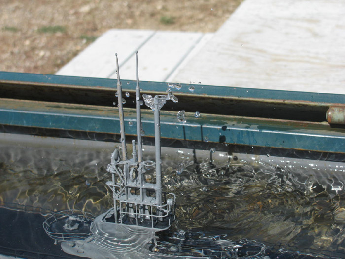
There will be no boat work tomorrow.
Maybe an hour or so Friday.
But I have made up my mine the boat will not be ready to go by this
Saturday.
I will take other boats.
Also depends on what is done at the VA tomorrow and weather says it
might rain that day.
Won't know until the day gets closer.
======================
Another issue:
After more than an hour in the water I have a small water leak in the
rear compartment.
There was about a tea spoon of water.
I will find it and get it fixed.
February 20th =================================================
Today went well at the hospital.
Got in to the shop to look and see if I could put some ballast weight
under the keel.
Decided it was a no!
I then did a small test with a short piece of cylinder and a couple
of small weights.
What I did was place 2 weights side by side touching in to the cylinder
piece.
I rolled the cylinder over about 10 degrees and let it go.
I watched it right itself.
Then I moved the weights a part by 1/2".
taped them in place so they wouldn't slide.
Rolled the cylinder piece over 10 degrees and let it go.
Watched it right itself.
The second test showed the cylinder rights itself faster and stopped
rocking quicker.
1 weight moves to the center line of the cylinder basically having
no effect on the cylinder roll.
The other weight move higher up the side of the cylinder putting mover
effort to pull the cylinder on that side down.
From this I went out to the tool shed and cut one of my extra ballast
blocks in to 3 pieces.
I have a space near the center for the hull where I can place these
2 blocks with a 5/8" space between them making both go up the sides father.
I have also been talking with Tom about the mini air pumps.
I wanted to know if they pumped water as well as air.
He said they are bio directional but I do not need this for what I
plan to do.
Air in with pump and air out with vent valve.
2 pumps are smaller and weigh less than the roller pump.
And even more important, I can get the pumps lower in the cylinder
moving CG a little lower.
I have always thought at some point I would replace the roller pump.
To today I think I will make that change while I am still in the trimming
process.
Why put the effort in to final trimming and then have to do it all
over again later.
Going to do it now.
Will order the air pumps next week.
February 21st =================================================
This afternoon, I was in the shop.
Cleaned up the cylinder.
Re assembled it checking all end cap through fittings.
Turned on Tx and then Rx.
Checked all controls.
Good.
Took only the cylinder out to the test tank.
Going to look for the small leak I had last time in the water.
Held the cylinder down to the bottom of the tank.
15" deep.
Blew in to the fuel hose to pressurize the cylinder compartments
BIG leak on the front end cap. I moves so I could see the front of
the end cap.
Look at that.
I did not get the brass tube on the end of the fuel hose in to the
Schreader valve, straight.
Wiggled the end of the hose and it slipped in a little farther.
Yep, you guessed it.
No bubbles.
Continued the pressure test.
I found no bubbles at either end of the cylinder.
Before testing I checked every through fitting and I turned every air
hose and every control rod boot.
1 of the boots on the front end cap pushed on another 3/16".
I ran the test for 5 minutes or more.
No bubbles.
Well then, I put the cylinder in the hull.
Prepped it for the water.
Turned on the system and made sure I put the Schreader valve cap on.
(this is a must check, 3 or 4 times)
Closed up the hull.
Why am I testing if I plan to change out the pump.
Well, yesterday I added 3 ballast weights in various places to see
if I could correct the rolling during diving and surfacing.
I cut a couple of small foam blocks in case I needed them.
First dive.
I filled the ballast tank completely.
Until I had water coming out the mast head.
Boat dropped to the bottom, bow firsts and quickly.
Surfaced the boat and added a foam block between the propeller shafts.
on the outside of the hull.
Dived the boat.
Boat still went to the bottom but was move level on the dive.
I pumped a little air in to the ballast tank bring the boat up to top
of conning tower.
Using 2 more small blocks of foam, under the hull between the bilge
keels.
Dive the boat.
This time the boat stopped just above the bottom.
The top of the conning tower was above the surface.
A little stern heavy.
Need more foam but not much and I need to move the ballast weights .
I have 2 in the hull that are not fixed in place that can be moved.
Note: the boat did not roll during diving or surfacing.
I think I need just a little more weight at the keel and foam to get
the water line.
Oh! The surfaced bow waterline was with the flood holes and those little
hole at the torpedo above the water.
Looks so good.
The stern is now about 1/2" low.
But I still plan to make the pump change so I will not fix anything
permanently at this point.
February 23rd =================================================
I am no longer putting off the changes in the ballast system.
I will order the 2 air pumps this coming week.
(most likely between the 2 hospital visits scheduled this week)
I need to make a modification to the fitting that sits on top of the
cylinder that moves air in and out of the ballast tank.
Currently it is a single hole in and out because the roller pump turns
in both directions.
The new air pumps will only pump in one direction. In.
I needed to come up wit a way to vent the tank without a pump.
So I am going to use the old tried and true method of a vent valve.
Open to let air out and closed to hold air in.
I made a pencil drawing that I think will work.
I am going to remove the original fitting that I have been using for
the air in air out.
I am going to cut the top off of it.
I will make a new top that has a brass tube in and a check valve operated
by a servo that will open the other end of the fitting to let air out.
Got my camera out to document this project.
First though, I need to look at the rear end cap to see where I can
get another control rod to exit near the top center.
There might be room between the inlet/outlet air tubes.
I might not be able to use rubber boot to seal the control rod, but
it is easy enough to make a 1/8" o-ring in a screw on cover.
But first I will make the fitting and then decide if the servo will
be in the rear compartment or front compartment.
I have more free room in the front than the back but I do not know
the size of the air pumps.
The roller pump takes up a lot of room and I have to remember there's
a speed controller with it that will be removed.
Time to go build stuff.
Original fitting.
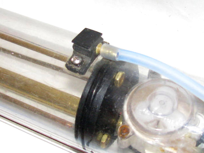
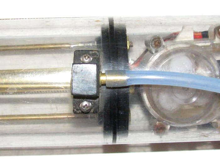
I have cut several pieces of sheet plastic.
They have been cemented together and are currently in the vise.
Here are the raw plastic parts.
Top is the old part foot. contacts cylinder. (not going to use it)
Middle part is the new foot. (needs a couple more layers of plastic
so I can grind the cylinder diameter in to it.
Bottom is the valve distribution body.
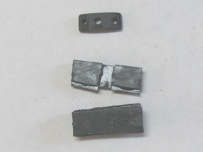
Parts in progress.
Top is the part that will seal the unit after all the ports and tubes
are in place.
The Distribution body.
It has a groove so I can get the air input and the air venting
in tot he cylinder.
The foot has a hole in the middle to feed the distribution slot.
Bottom is the intake air tube.
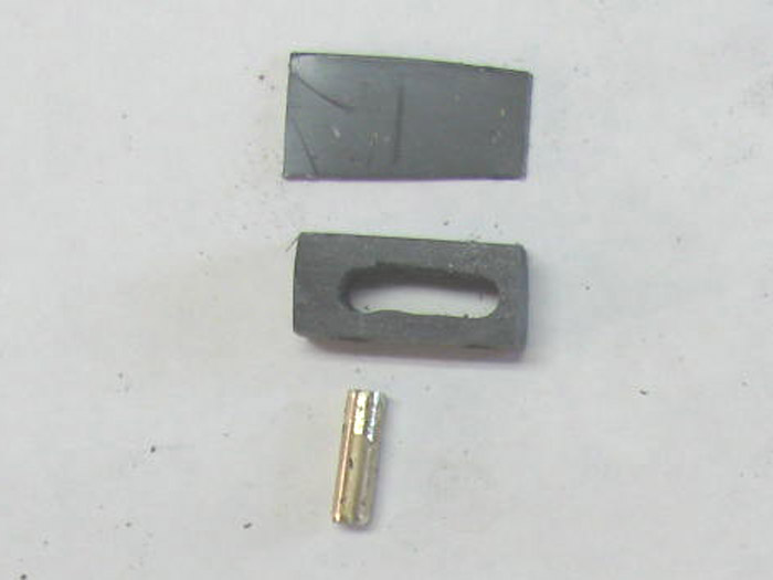
Air intake tube bonded in place.
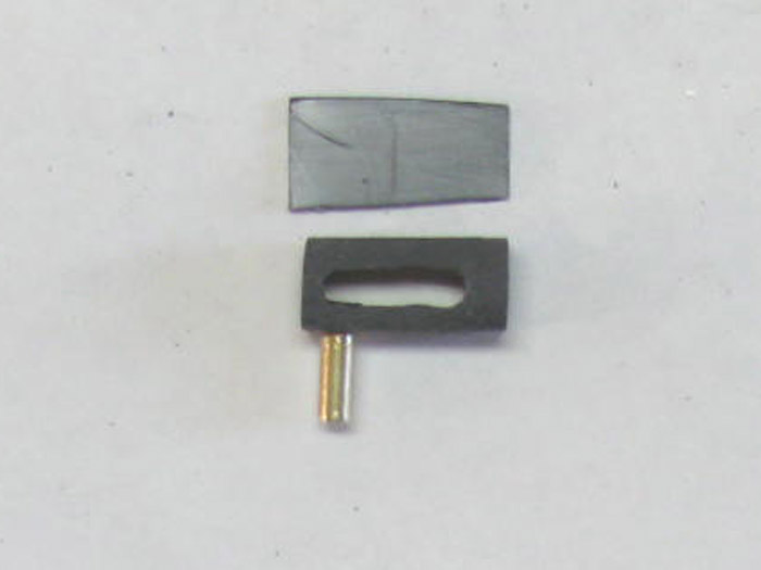
The foot has had 4 extra pieces of sheet plastic added.
Two pieces on each side. It is in the vise, again.
February 24th =================================================
These three parts make up the air intake and the vent distribution body.
Part on left was sanded to fit the cylinder curve.
Using 160 grit wet and dry sand paper, I moved the part back and forth
on the sand paper which I had wrapped over the short cylinder piece I have.
I drilled the hole to fit the brass tubing piece.
The inside diameter is 3/16".
It is flush on the top side and the brass tubing sticks down 3/32"
which will drop in to the hole in the cylinder to hold the part in place.
The part in the middle is the distribution section.
The brass tube is the air inlet which will have the rubber fuel hose
attached from the air pump.
The hole will become the vent valve with a cover that will be moved
by a servo.
The part on the right is the plastic cover that goes over the distribution
body.
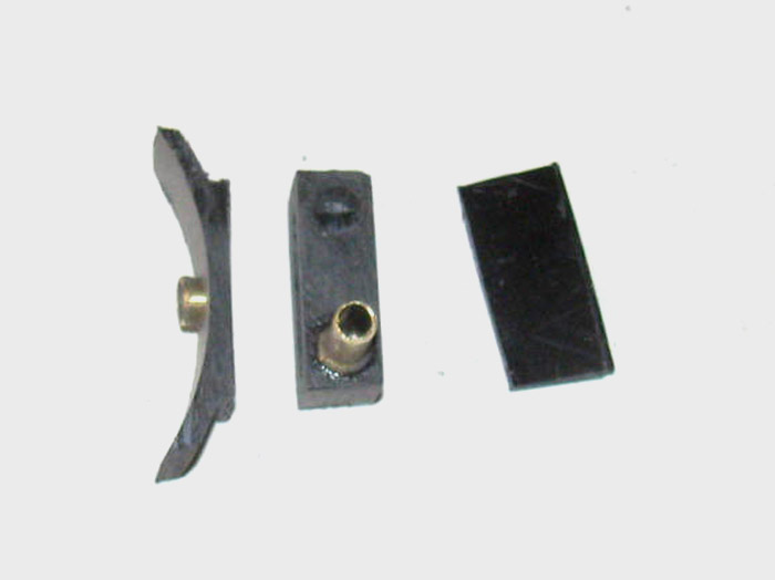
Another view of the parts.
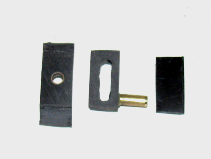
The parts assembled
After the cement cures I will clean up the sides of the part.
Next I will drill 2 small holes for the bolts that will hold the distribution
valve on the cylinder.
Using the part, I then can drill the 2 holes in the cylinder and tap
the holes with one of the bolts.
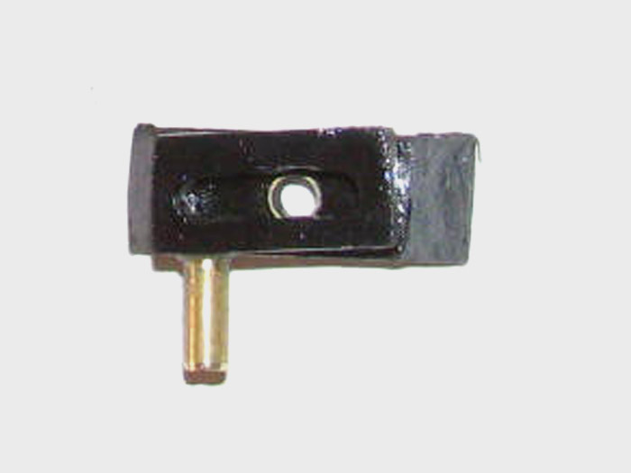
February 25th =================================================
The distribution valve body has been cleaned up.
The two holes for the mounting bolts have been drilled.
One mounting tab turned out to be too thin.
Made a plastic shim and it is currently in the vise while it cures.
To drill the 2 holes in the cylinder, I needed to remove all the electronics
from the cylinder.
This included the ballast tank frames.
While the ballast tank frame is out of the cylinder, I decided to lengthen
it another 1/4".
When trimming, I had the volume so close that there was no reserve
buoyancy.
I would have to hit the surface waterline exactly and get the fore
and aft pitch exactly.
Now I should have enough between surfaced and submerged trim to be
able to move ballast weights fore and aft that I can get to trim a little
faster without upsetting trim so much.
Now to order the air pumps.
Going to get pumps for the Gato and one for the George Washington refit.
February 26th =================================================
Distribution valve cured.
Sanded the bolt tab and drilled hole for mounting bolt.
Set the distribution valve body on the cylinder placing the the brass
tube on the bottom in to the hole in the cylinder.
Drilled one side and installed bolt.
I used the bolt to cut the threads in the soft cylinder wall.
Just go slow when doing this.
Drilled second hole and threaded the hole.
Here the distribution valve body is installed.
The brass tube on the left (1/8" id) is the air inlet coming from the
air pump.
The hole on the left will be the vent valve to release the air from
the ballast tank.
I have some parts to make.
There will be a brass tube with a plastic end fitting that will have
the rubber seal material that will cover the hole in the distribution valve
body.
The brass tube will go to the back of the cylinder through guide to
the end cap.
A servo will pull the valve seal away from the distribution valve body
opening the hole to vent the ballast tank.
Servo to center and the valve will close from spring pressure.
Move the servo in the other direction, it will touch a micro switch
turning on the air pump(s) filling the ballast tank with air.
I have not decided it I will use a fuel hose to vent the air in to the
conning tower or let it vent under the deck.
I don't think it will matter other than more tubing above the waterline
during surfacing will require more positive buoyancy.
Like I don't already have enough trimming issues.
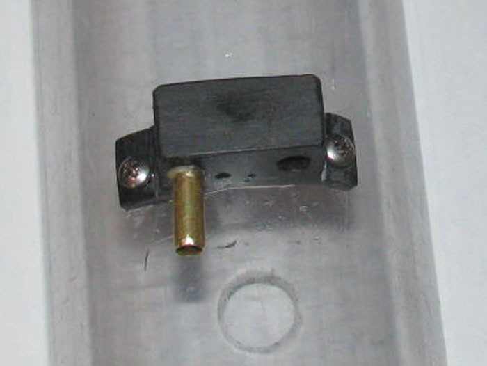
Note about photo.
Just right of the brass tube there are 2 black spots.
Those are water spots from washing the cylinder after drilling and
threading.
The ballast tank frames and spreaders have been pushed in to the cylinder.
The distribution valve body is now installed on the cylinder.
-------------
I learned something I have not heard before.
I was testing cement, glue and CA on a piece of scrap Polycarbonate
cylinder.
I was testing because I have a couple control rod guides I need to
mount on the top of my cylinder and I don't want to use screws or bolts.
Here is what I learned.
The glue and cement did not hold up.
The CA melted in to the cylinder and left a noticeable reechoes.
I think if I was to put a drop or two more, it might eat all the way
through the cylinder wall.
NOTE: do not use CA on Polycarbonate cylinders.
My conclusion will be to continue using silicone glue by taping the
area I want the silicone to bond and sanding it with 200 grit wet dry paper.
Then applying silicone to the part and pressing on to the sanded cleaned
area and clamp in place over night.
----------------
The CA testing was an accident.
I had used CA on a couple of parts and I laid them across the hull
to cure.
I did not notice the CA dripping on the far side and on to my little
test cylinder.
The test cylinder (2" long) is used to test fit end caps with o-rings
when I make the end caps.
February 29th =================================================
I was at the pond today.
There was Will and myself.
It was not a scheduled gathering but it was "I just wanted to get out
of the house."
Same with Will.
I took only my Akula II so I could try various maneuvers to see how
the new rudder extension performed.
Will Bought one of his tug boats to test the Z drive pods with a new
Tx and see how the boat turned with the pods linked instead of individually.
His boat was turning in less than 2 boat lengths in forward and it
sat in one place when turning in reverse.
Then a servo stopped working and the boat was hauled out.
Will had a second surface boat that always performed well.
Back to my Akula II.
Last time out, I had issues with the speed of the main motor.
It was too fast.
I could not move the throttle stick more than 3 notches and your would
think I had water skiers behind.
At the end of the day, Will took the little gizmo I got from him to
take home and see what was wrong with it.
This morning, He showed up with the little Gizmo and another bigger
Gizmo.
By big, I mean 3/4" square.
These are pots to limit the amount of in put to the speed controller.
Will had set the pot at home on one of his boats.
He set the Gizmo to put out the lowest input to the speed controller.
Installed in to my Tx and tested it on the table.
It visibly ran the main motor slower.
Prepped the boat and in to the water.
Did the dive surface dive surface to get all the air out of the piston
ballast tank.
Next I submerged the boat to near decks awash to get the upper rudder
down in the water.
Will asked me to give the throttle, 1 notch and then push the slider
up.
At about half way up on the slider the propeller started turning.
It was turning so slow, the boat did not move forward.
Will asked for 1 more notch on the throttle.
The boat started moving forward but very slowly.
The boat barely made a wake.
Now he wanted the throttle moved forward slowly until I got to full
throttle.
This is something I could not do before.
Full throttle would make the boat fast and out of control.
I couldn't do this.
At full throttle, I was asked to bring the slider back to center.
The boat was not fast but fast enough to get out the way of others
and be in full control.
Now cruising the pond, I had the full range of the stick and not just
the first 2 notches.
And with the slider and 1 notch, the boat moved enough that I had rudder
control.
Now about the rudder.
You remember I made an extension before last time out.
This one.
[img]http://www.cliffhangershideout.com/Akula/rudder21.jpg[/img]
Okay now a report.
At minimum turns on the propeller, I could turn in both directions.
The turning radius at this speed was about 8'. EIGHT FEET!
This was not possibly . . .ever before the modified rudder.
Push the throttle up 2 notches more and the boat still turned in less
than 10'.
In fact, I found that if I eased up on the rudder a little, the turn
tightened up.
I could run about 6' out away from the concrete lake edging and I could
turn in to the shore and finish the turn before the boat hit the concrete.
I have real maneuvering now.
With the fish tail rudder, there is water pressure on both sides all
the time.
Any moving of the rudder gets immediate response in to a turn.
No more 40' to 50'.
I now have 8' and less turns.
And this was the same when the boat was surfaced with the top rudder
out of the water.
I like it, I plan to keep it.
I will take the time to clean up the installation.
March 1st =================================================
Everything in the cylinder has been disassembled.
Working on getting the needed two air pumps.
It looks like work will stop until I have the air pumps in hand.
I may need t make a new aluminum electronics tray for the rear compartment.
I need to get 2 air pumps and 1 more servo in there.
The roller pump/motor and it's speed controller might be bigger then
the 2 air pumps and servo.
But I think I may move the main motor forward and install all 3 servos
between the motor and the end cap.
I can gain up to 1/2" to 3/4" in the compartment.
If I can do that, that means I can move the ballast tank frames back
that much moving the center of gravity of the ballast tank towards the
stern.
Than also means moving lead ballast weights back as well.
But, I will not know for sure until I have the pumps in hand.
------------------
So, today, I drained the test tank/safe.
The next couple of days the weather is suppose to warm up.
I will sand the inside of the safe tomorrow and get it ready to paint.
Then Wednesday, I will get at least 2 coats of paint on the inside.
Wait a couple of days, and then do the outside.
This should keep the water clear.
Right now, I can not see the bottom at 14" due to the rust suspended
in the water.
This does give the hull a natural weathered look.
I might even clear coat over that for the look it is getting.
March 3rd =================================================
Last night I sent an e-mail to Nautilus Drydock with questions about
the web site ordering procedure.
This morning I woke up to an e-mail from Bob Martin explaining how
to deal with my concerns.
I read his ordering instructions and I wrote another e-mail telling
Bob I was sending the order in.
Within minutes, I got a response from Bob.
He got the order and was in the process of boxing up the parts for
shipment.
The problems I have with ordering is I do not have a street address
for shipping.
It all goes to the post office in town.
Other countries do not/will not ship to a PO Box.
They do not get I am 14 miles from town and my POB.
We have no mail delivery out here.
Back to Bob.
He understands the issue and my parts will be shipped.
Thanks, Bob of Nautilus Drydock.
So, it looks like I will be back to working on the Gato in few days.
I best get busy on repainting the safe/test tank so it is ready when
I get the new electronics tray built.
--------------------------
I finished outside for the day.
A lot of sanding with a palm sander, and my fingers.
50 grit and 120 grit wet/dry sand paper.
Ran the palm sander in one hand and my 120 psi air hose in the other.
Rust dust every where.
Good day to do it.
The wind is at about 10 mph and in a direction not to cover my house
or the guy next door down the road.
After a complete sanding (about 1.5 hours) I got out the paint thinker
and a clean rag.
Wiped down the inside surfaces to get all the dust off.
It is war m to day and the thinker was drying almost as fast as I was
wiping.
Let it dry for 30 minutes and then I got out the Gray primer/paint by
Krylon.
I used 1 can to get a first coat down.
Waited 15 minutes and the put the second coat down.
As I painted, I turned the box so the side I was painting was the down
side.
No up and down, just flat.
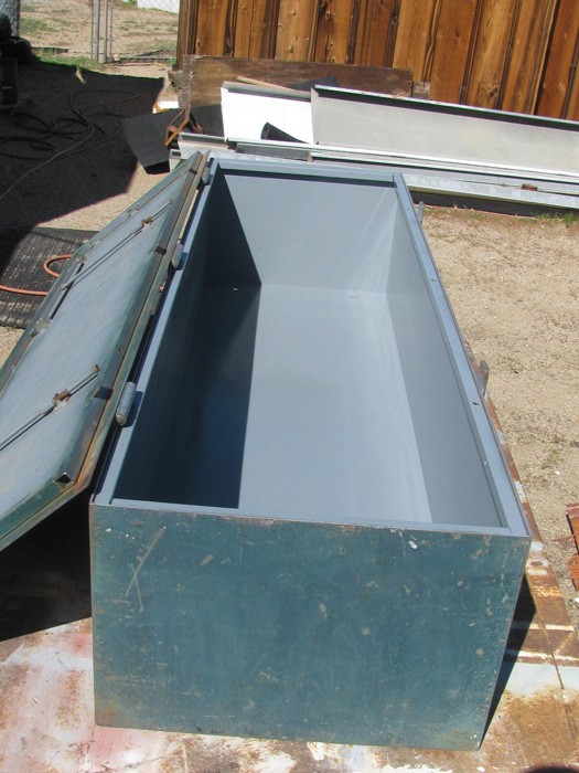
March 4th =================================================
In the photo in the previous post, you can see the inside lid is not
painted.
Well, this morning, I have sanded and painted the inside lid.
Going let it dry for 30 minutes then I will close it up and start sanding
the outside.
Got an early start.
I went out side to get a wrench from the shop and it wa warm enough
to paint.
Never made it back to the house with the wrench.
That can be done later today . . .or tomorrow . . . or when ever I
get back to it.
I am going to go put the green paint in the sun to warm it up.
--------------------------------
The safe/tank is now sanded.
Started with a belt sander and finished with a palm sander.
Used the air hose to blow off most of the rust dust.
Got out my rag and paint thinner and wiped down all the out side surfaces.
Painted the bottom flat black.
I did this because I do not think I have enough green to do the box
including the bottom.
Besides, I have lots of flat black in the shop.
Went on to paint the lld, two ends and one side, green.
Now to let this dry, before turning the box over to paint the one remaining
side.
I will be back when the painting is done.
I will take a photo when finished.
I may put another coat on later.
But so far I have painted the first coat and then after 20 minutes,
painted a second coat.
The paint I just took off by sanding was put on 1996.
So over 20 years.
This is the same pant but a new version.
It has primer in the paint so the job of priming first is gone.
--------------------------------
The painting is complete.
For now, anyway.
Here is a photo of the top and two sides.
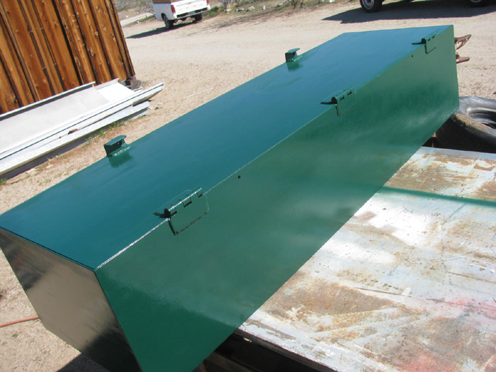
While I wait for the pumps to arrive, I think I will refinish the transportation
box for the Akula II.
The edges are looking a bit worn.
The only paint on my transportation boxes is primer. No paint.
So I think I will sand the box down and try painting with a MAtt Finish
Gray.
I couldn't find Flat Gray other than primer.
This should good quickly.
A quick sanding to clean up the primer and scuffed areas then paint.
If this one looks good, I will go the others.
March 4th continued ================================
Turns out I got the real life stuff taken care of and I am back in the
shop.
Might as well start on the Akula II transportation box.
Took the boat out of the box with it's masts.
Took the box and lid out to the outside work bench.
Got the palm sander out and I am ready to get after the box.
The box has 3 or 4 coats of gray primer on it.
This was the finish I wanted.
Old Military crate look.
But the primer is too soft and does not hold up to riding in the car.
Being slide on the park benches.
Bumped against, . . well any thing at all.
I just does not take much to scrap the primer off and expose the wood
under neither.
So I am preparing to sanded and PAINT the transportation box, Matt Gray.
I am in here posting this as the sanding and wipe down are complete.
The paint has been applied to the top and 4 sides of the main box.
There is 1 side to go.
The side that is sitting on the barrel where I am painting the box.
I will give it 30 minutes or so to dry and then I will turn the box
over and finish it.
I have painted the last side.
Here is a photo of the transportation box with it's new paint.
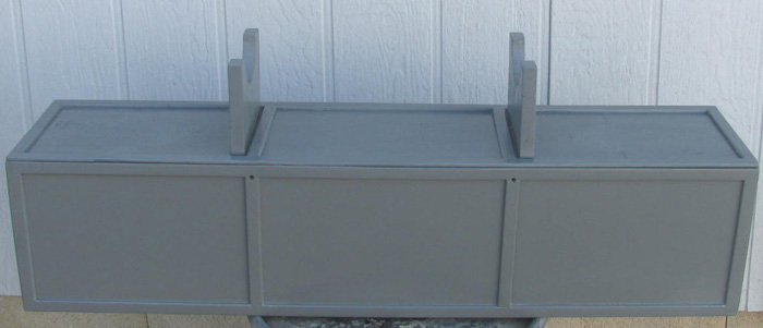
The Matt Gray paint looks like a match the primer gray color very close.
I am hoping the paint will take a little bumping with out exposing
the wood.
Time will tell.
March 5th =================================================
Today, I am working on the Skipjack transportation box.
Tomorrow I will do the Gato box and George Washington..
That will leave the Alma box but right now I am using it as a stand
so, it will have to wait.
Good news.
I was in town this morning and stopped at the post office.
In with my mail was a small box from Bob Martin. (Nautilus Drydock)
I order 3 air pumps first of the week and they are here.
I can now get back to rebuilding the aft electronics tray.
The size of these pumps is smaller than I thought they would be.
This means I will have more room in the cylinder and I can move the
ballast tank back a little more.
Okay, I have to finish the transportation box repainting before I can
get back to the Gato.
The boxes take up a lot of room on my work bench.
Well, they take up all the room on my work bench.
I need to get the boxes done so I can finish the Gato.
This the only way I will be able to clean my work bench and find all
the little parts missing on the bench.
Some of these parts are not small.
I cleaned off all the rubber from a Schreader valve.
Bright and shiny brass part.
10 minutes later I went to install it in an end cap.
I could not find it.
I had to clean another Schreader valve to out in the end cap.
It's there some where.
I did not leave the shop when this happened.
The work bench is a mess.
The Gato has been on it for over a year now.
Not it's fault.
All the hospital stuff slowed this down severally.
Okay out to the shop.
No work getting done in here.
March 5th ---- still
The emblem badge has been reinstalled on the Akula II transportation
box.
Here is the original installation on primered box.
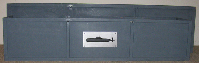
The Skipjack transportation box has been sanded and wiped down with
paint thinner to remove dust.
Let it dry and applied the Matt Gray paint.
I got 2 coats on.
Will let sit over night and see if there needs to be a third coat.
The other transportation boxes are going to have to wait.
I want to get back to the Gato electronics tray.
------------------------------------------
Here is a link to how I make the Badges for the transportation boxes
and the Tx suit cases.
They are some what 3D.
[url]http://www.cliffhangershideout.com/box-badges/badges.html[url]
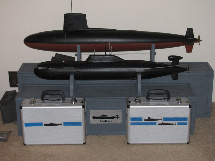
I noticed that the cases are incorrect in this photo.
The case on the left runs the AKula II and the Skipjack now.
Both boats have Engel's piston ballast systems in them.
The case on the right runs the George Washington and is also setup
to run the Gato.
The correct badges are on the correct case now.
March 6th =================================================
Painting complete.
Today is sunny with light clouds and NO wind.
55 degrees.
Out to the outside work bench.
Brought the Gato transportation box to the bench and then the palm
sander went to work.
Sanded the box, blew the dust off.
Wiped down with rag and paint thinner.
Place the box on a barrel and the lid on another barrel.
It is now time to paint.
Painted 2 coats or more on all surfaces.
Finished the painting.
What?
The clock says it's only 8:50 am.
The weather is still holding and now warmer.
Okay, get the George Washington Transportation box.
Remove the box badge.
Out to the outside work bench.
I had not yet put the palm sander away.
Attack the lid.
Attack the box.
THis took about 10 minutes.
The GW is a small boat.
It's 1/144 scale.
The box is so small the sander will not fit between the supports on
the box both ways.
So, there was a little hand sanding with a wooden block.
The box is now Matt Gray.
Will let it dry for 30 minutes or so before moving it in to the shop
for over night curing.
With the Skipjack, Akula II, Gato and now the GW boxes in the shop,
there is no room to work.
This is okay because I have in town stuff to do to day and had only
planned to do the Gato box.
Tomorrow, I should be able to start putting the boats back in their
transportation boxes.
I think that will be a good time to take photos of each boat on top
of it's box in the lid stand.
Currently I have to be very careful in my living room.
There are boats every where on the floor.
I did put them near the wall in an area where I do not walk.
Unless I sleep walk, they should be safe until tomorrow.
Photos tomorrow.
Boats and Boxes.
---------------------------------
I thought I would get a group photo before moving all the boxes back
in to the shop.
Boats are not in the boxes.
I want the paint to cure completely so there is no transfer of paint
to the boat hulls.
From top down.
First is George Washington in 1/144 scale.
Second is Akula II in 1/125 scale.
Third is Skipjack in 1/72 scale.
Fourth is Gato in 1/72 scale.
The blocks on top of each box is a hinged stand to hold the boat for
display and at the pond.
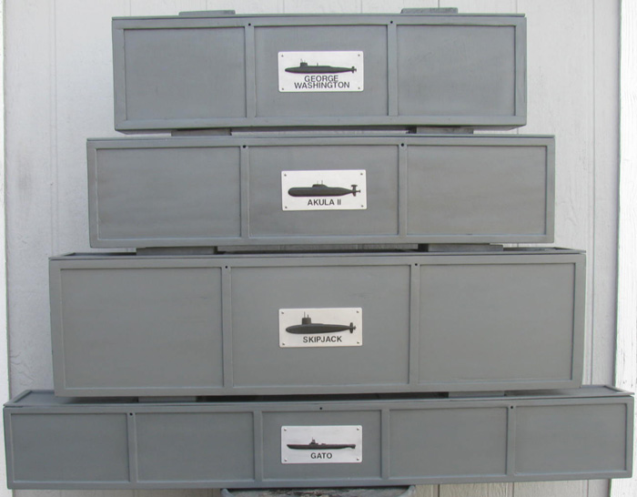
March 7th =================================================
Paint on the transportation boxes is dry enough to put the boats back
in them.
But while I am doing this, I will take photos of the boats on the box
lid stands.
Here is the 1/144 George Washington. Overall length of boat is 31.75".
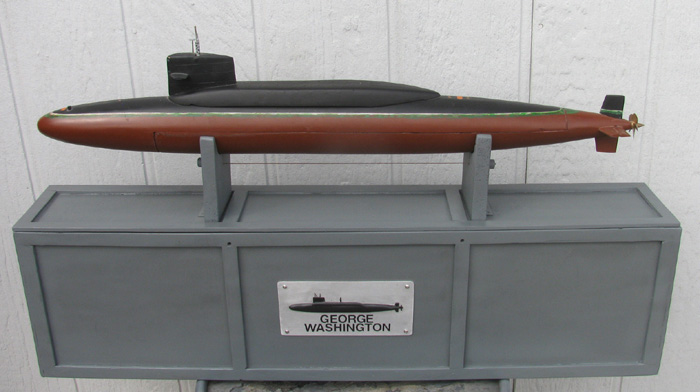
Here is the 1/72 Skipjack. Overall length of boat is 42.25".
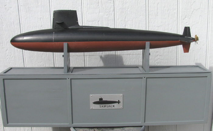
Here is the 1/125 Akula II. Overall length of boat is 34.50".
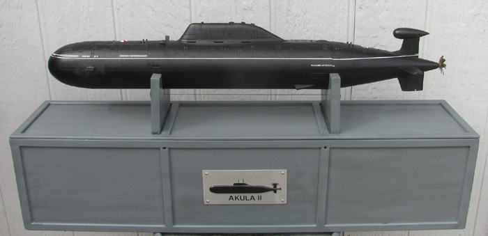
Here is the 1/72 Gato. Overall length of boat is 52".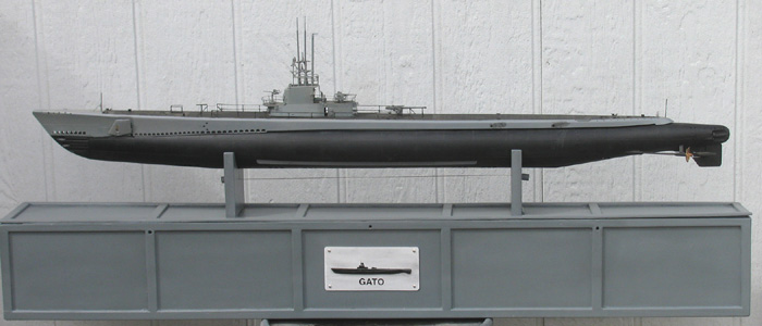
The stands are screws to the box lids with a hinge so the stand prices
will lay down towards the ends of the box.
When standing there is a cable between the stand pieces to keep the
from falling over.
I use bungee cords at first but I had one stand end fall over as I
was putting the boat on it.
The boat was safe because I had not let go yet.
The cable is 150 lb fishing leader cable.
I cut 2 1/2" wooded dowel pieces about 3/4" long.
Drilled a small hole through the wooden pieces.
Just large enough for the cable to go through and back again.
So tight, I could not pull the cable through once it was doubled.
Applied a little CA.
To measure the length between the stands, I first cut a slot in the
center of the stand with a hacksaw blade.
The cable has to be forced down by moving the cable back and forth.
Slipped the second wooden piece on the end of the cable and folded
it back through.
Pulled the cable tight against the stand end.
Just enough to have a slight pressure on the cable.
CA on the cable in the wooden piece.
Put one side in and then pull the other stand towards the middle and
using the wooden dowel piece, I can put the dowel ad a slight angle and
it will slide down in to the slot pushing the stand piece in towards the
middle.
In the photos above, your can see the wooden dowel pieces and cable
below the boat hull.
The cut slot is about 1" deep.
Enough room to get my fingers between the hull and the cable.
March 8th =================================================
Did some searching for aluminum sheet.
What I have been using for years is 1/8" thick none flexible. (good
thing)
I wanted to find aluminum sheet that was thinner.
Turns out Lowes Hardware has 22 gauge in small pieces.
5" by 18" and it's 6063 T4.
Not that the transportation boxes have been repainted I can get back
to the Gato rear electronics tray.
I will disassemble it tomorrow and see if I can rearrange everything
to get 2 air pumps and 1 more servo on it.
It also looks like I may have to move some of the through end cap tubes
to get 1 more through it.
Or make a new cap.
This morning I went to Lowes and picked up 1 of those aluminum sheets.
It seems a bit flexible but beings I bend the edges over to give my
electronics trays strength, this may work.
22 gauge is roughly 1/32" thick.
I was thinking I might try to get the propeller motor farther forward
so I can mount 2 servos behind the motor with the drive shaft going between.
The 3rd servo would be in front of the motor and the speed controllers
in front of all this with the Rx.
My reasoning is during trimming, the stern was a bit heavier than I
would like.
Took more foam back aft.
But I did get a perfect trim submerged and near perfect surfaces. (low
stern)
I also picked up some straight inline wire plug connectors.
The plugs I have now are big.
I have to unsolder one end to remove the rear electronics tray.
The plug will not fit through the brass through tube in the ballast
tank.
I think these inline plug connectors may go through the tube.
Sure hoping they will.
Of course if the equipment works as it is designed, I may never have
to remove there rear electronics tray again.
So I have things to do this next week.
I will get as much done as I can.
The week after, all that hospital stuff starts up again.
This time they plan to work on my eye.
This all started last May and so far nothing has gotten done.
I would like to see with both eyes again.
Anyway, building will continue.
March 9th =================================================
And now the modification begins.
Here is the rear electronics tray removed from the cylinder.
The roller pump (left side of photo) and it's speed controller will
be remove and replaced.
\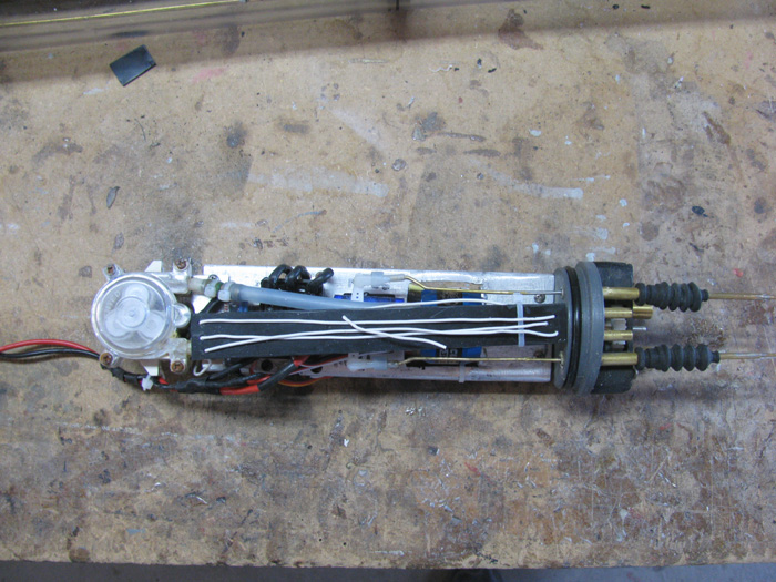
Replacing the roller pump will be these 2 air pumps and a servo.
I have not yet decide if there will be a speed control or just a couple
of switches to run the air pumps.
My plan is to make it a two stage unit.
Servo will move and contact first switch.
Move input on servo will then contact second switch.
Servo in other direction will open ballast tank vent valve. (to be
worked out as I go)
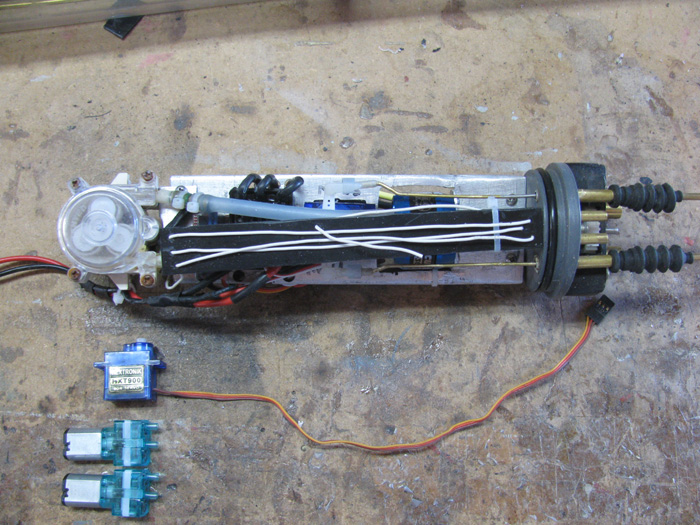
Now the rear electronics tray has been stripped of all equipment.
I was shortening the main aluminum tray by 3/8" at the end cap.
I also needed to decide how to get the extra servo control rod through
the end cap which did not have enough room to make another through hole.
So before I make a new end cap, I am going to modify this on.
I removed the 2 control rod through brass tubes.
I also removed the 2 water inlet/outlet brass tubes. Looks like I will
be using a smaller diameter brass tube for the water inlet/outlets.
The air pumps have smaller inlet/outlet on them
My current fuel hose tubing slides on and they fit loose.
Back to the end cap.
The first thing I did was shorten the main propeller shaft bushing that
was sticking 3/8" in to the cylinder side.
It is now it is only 1/32":.
This process to remove the tubes only requires taking another brass
tube the same size and slowly tapping the tube to be removes with a small
hammer.
1 or 2 taps and the glue that bonds the tube in the end cap releases.
Take a small round file and I filed the inside of the through holes
to clean them out and make the surfaces rough for next bonding.
Took the end cap and a large half round file and cleaned up the outside
on both side of the end cap.
Place tape over all 4 holes.
Dropped a small amount of baking soda down each hole.
Using a 1/16" brass rod, I dipped the rod in to the medium CA glue
and dropped the glue to the bottom of each hole.
Let this set up. (does not take long.
Now I drop a little more CA in each hole and then drop a pinch of baking
soda in to each hole.
I do this in several steps until the CA comes up to the top of each
hole and then I add another drop to make the glue high and sprinkle a little
more baking soda.
I will let this cure over night and then file it all smooth.
After this is done, I can locate and redrill the new holes for the 3
control rods and 2 air tubes.
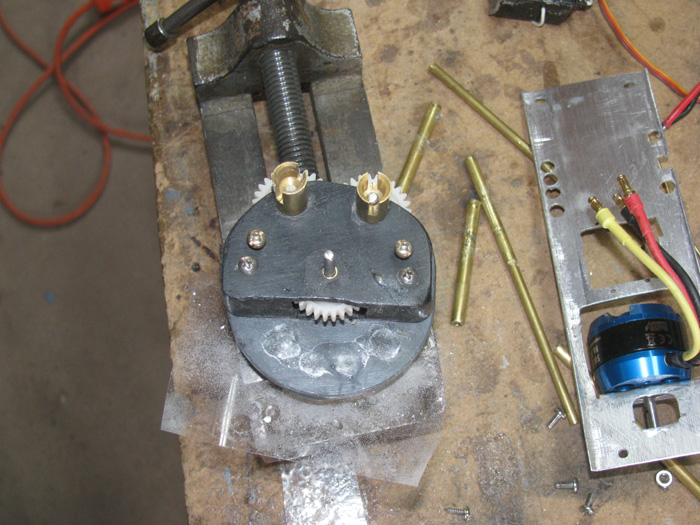
March 11th =================================================
Sanded the CA glue down flush with the end cap.
Laid out the location of the new holes for the 3 control rods and 2
air tubes.
Got the air tubes in and got 2 of the control rod tubes in.
There was very little room for all of this.
I was going to use rubber boots for the control rods.
Well, the last hole did not go well.
After drilling the hole ad checking the size and depth, I slipped the
brass tube in for fit.
Nice but then I see this bright shiny brass color down in the o-ring
groove.
Yep, the hole cut in to the groove slight lightly.
Farther checking I see a second brass tube was barely peeking through
the o-ring groove.
Thought about it for a couple of seconds.
New end cap has to be made.
Okay, I can do that.
So while I consider making a new end cap, I look over the gear box.
(photo above)
It looks like I can sand the top edge (edge where the gear sticks out)
down to within a 1/4" of the gear shaft and 2 mounting bolts.
This will give me 3/16" more room on each side of the end cap.
I also am going to not use the rubber boots and I will cut recesses
for the o-rings in the end cap and use a compression plate to hold them
in place and squeeze them slightly around the control rods.
After I make the new end cap, I will see if the rubber boots will fit
or go with the compressed o-rings.
I can do either.
With the end cap unusable, I got the parts to make the third control
rod.
But I did not assemble it.
I don't know how long it needs to be until I get the end cap made and
the parts mounted on it.
I don't know where the servo will be located.
-----------------------
While doing this and other things, I was thinking about these small
air pumps.
There is a way to make the boat a negative boat and have the means
to bring it back up.
I have a third air pump which is for the Gw boat.
Not as I reassemble the Gato, if I have room, I can install the 3 pump
so it draws air from inside the cylinder and pumps it in to a bag outside
the cylinder maybe in the ballast tank.
There would need to be a servo, a micro off/on switch and a Schreader
valve to release the air from the bag back in to the cylinder after the
boat breaks the surface and the other pumps get outside air to fill the
ballast tank.
It is just something I got to thinking about.
March 12th =================================================
This morning, I cut a new slab of gray PVC rod.
It will become the new end cap.
I need to add a bit of plastic on to the gear box.
When I removed material yesterday, I did not think it through.
I cut more than I should have.
It exposed the propeller shaft cup seal by 1/32".
I will build up the area on the gear box that will cover the seal and
finish smooth.
The seal needs the compression from the gear box to make the seal do
it's job.
This afternoon, I hope to get out to the tool shed and turn the end
cap.
If not, I have all of tomorrow to work on it.
Turning end caps takes about 30 minutes.
I only have a drill press and hand made cutting tools.
This is how I have been doing it for many years.
Today is the first time in years that the weather prediction is right.
Weather said rain starting about 10:30 am.
It's 10:22 am and it has started raining.
Not hard but steady.
Got things in town at the post office I need to get.
Medical stuff.
Timing is good because I will run out Saturday.
Can't let that happen.
I see that doctor next Monday.
Hoping to get approved to return to the eye surgeon to get my eyes
fixed.
I would like to see again.
If nothing else gets done today, I got my 10 minutes in for the day.
Since 10:25 am it has been raining and the temperature has not gotten
above 48F degrees.
I am not out in the shop.
March 13th =================================================
Still cold (46F)
Still wet but not raining.
No wind at all.
I am ready for trip in to town.
I thought while I have my heavy coat and long sleeve shirt on, I would
brave the outside and go out to the shop and see if there is some thing
I can do before having to leave.
I picked up 3 pieces of scrap sheet plastic.
3/4" long by 1/4" wide and 1/16" thick.
I cut the largest pick for the backing support.
This piece will hold the 2 pieces flush on the gear box edge and it
will go down in to the gear box about 1/8".
Squared up all the edges.
Put in the small table vise.
Using a round file, I put a notch in the center of the long edge that
the gear hub will fit in.
The gear hub has single layer of blue masking tape to keep the plastic
from touching when running.
Rounded the two top corners to make it look nice.
Cleaned up the inside edges on the gear box where this part goes.
Cut the other 2 pieces to length to match.
Applied the plastic cement bonder to the gear box and the part.
Set the part down on the gear hub/tape.
Held it in place for a few seconds while it got tacky.
Removed the gear shaft and the gear.
Held in place a few more seconds.
Then I put a large paper clamp on the part and gear box.
Set it aside and moved on to the 2 pieces of plastic that will sit on
the gear box edge and against this new support piece.
I did this because I do not think 1/8" pieces butted up against each
other will have enough strength top push down on the cup seal edge.
Applied cement blond to the 2 pieces and placed them in the table vise
and clamped them together.
Later today, after they cure some, I will fit them together to make
sure I get a good connect bond.
Then I will cement them together.
After they sit over night, I will sand the pieces flush with the rest
of the gear box side.
And I will shape the 2 outside pieces to match the support piece.
----------------------------------
Then it will be time to make the end cap.
Last night I had time to think about this and I made a change to where
the 3 rod bushing and 2 air inlets will go in the end cap.
The new positions should give me more room between the tubes and more
distance from the cap edges and o-ring grooves.
The new position will give me a better line up of the rudder and stern
planes push rods.
Such little parts taking so much time to make and assemble. (bonding
cure time)
Here is the gear box and the small part needed to cover the shaft cup
seal.
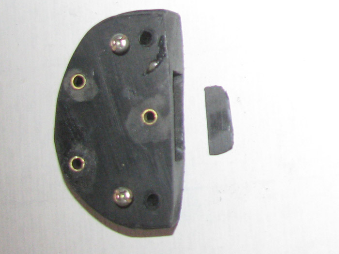
Here is the gear box with the small part cemented on.
Tomorrow, I will finish shaping it.
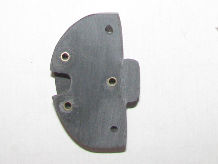
March 14th =================================================
I am in the shop preparing to make a new end cap.
But while doing this, I was thinking about how I was going to make
this boat a negative boat using a third air pump.
The third pump would pump air from inside the cylinder in to a balloon
inside the ballast tank to get the boat up to periscope depth to get air
from the surface.
Then the other 2 air pumps would fill the ballast tank with outside
air and the third air pump or balloon could be emptied back in to the cylinder
for the next surfacing.
Required equipment.
Air pump, air ballast balloon, a Schreader valve or some other valve,
a switch to turn the pump on and wire from rear compartment to the front
compartment.
This all takes room.
Then while getting ready to turn the end cap, I had a thought.
On my office wall with other sub stuff, there is a hand drawing that
could work if I can make the thing.
The drawing is of a snorkel system that will bring air from outside
the cylinder or if the mast is submerged, it takes air from in side the
cylinder.
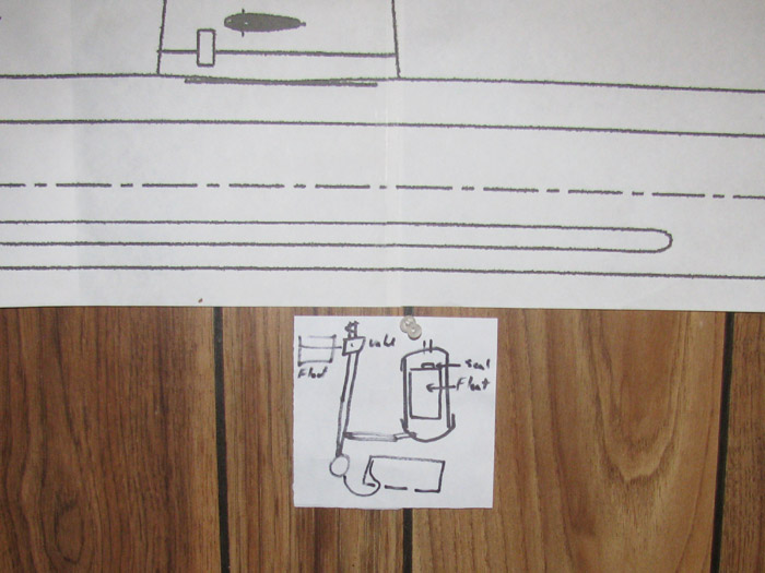
It requires two units.
One in the boat and one on the intake mast.
I need to look and see if I can fit the mast float in the conning tower.
If so, then I will make the unit that goes inside the hull.
Thought about it last night and the inside unit will eliminate having
to make 2 manifolds for air hoses.
The unit can be 1 of the manifolds.
To start I need several squares of plastic sheet.
I cut 10 which I will use 5 for each unit end cap.
There will be more to make the covers which will have brass tubes installed
for air hoses.
I have applied cement and the 2 parts are in the vise and compressed
to cure.
THe start of the needed squares.
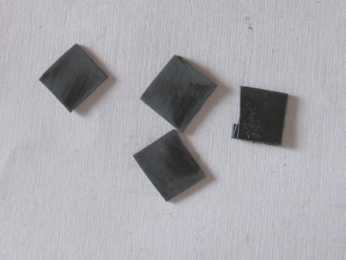
Yes, I have my camera working on this as well.
On the right are the two blocks for the bases.
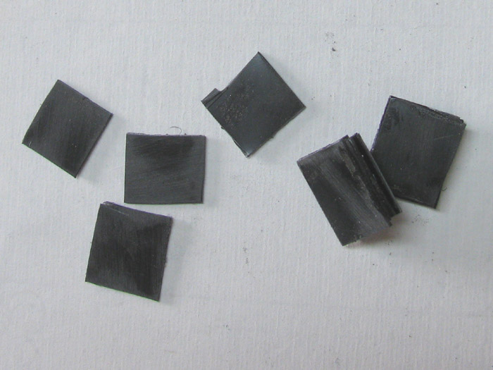
--------------------------------------------
While the cement cures, I have started in on the new cylinder end cap.
The end cap has been OD turned and ID shoulder turned.
Now ready to cut the o-ring groove.
Just need to line it up and make the cut.
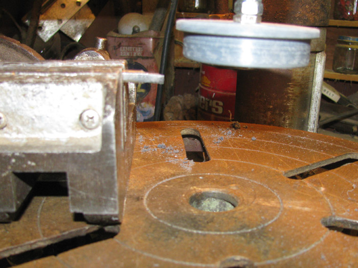
Cutting the groove.
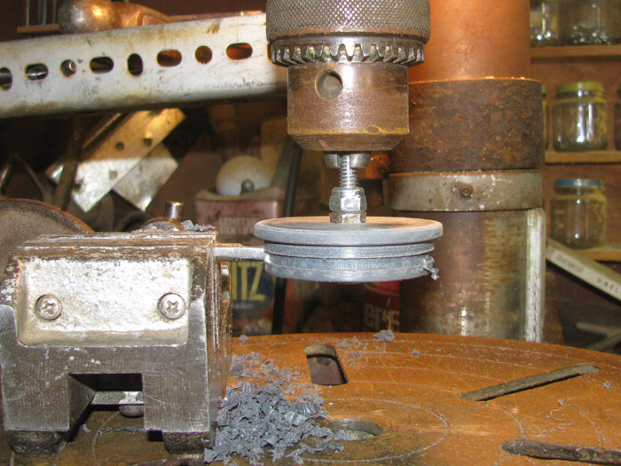
After cutting the groove and sanding it smooth, I tested the o-ring
fit.
Sorry about the blurry image.
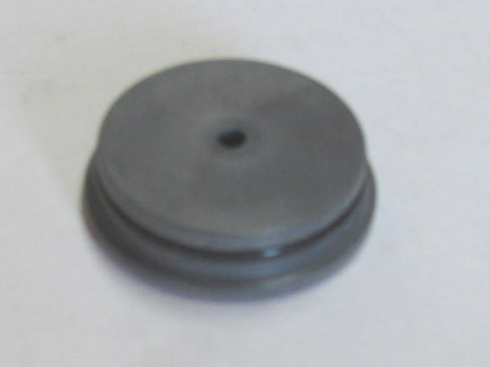
Test fitting the cylinder on the end cap wit o-ring.
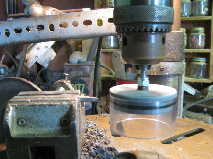
Next I need to fill the 1/4" spindle hole.
Clear packing tape on the outside of the end cap.
A couple of drops of CA glue.
Sprinkle a little baking soda in on the CA.
Another drop or two of CA.
Followed by a little baking soda.
Continue until the hole is filled.
Take a paper clip and straighten it out.
Use it to poke down in the hole to break up the air pockets created
by the baking soda.
Fill with CA glue until I have a small bump on the end cap surface.
that I will sand down after it cures.
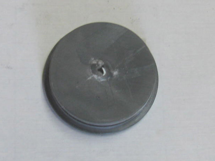
When cured, I will start drill in all the needed holes for the shaft
seal, 3 control rods and 2 air tubes.
The Shaft seal will take the most time.
I will drill a hole center of the end cap to accept the brass tubing
that will be the shaft bearing.
It will not go all the way through.
It will be short on the outside by the thickness of the shaft bear.
The brass tube will be 1/8" ID.
I will glue this in place and let cure.
Once cure I will use the brass tube to put the shaft of my seal cutter
in.
I will cut the end cap to accept the cup seal with the seal slight
up out of the cap.
The gear box will tighten down on this edge of the seal compressing
it slightly to effect the seal of the propeller shaft.
When I drill for the control rods and air tubes, I will put 2 guides
on the drill press so tI can not drill holes in to the o-ring grooves.
Did not do that the other day and it cost me my end cap.
March 15th =================================================
The end cap hole filler has cured.
The hole has been drilled for the propeller shaft.
The brass tube bushing has been fitted allowing room to cut the recess
for the cup seal.
Glue has been applied and the bushing has been set to the correct depth
in the end cap.
Moving on.
I have an idea for the air pump manifold.
I have seen others make brass tube manifolds which require short fuel
hoses to attach.
My idea is to make a plastic manifold that the air pumps mount to directly
with no hoses.
This is the start.
Cutting plastic pieces which I will bond together and shape.
It will be made in 3 sections before assembling.
The center section will need 2 channels.
1 for inlet and 1 for outlet air.
The manifold will also be the mounting bracket for the 2 pumps.
Part 1 is made up of 3 plastic pieces.
Part 2 is made up of 3 plastic pieces.
Part 3 is a single plastic piece which will be the cover after all
the channeling and inlet/outlet tubes are in place.
The parts that need to be bonder are and are in the vise to cure.
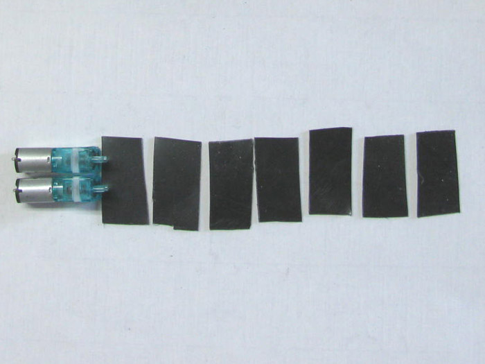
March 17th =================================================
I have drilled the holes and channels for the manifold.
2 Air Pumps, 2 temporary brass tube inlet and outlet, pump mounting
bracket, air manifold body and the cover plate.
The manifold channels where drilled at the same time the 4 pump mounting
holes and 2 inlet/outlet holes were drilled.
Using a flat steel bar on the drill press table as a guide, I pushed
the plastic piece from lower hole to lower hole.
Then moved the guide and did the upper holes.
After that, I pushed the plastic piece to connect the inlet and outlet
holes to the appropriate channel.
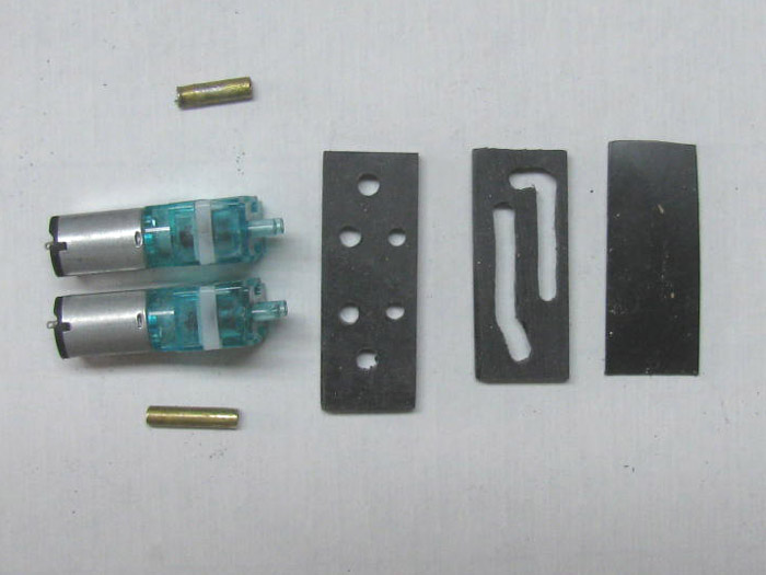
Test fit assembly.
The brass tubes will be longer to extend out to the motor ends for
hose connections.
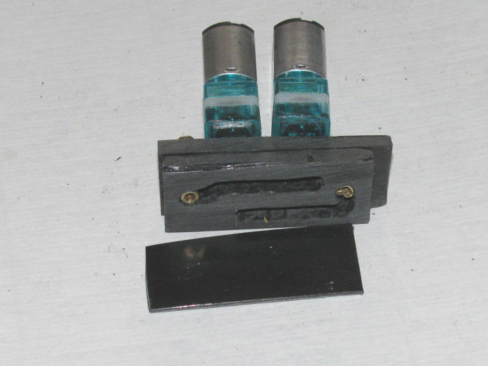
Pump and manifold test fit.
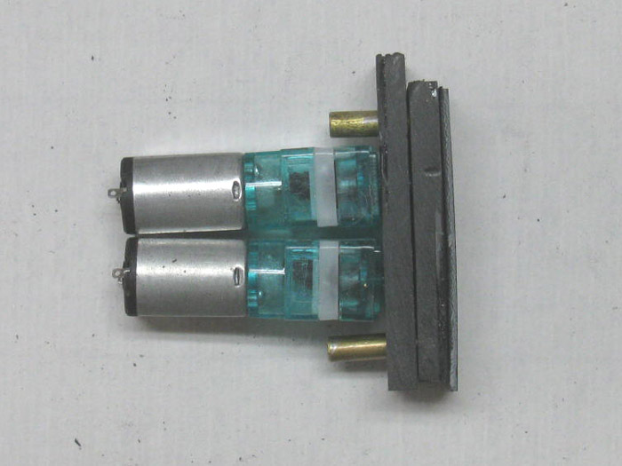
The mounting bracket and the manifold channel plate have been bonded
together and are in the table vise for curing.
This assembly will leave enough room to put the vent valve servo over
the assembly.
------------------------
Still time to go find some thing else to do.
March 17th continued =============================================
I am taking off all the rubber from a Schreader tire valve.
It will become the ballast tank vent valve.
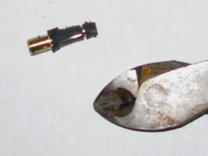
All of the rubber has been removed.
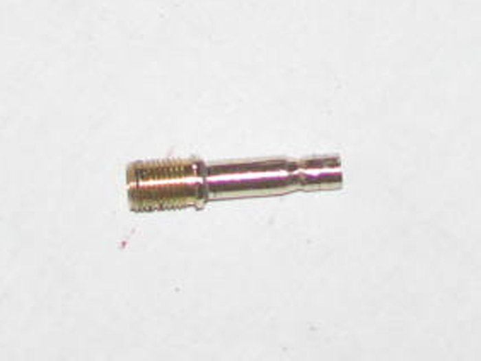
I also removed the threads.
I don't need them and it saves weight on top of the cylinder when installed.
The end that goes in to the plastic vent valve body has been shortened
to 2 layers of plastic so it does not stick in to the air camber channel.
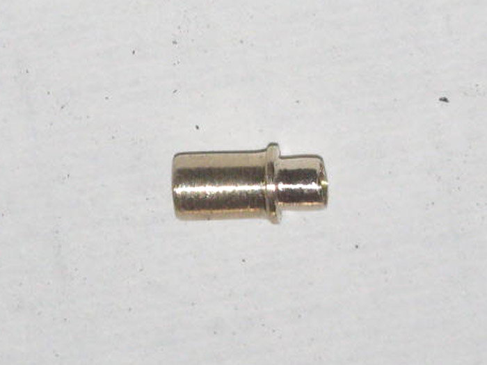
The Schreader valve body test fit in to the ballast tank vent valve
body.
The top part.
I have applied glue to the part and it is clamped in place while it
cures.
Brought the cylinder in the house.
Temperature outside dropped to mid 40s.
I though I heard rain starting which it is forecasted.
Stepped outside not to rain but hail.
I am done being outside today.
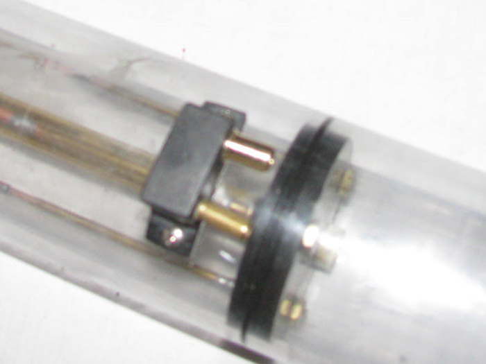
March 18th =================================================
A busy morning.
First thing I decided to test the ballast tank vent body.
Turned the cylinder upside down.
Plugged the 2 air vents on top of the cylinder. (photo above)
Filled the ballast tank with water through 1 of the flood holes.
Once it was full, I removed the plug on the new inlet.
Water began to drain out.
It appears to be slow.
I know air will escape faster but this is slow.
Plugged the inlet and unplugged the other inlet.
Just a little faster but slow.
Turned the cylinder over and drained the water through the flood holes.
Out to the shop.
I removed the vent valve body.
First thing I saw was the new inlet was partially covered with silicone
glue.
Cleaned off all the silicone on the vent valve body and the 2 brass
tubing.
I then blew through each tube using a fuel hose.
The air inlet tube was good but the new vent tube was restricted and
too slow.
Solution is to remove the tube and go back to the original vent valve
that I was going to make.
Reinstall the valve body without the new brass Schreader valve.
------------
Get the manifold parts out of the vise.
Looks good.
Sand all the sides smooth.
3 where close from sanding before assembly.
Check the air channels and clean if needed.
Make the side cover that will be glued in place after the brass tubing
lengths are determined.
This will happen when the air pumps are mounted to the rear electronics
tray.
Set to the side for later.
-----------
Going back to the end cap.
Time to drill several holes in the end cap.
I started with mounting the gear box on the back of the end cap.
The gear box needed to be in place to locate where the control rod
supports and bushing would be place.
I wanted 1/8" clearance from the brass tube to the gear box frame.
The shaft cup seal recess is cut in to the cap.
The depth of the cut keeps the cup seal above the end cap by about
1/32".
When the cup in the recess, the gear box will apply a little pressure
on the cup edge squeezing the cup to completely fill the recess.
With that done, I setup the drill press using a couple of guides clamped
to the table so I could not drill in to the o-ring groove. (again)
The end cap could be rotated and keep the same distance from the edge
of the cap to the hole locations.
This important because I have to not drill in to the o-ring groove
and the control rods have to have clearance away from the motor housing.
Motor is brushless and the outside case spin when running.
I beveled both side of each hole.
The drilled hole is also slightly over sized of the tubing.
This allows room for the glue to expand and produce a good seal a round
the tubing.
There are 2 brass tubes missing.
The air inlet and outlet.
They will go between the 3 control rod guides.
There is enough room to put the rubber boots on the 3 control rods
and the air hose on the 2 - 1/8" brass tubing.
The brass air tubes with go in to the cylinder and past the motor so
the air hoses can not fall on to the motor case.
Here the control rod tubes have the glue applied and will cure over
night. 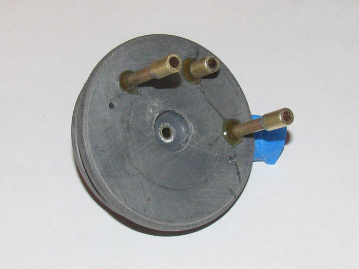
I have cut some plastic pieces to make 2 or 3 vent control rod guide
supports.
These will be mounted on top of the cylinder so the control rod can
go from the rear of the end cap to the vent valve body at eh rear of the
ballast tank.
The parts are in the vise to cure under pressure.
I should get those finished tomorrow.
Maybe even mounted on the cylinder.
Next project is to make the end that will go on the vent control rod.
It has to be removable and it will need to have a seal material on
it that will stay on.
I am thinking a wheel collar with 3 small holes drilled in the side
and one side tapered in to a slight cone.
Then make a form to pour silicone in and place the wheel collar on
it.
The silicone will go in to the 3 holes and the form will make the silicone
tapered.
Sort of like a carburetor needle valve.
March 18th =================================================
End Cap has been cleaned up after the glue cured.
The control rod through tubes have been cleaned out of glue that squeezes
in under the tape.
Set aside.
The reason for setting the end cap aside is, I need 1 stainless bolt.
The hardware store where I get these very small stainless bolts is
closed until further notice.
So no bolts for now.
Made 2 brackets to hold the push rod from the rear of the end cap to
the vent valve body.
I have made it for 1/16" rod but left enough room for 3/32" tubing.
Not sure the 1/16" rod will not bend under operations.
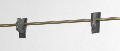
Next is to make the safety tank.
The tank on the right of this drawing.
The tank has a float inside with a seal material to block water from
exiting the top of the tank.
It has an outlet for air at the bottom.
Should water back in to the air hose while submerged, the float is
to stop the water from getting in to the water tight cylinder.
I have seen only one in a boat and it seems to do the job it was designed
for.
So I am going to give it a try.
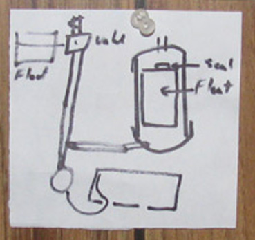
The tank will be brass tube and the end caps will be plastic.
There is no real pressure on the tank so I think gluing the end caps
on after I get the tubes and check valve installed in the caps will do
it.
The end caps are in the vise after some shaping and drilling the hole
in the middle.
There will be more shaping after the parts cure.
The float is a piece of foam with a seal material on the top end.
I have a couple of ideas to try before assembling the unit.
It all has to do with where in the boat I put it in relationship to
the air pumps.
The tank will be made so the end caps can be removed for maintenance
or repairs.
Here are the major parts of the unit.
There is no seal material on the float.
On the left side you can see the end of a 1/8" brass rod to give the
float weight to pull away from the vent seal hole.
The length of the float has not been determined.
I can test this in a bowl of water once I make the end caps for the
unit.
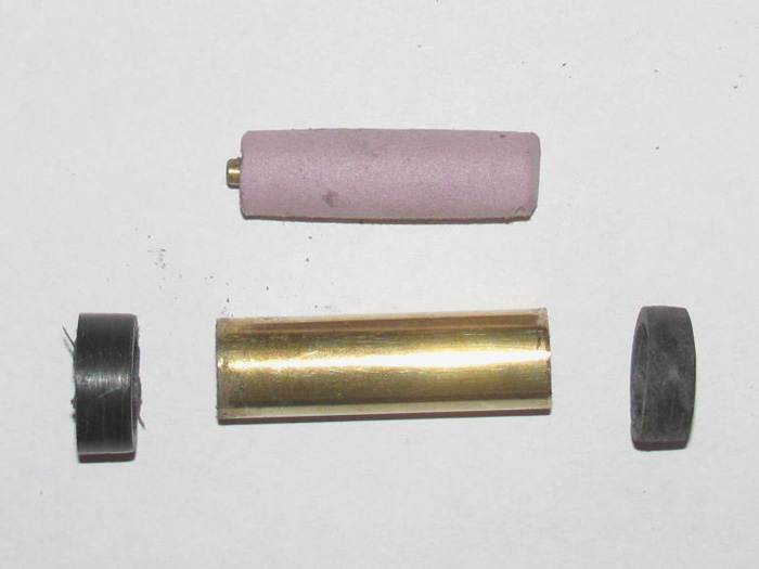
The black rings are the sides of the end caps.
When I make the end covers they will be cemented to the rings.
One end cover will have a hole in the center for inlet/outlet of air
in the cylinder.
The other end will have an inlet/outlet for air from the air pump.
Size reference.
The brass tubing is 1/2" diameter.
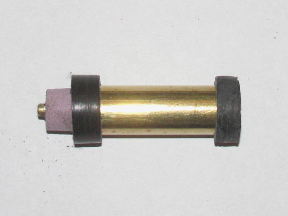
March 22nd ===============================================
Started by working on the end caps for the safety tank.
Did the shaping and I installed the 1/8" brass vent tube in the top
cap.
The bottom cap will have a 1/8" brass tube going across the bottom of
the tank.
This way, I have an inlet and outlet for the air.
This tube will pass through the bottom cap and will have a 3/32" hole
drilled in it that will access the safety tank at the bottom.
The inside of the cap is beveled so the water if any will drain to
the hole in the air tube and be sucked out during the ballast tank blowing
operations.
Moved on to the Rear cylinder end cap.
Drilled the last 2 holes for the air inlet and outlets.
Got the length needed for the 5/32" brass tubes.
I wanted a little bit bigger than the 1/8" brass tube for a tighter
fit of the fuel air hose.
The electronics tray has been shortened at the end cap end by 3/8".
The electronics tray has been narrowed by 1/8" on one side and by 1/16"
on the other.
Basically I cut the rolled over edges that I used to stiffen the aluminum
plate.
Turns out the aluminum plate is stiff enough on it's own.
It was flimsy before adding the motor bracket and the 2 servos.
They stiffened up the plate without the rolled edge.
I moved the servos in towards the center of the plate by about 1/16".
The servos are not touching by a thick piece of paper.
This allowed me to use straight control push rods in stead of having
2 bends in each rod.
A cleaner installation.
The 2 air tubes are now installed and it's that time where I have to
let the glue cure before continuing.
Rear of end cap.
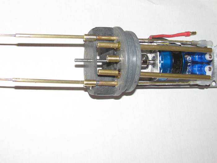
Front of end cap.
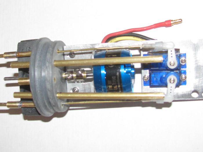
The 2 air tubes look like they are angled.
They are the same distance apart at the end cap and the end over the
servos.
The length was determined by having room to access the servo screws
without interference.
March 24th ===============================================
Looks like today is going to be laundry day.
The washer is out in the shop, so I may get some thing done today.
Will report any progress.
Now a little progress.
Worked on the air pump and manifold assembly.
Added the 2 brass inlet and outlet tubes.
Here is the assembly from the top.
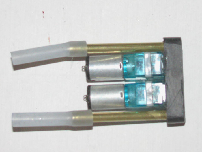
Assembly from the side.
The inlet and outlet tubes are angled.
Next photo will explain why.
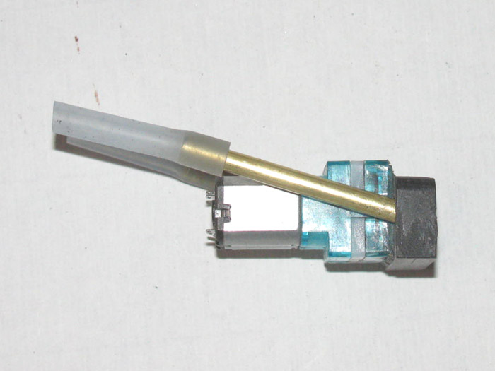
The tubes are angled to go over the rudder and stern plane servos and
control rods.

Top view.
The vent servo will be to the right of the air pumps.
The control rod will go over the air pumps, servos and motor case.
In the photo the control rod goes between the air tubes.
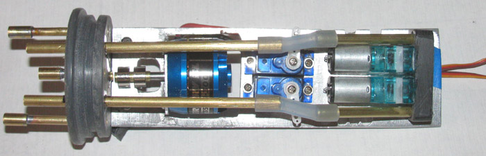
I need to locate where the Rx and speed controller will go.
It looks like they will fit on the under side of the electronics tray
if I make an tray extension with a drop in it.
Maybe not.
The issue to over come is the 8.5" maximum length from end cap to ballast
tank frame.
March 25th ===============================================
Today started with cementing the air pump manifold cover on.
It is currently in the vise to put pressure on the plastic as it cures.
Now to test fit the equipment on to the electronics tray.
Setup the electronics tray on the work bench so it sits level and I
can slide the cylinder over the tray as I place the equipment on the tray.
I have an 8.5" limit on the tray from the end cap to the ballast tank
frame.
The plan was to put the air pumps on the top of the tray.
So I put the Rx on the under side under the air pumps.
Looks good but the cylinder will not slide in place.
The Rx fits but I will not be able to plug in any of the equipment
plugs.
This will not do.
I have to keep in mind that I need to get 2 micro switch in there for
the pump off/on behind the ballast vent servo.
Okay, will the Rx work on top of the tray?
Yes but can I get the air pumps under the tray?
Until the pump bracket cures, I can not test it.
It looks like it should.
The air hoses can go down from the inlet/outlet brass tubes down to
the under side to the pumps inlet/outlet tubes by placing 1 hose down the
outside right and then 1 hose down the outside left if I notch the tray.
Happens there are already holes that power wires entered through before
that can be turned in to notches for the air hoses.
It looks like I might get it to work.
This will leave room for the ballast tank vent servo between the Rx
and the 2 servos for the rudder and rear planes.
There looks like there m ay even be room for the 2 micro off/on switches.
Better yet, by putting the Rx on top, I can move it forward a 1/2".
There will be plenty of room to plug everything in and not have to
smash the wires over to fit.
So, I am waiting for the plastic cement to cure.
I will have to make some plastic blocks to use as mounting blocks.
Or I can do as I have on other projects . . . silicone glue the equipment
in place.
----------------------------
Test fitting says, I can not get the Rx on the top of the tray.
And the Rx did not fit under the tray with out lifting it up.
A closer look showed me that the Pitch control which was mounted originally
on the side of the Rx made the Rx and pitch controller too wide and did
not fit down in the cylinder curve enough.
So I took the pitch controller off the Rx.
Now there is plenty of room. (hoping)
Above the cylinder is the servo that is needed to operate the ballast
tank system.
Below the cylinder is the speed controller that will fit on the the
underside of the tray behind the rudder and rear planes servos.
Before I install the Rx and speed controller, I need to make the bracket
for the 2 micro switches that will operate the air pumps.
2 switches because I would like a two stage air pump system.
Mid servo I get 1 pump and full servo I get 2 pumps.
If there is not enough room, then 1 switch it will be.
This is a trial and error installation.
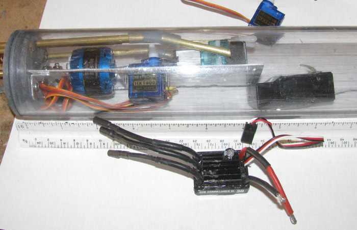
March 26th ===============================================
In the shop this morning.
It's cold and I fired up the heater.
I sat down on my wooden milk crate (no chairs in my shop) and started
test fitting the equipment that needs to be put on the rear electronics
tray.
Yesterday, I had a set back.
I just couldn't get the parts to fit but it was because they kept sliding
off as I tried to put other parts on.
So today, I gathered up several small clamps and a roll of tape.
Nothing is going to slide this time.
My main issue is the Rx.
It is a Futaba 8 channel Rx and it is bigger than the other Rx I use.
I can put it almost any where but then I can not get to the servo plugs.
So clamp this there and that over there.
I am back to having the air pumps on top and the Rx underneath.
But there is just not enough room under the tray.
Yesterday, I took the Pitch Controller off the side of the Rx.
Today, the Rx fits under the tray and the tray is not being pushed
up.
I was going to cut the tray 1/4" shorter when I realized I was going
about this all wrong.
Instead of cutting the tray, I made a plastic tray extension of about
1.5".
This will sit under the original tray and bolt to it behind the air
pumps.
This came about because to put the ballast tank vent valve servo in
it needs to be lowered.
By putting the tray extension under the original tray, I get 1/16"
more room.
With the Rx under the tray and this plastic extension, I can mount the
ballast tank vent servo behind the air pumps with room for the 2 switches
I want to control the 2 motors.
Also by using plastic for the extension, I can cut with plastic pieces
to make the servo brackets and brackets for the 2 switches.
Then I can mount the air pump plastic manifold to the extension. (currently
curing in the vise after applying cement bond)
I have room for the speed controller on the under side of the tray between
the 2 servo bottoms and the Rx.
The issue I was having was the power to the motor wires.
They are thick and stiff.
And too long.
But I do not want to cut them because I do not have those kinds of
connectors.
I moved the wires this way and that trying to find a way to get them
in there.
Finally I found that if I turned the speed controller with the wires
going towards the motor, I had enough wire to route them from the motor
to the end cap, turn them and come back the other side.
It will take 2 tie wraps to hold them off the motor case but it will
work and it looks good.
The 2 ballast tank air pump motors with be operated individually with
each having its own switch.
I now have room to mount the switches side by side and the servo will
have a wheel color activator on it.
The wheel collar will have brass flat stock that will slide over the
switch arms.
The switches will be off set by 3/16".
This way 1 switch will activate before the other.
I get my 2 stage air pump system.
Nice easy blow or full on it's coming up.
Not a lot of time in the shop but I got a lot of problems solved.
Now its, "Just Build It!"
March 28th ===============================================
A bunch of plastic sheet scraps.
Pair scissors.
Time to start making mounting brackets for 2 switches and the servo.
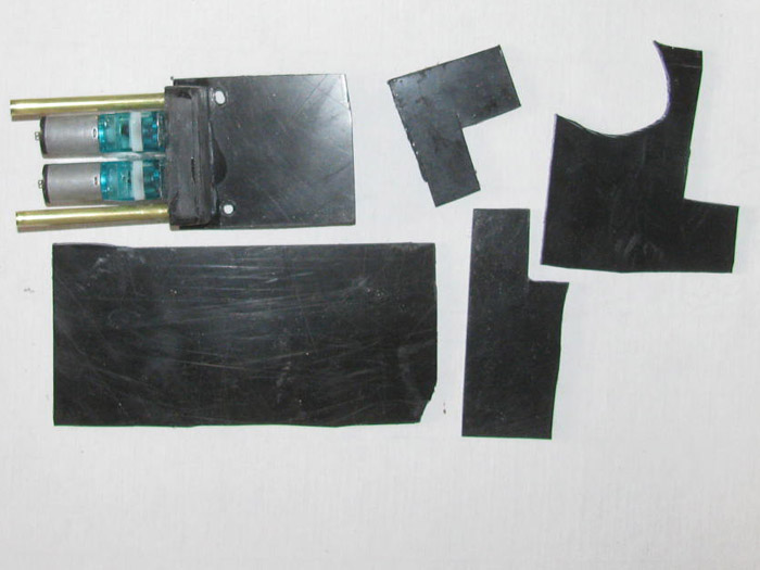
Made a guide for the long control rod from the end cap to the ballast
tank servo.
Made an "A" frame for the 2 switches. (still needs to be sized after
the cement cures)
Location for the servo has been established.
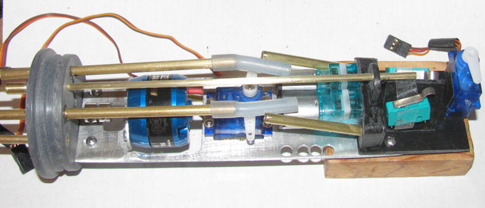
The switches are taped on to make sure I have the correct location.
The "A" frame is a little too tall but better tall than short.
The servo mounting brackets are in the vise curing.
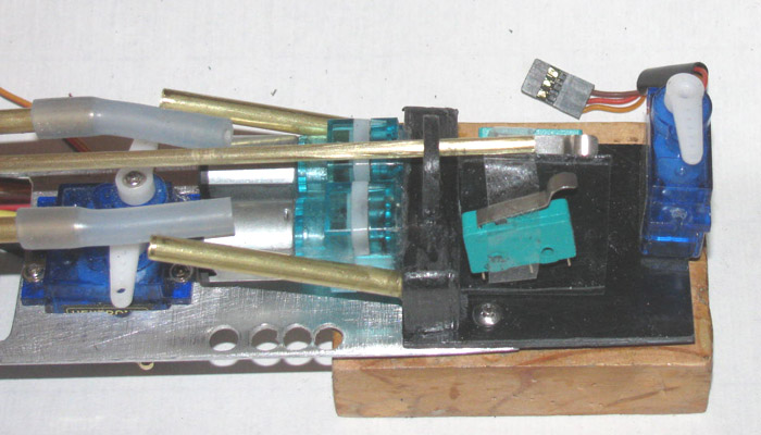
I checked my Rx plug list to make sure I have enough plugs for every
thing.
First look said I did not.
But a closer look shows channel 4 is empty so I can draw power from
there for the air pumps.
Will have to do a current test before I do that.
May have to make a voltage regulator to go from 7.4v to 4.2 volts.
March 28th continued =====================================
Back in the shop. I started assembling plastic parts.
Got the ballast tank vent servo mounted.
Took the electronics tray and the Rx and slid it all in to the test
cylinder.
Looks good then when I measured the overall length, the tray with equipment
is 3/16" too long.
The only thing sticking past the maximum length is the Rx.
It will not slide under the servo/ pump tray.
Well that is not good.
Cut the servo brackets off the plastic tray extension.
Did more measuring.
I have to get the Rx to move 3/16" in to the plastic extension tray.
It does not work as is so, just take the Dremel cutting wheel to the
aluminum tray and cut back to the air pump manifold and wide enough for
the Rx to slide between the plastic edges.
Left edge of the green switch in the photo above.
Next cut the plastic tray to match.
Tray cut and only needs cleanup.
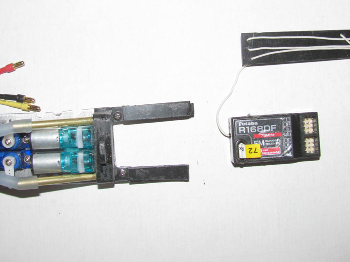
--------
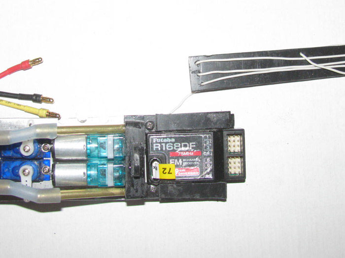
--------
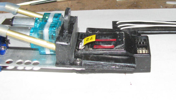
Test fit all fit in the cylinder.
Now it fits and I have about 3/16" clearance.
Now I have to figure out how to mount the servo.
It looks like it will work laying on it's side.
First I have to build up the extension tray to clear the Rx so I have
something to mount the servo brackets to.
Those parts have been cut and are in the table vise while the cement
cures.
I was making a bracket for the 2 switches but I stopped because the
new lay out may or may not work.
I think it will but until the new tray extension arms are re shaped
and the servo location finalized, I can not make the switch brackets.
So, I have things to do tomorrow.
Wiring comes next.
Should be straight forward.
Plug in 3 servos.
Power wires to speed controller.
Then test air pumps for draw and decide how to wire them.
Through a Rx plug or use a voltage regulator.
Or run the pumps in series and use only 1 switch.
So many options to figure out.
March 29th ===============================================
I am in the shop working but it is going slow.
Cutting and cementing plastic sheet parts.
I have built the half box that goes over the Rx.
Test fit in to the cylinder shows it will work with room to spare.
Now the ballast tank servo and 2 switches has become another issue.
I have made 3 mock up brackets only to find there is not enough room.
I may have to cut the mounting brackets off the servo to make it fit.
I got the Tx out and setup the Rx and the ballast tank servo to find
out which way the arm swings.
This determines which side the servo will go on.
Tested the switches to find out which 2 lugs will give me "on" when
depressed.
Back to the shop to see if I can get this puzzle to work.
-----------------
I made 2 plastic blocks that raise the switches up to the control rod.
All the parts are sitting in place temporarily to test fit.
It looks like the plastic switch block for the top switch will also
work as a mount for the servo.
There will be a wheel collar or 2 on the control rod to engage the switches.
This will give me the 1 or 2 switches activated individually.
Two stage air pumps.
The Rx fits under the tray with just the plug sockets exposed.
Tomorrow, I will be in town to pick up mail and the hardware store is
just 3 doors away.
I will pickup the needed stainless screws that will hold the switched
to the plastic blocks.
I need to screw the switched on the blocks before I can place the blocks
on the tray and cement in place.
Got to stop parts from moving around.
The servo is not in the correct position.
The horn will be more inline with the control rod.
But when I put it in place, the servo falls off the tray.
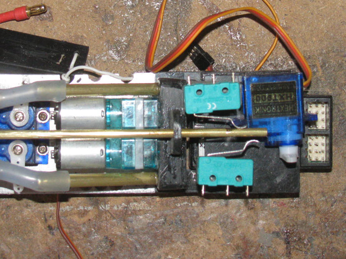
My electronics tray is 8.25" long and I have 8.5" of room.
Success!
I will make a new bracket for the antenna.
This one was to keep the wire out of the way while working.
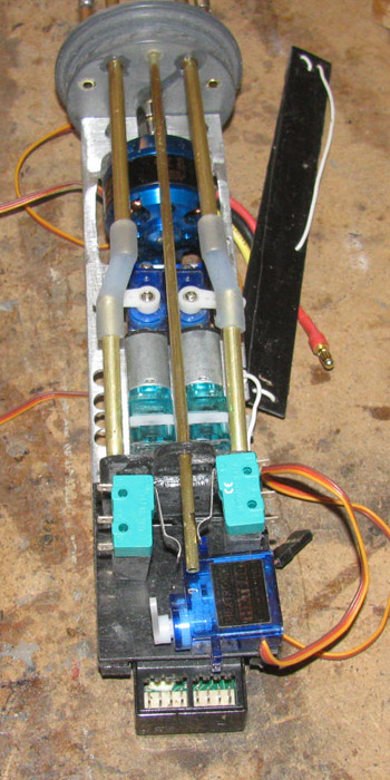
March 30th ===============================================
Got a late start this afternoon.
I did get some things one.
I got the small mounting bolts in town this morning.
I measured one side for 1 air pump switch.
Made a couple of adjustments with the control rod in place including
the wheel collars which will activate the switches.
Drilled the 2 holes in one of the plastic blocks.
Made a cut or two in the block to accept the servo end mounting tab.
Mounted the servo to make sure it was flat and above the tray.
With the control rod in place I cemented the plastic block with the
servo and switch installed.
This let me see where the wheel collar met the switch activator arm.
The wheel collar has to past the switch without touching the activation
arm until it get to the arms bump.
Held in place for 15 minutes while the cement set.
Let it set for 30 minutes before mounting the second switch block.
I had to file a notch in the block to allow it to go over the air pump
manifold about 1/8".
This was to get the 2 activation arms on the switches to stagger.
By staggering the activation arms, the wheel collars will push 1 without
pushing the other.
A little more input on the control rod causes both switches to be activated.
I got my two step switching devise.
Was thinking about the ballast tank vent valve.
It will be spring loaded closed.
The servo will pull it open.
What to use for a spring.
Took my favorite ball point pen a part to see if the spring would fit
over the control rod.
Looked like that is what it was made for.
But this is my favorite ball point pen.
Went looking for an old pen.
Out in the tool shed I found on up on the screw driver board.
Took it apart and there was the best looking spring I have seen in
a long time.
Looked at the printing on the side of the pen.
Turns out this pen is 42 years old. (no it doesn't write any more)
The spring will live on in my Gato, hopefully keeping it on the surface.
It amazes me how much time making small parts takes.
Especially when they have to be glued together and cured to move on.
Next, I think I will be making something to keep the Rx in place.
Whether it's a tie wrap or some sort of plastic or aluminum spring
clip.
March 31st ===============================================
I have been working on the control rod linkage.
I have gotten the length of the connection from the servo to the control
rod, set.
There are 2 wheel collars in between the 2 switches.
The control on the Tx is set to center.
The vent valve is closed and the 2 switches are off.
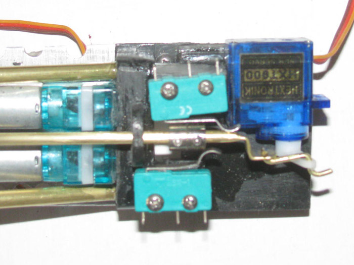
The servo has been moved to full vent of the ballast tank.
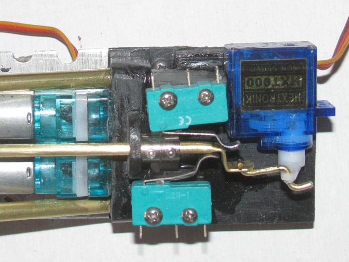
The control rod has been moved to the first pump switch. (bottom switch
is on)
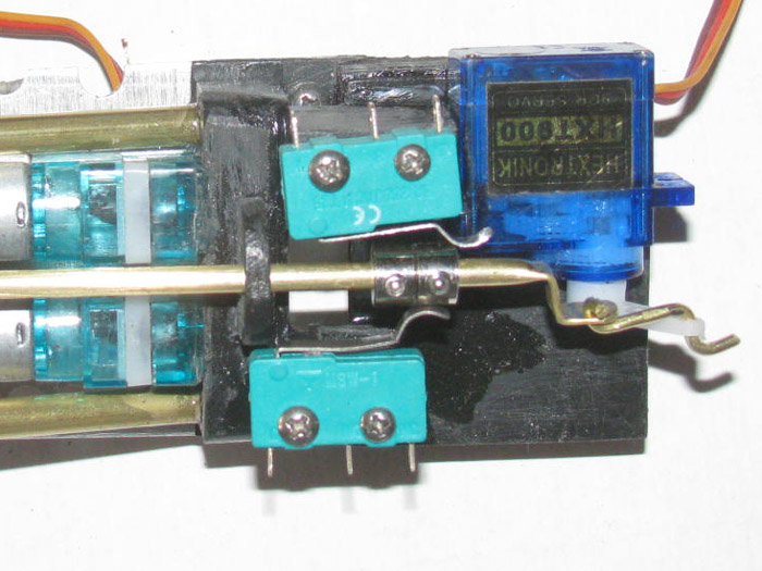
The control rod has been moved to activate both switches. (both switches
are on)
I have a two stage air pump system.
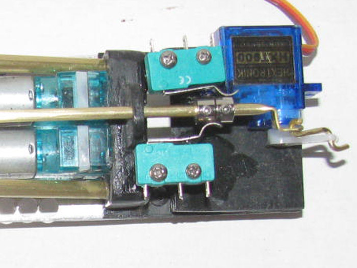
Looking from the right side.
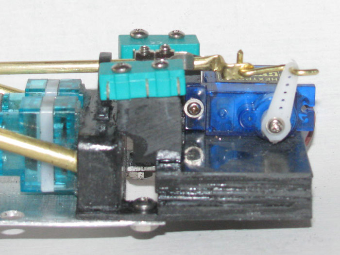
All control rod movement was done with the Tx and Rx on.
Checked the electric poles of the pump motors.
Checked the amps needed for each motor and in combination.
(looks like I can use the Rx as the power source)
I have an empty Rx plug socket. Access to power)
Found a short servo wire that had been cut off a bad servo.
The plug is good and the wires are long enough.
Cut the white wire from the plug.
Only need the Red and Black wires.
Run the Red wire from the servo plug to the center lug of both switches.
Check switches to make sure which lugs are the normally off. (got it)
Run a Red wire from switch #2 to the air pump on the same side
of the tray (top).
Run a Red wire from switch #1 to the air pump on the same side of the
tray. (bottom)
The order of soldering was because the #2 switch was up when I went
to solder.
The black wire on the servo plug was not cut so I could run the wire
as a single piece.
Opened up the insulation in the middle of the wire at the motor connection.
Cut the wire to reach the other motor.
Soldered the center cut first then the end to the motor lugs.
Checked the wires for continuity with the multi meter.
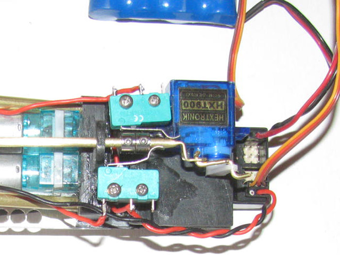
April 1st ===============================================
I started today by looking for my bag of nylon clevis.
While looking through the parts box, I had to move the servo wires
and other big packaged things.
I also had to move the bundle of Velcro strap.
Wait. . . . .!
In stead of trying to make some sort of bracket out of plastic or aluminum,
why not use the Velcro?
Okay here is what I did.
The Velcro strap is 3/4" wide and I cut 2 pieces 1/4" of loops and
hooks.
To make sure I could move the Rx to fit the space, I put 1 piece of
Velcro on the electronics tray long wise.
The piece of Velcro on the Rx went side way on the top.
This will give me about 1/2" I can move the Rx forward and aft.
Will see how it fits in the cylinder after the silicone glue cures.
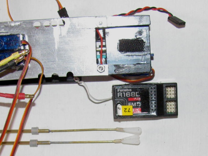
Back to the clevis.
I needed to shorten my original control rods 3/4".
This was due to the shortening of the electronics tray between the
end cap and main motor.
I do need to make new small bends in the rods to make sure they do
not touch the motor casing.
I did test the Rx, the rudder servo, rear planes servo and the ballast
system servo.
Did a little adjusting on the ballast servo.
I wanted more neutral center than I had. (too close to pump switch)
I though about grinding the wheel collars a little thinner.
Then I though why not try adjusting the Tx percentages of throw.
(my main Tx does not have computer adjustable controls so I
was slow to think about this Tx which is fully computerized)
Centered the control knob.
Moved the wheel collars back away from the switch about 1/16".
Moved the control know to the full 2 switches on position.
The control was set at 60% so I added 10% which moved the wheel collars
to center of the switch.
Slowly moved the control knob to activate the ballast tank vent.
Spotted and adjusted the percentage down to 25%.
This was to keep the wheel collars from hitting the rod guide.
Move the control knob to full vent.
The wheel collars where short of hitting the guide.
Slowly adjusted the percentage until the wheel collar just touch the
guide.
Time to test full control movement.
Center knob to the mark.
Clearance from switch is still 1/16".
Move knob to full vent.
Wheel collar touches guide but there is no pressure on the guide.
Move the control knob to first pump switch.
Turns on. . Good.
Move control knob to full for both pumps.
Second pump comes on and wheel collar is center of the switch.
. . GOOD!
Rudder and rear planes servo work fine.
-------------------
I still have the speed control to mount and the pitch controller.
I have places for them, the issue is routing the wires.
Then route all the servo wires and main power.
April 2nd ===============================================
Testing the Rx Velcro mount.
Placed the Rx in to the recess.
Pushed the Rx back against the tray.
Pushed the Rx down on to the Velcro.
Holding well.
Turned the tray over and started plugging in servos.
Okay, what's this.
The Rx moves up and down as I plug in the servos.
Turns out the Velcro is making a 3/32" gap from the Rx to the tray.
The 1/4" wide Velcro is letting the Rx rock from end to end.
This will not do. ;^(
The Velcro pieces are removed with an Exacto knife.
Find the thin aluminum sheet I bought a couple of weeks ago.
Measured the Rx and the tray for an aluminum bracket.
Cut it. (this aluminum sheet is so thin, I cut it with heavy scissors)
Make some marks showing the Rx width.
Place in table vise and using a wooden block, I bent the aluminum strip
in 2 places making a bracket that fits over the Rx and in to the tray recess.
This is what I got.
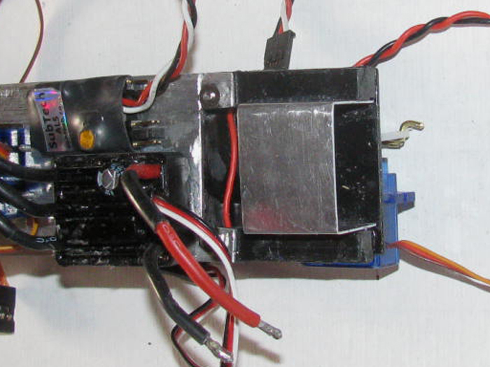
Cleaned up the aluminum to get the oil stuff off of it.
A couple of small drops of silicone glue and put the bracket in to
the tray recess.
The pitch controller is sitting in place but not fixed there, yet.
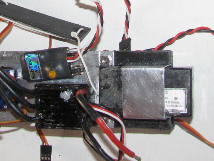
Put the Rx in to the bracket and turned the tray over to look at it
from the top.
This shows access to the Rx plugs.
Plenty of room.
I measured the overall length of the tray from the end cap to the end
of the Rx.
I have a full 1/4" clearance to the ballast tank frame.
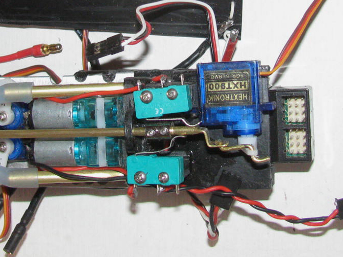
------------
I had a few minutes.
When out in to the shop to check on the silicone curing.
Not 100% but every thing is solid.
Started running servo wires.
I checked each one with the Tx as I went to make sure I was connecting
the correct servo to the correct channel.
It wasn't long before I had everything hooked up on the rear electronics
tray and working.
Rear Tray (complete)
1. Rudder
2. Rear Planes with Pitch Controller (adjusted)
3. Throttle
4. empty
7. Ballast Vent & Air Pumps (adjusted)
Front Tray (assembled but no wires to rear tray)
5. Bow Retract
6. Bow Planes
8. empty
Power Switch
Assembling the equipment in the cylinder is next.
This is when I will connect the main power (soldered) and 2 servos
from the front the front tray to the rear tray through the brass tube between
the 2 ballast tank frames.
I made a special tool just for pulling the wires through this tube.
30" of piano wire with a squared off hook on the end to hold the servo
plug.
Almost time to plan water testing again.
April 3rd ===============================================
Making small parts is so time consuming.
Once made they need to be glued together which take a lot of waiting
time.
Today's project is the ballast tank vent valve seal.
It has to be detachable from the end of the control rod.
It has to hold a 1/8" ID o-ring.
It has to not pull off when the control rod pulls away from the vent
valve body.
Starting with a 1/16" brass long control rod.
Next a brass tube that slips over tight.
after that another brass tube to slight tight over that.
What I am making is a part that goes from 1/6" ID to 1/8" ID.
Took 3 parts.
Then I made 2 plastic parts to slip over the 1/8" tube that will be
turned round at about 3/8"+.
This will be the set for the o-ring to be pushed against the valve
body.
The end of the rod and 2 brass tubes will be tapered to a point then
flatten off a little.
This will be a guide in to the valve body so the control rod with it's
o-ring seal center in to the valve body vent hole.
The brass tubes slip over the 1/16" rod.
There is a wheel collar that slips over the 1/16" rod that has the
brass tubes soldered to the wheel collar.
This allows me to remove the seal of the 1/16" rod.
This is required to remove the control rod from the 2 plastic guides
on top of the cylinder.
Once I get all the parts made, I will take photos of them disassembled
and then as I assemble the unit.
I think I need to make a brass ring from tubing that goes over the 1/8"
tube that will hold the o-ring on.
April 4th ===============================================
Turned the air manifold vent seal valve.
Here is the ballast tank vent valve system unit parts.
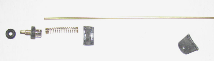
Parts assembled.
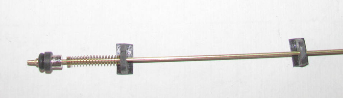
Assembly sitting on top of the cylinder.
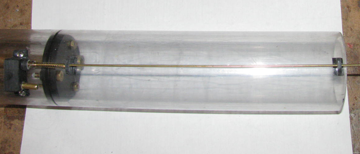
When installed, the spring will have some compression to it.
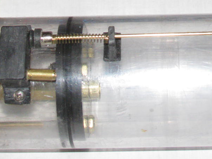
While I am in the shop.
I thought I would put some colors on the boat.
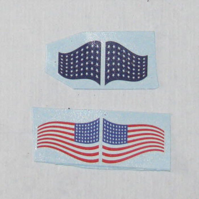
Bow Jack.
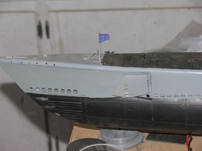
Stern colors.
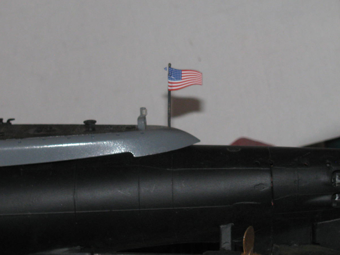
After the water completely dries, I will paint with clear.
April 5th ===============================================
Time to installing the electronics tray in to the cylinder.
#&%* That did not go well.
Made it past the ballast tank servo and hit the switch lugs.
I missed the measurements by 3/16".
Okay, I won't dwell on it.
How do I fix it?
Originally I was going to put the switch on an "A" to slant the switches.
But my A piece was not going very well.
So I made blocks of plastic to mount the switches on top.
Forgot about the clearance when I did that.
In the photo you can see the block under the switch.
This is where the error on my part happened.
I removed the switches and the control rod so I could get to the top
of the plastic blocks.
Calmly and slowly, I took my Dremel with a thin grinding blade and
I cut the top off the plastic blocks at an angle.
Carefully checking that the switch activator arm would connect with
the control rod.
OOPS. One was cut too short and needed to have plastic pieces added
back on.
3 layers. I just happen to have a 3 layer pieces sitting right here.
It was a cut off end of another piece I made.
The piece has been cemented on top the block and is curing.
So what next?
I will mount the ballast tank vent rod guides on top of the cylinder.
Measured the spring compression and the location of both guides.
I used blue tape to surround the guide base.
Sanded the area inside the tape.
Applied silicone and placed the two guides.
Put the control rod in the guides to line the vent valve seal over
the vent manifold hole.
Used a flashlight to see and make sure I got it centered .
It has been set aside to cure.
---------------------------------------
Reshaped the servo mounting blocks.
Installed servos.
Adjusted control rod so everything works as planned.
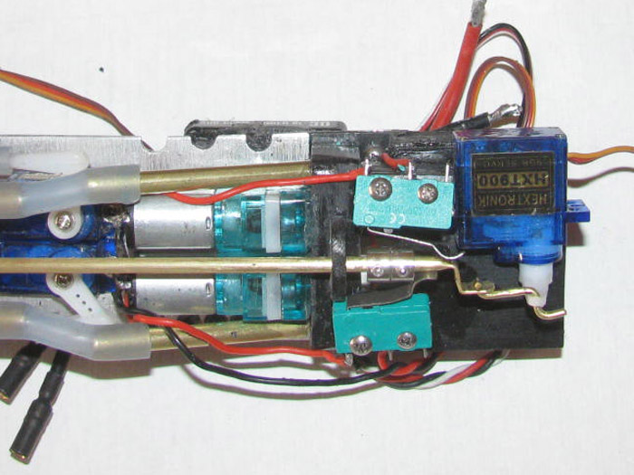
Test fit in to cylinder.
Like always. . . fix 1 problem only to find another.
The speed controller hits the cylinder with it's cooling fins.
The fix is to move it towards the center of the electronics tray.
To do this, I have to remove the pitch controller.
Sure glad I use silicone to mount parts.
Pitch controller removed.
Test fit the electronics tray in to the cylinder.
There is is in the cylinder.
But the pitch controller is not there.
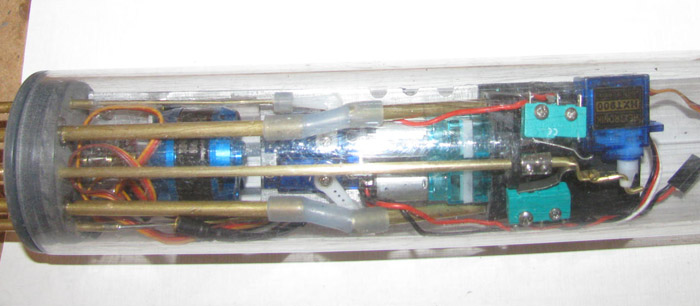
Now I have to find a place to put the pitch controller.
A quick look say this is not going to be easy.
So, I think I am finished for today.
-----------
I have been thinking about the pitch controller and where to put it.
There just isn't any room with the way the parts are installed.
I will have to look closer but I was thinking if I put the switches
on more of an angle, I might be able to get room on the right side. (bottom
of above photo)
All I can do is make a couple of new parts and try it.
April 7th ===============================================
Today so far has not produces much in the way of gains.
Started by clear coating the 2 flags.
That did not go well at all.
The front union jack is so fragile that applying paint caused the decal
to disintegrate.
Tried to lightly spray the rear flag.
It was going good but then as the paint dried, the flag curled up and
feel apart when I tried to straighten it.
My observations say that these decal flags might work for a display
model but even if I could have clear coated the flags, in the water they
would have been destroyed.
--------------------
I moved on to finding a place for the pitch controller.
There are places that it will fit but would not allow for the length
of the servo plugs.
I have trimmed the shrink tube on the end of the pitch controller board
to make it 1/16 shorter.
I might be able to put it next to the ballast tank servo.
I will have to make a bracket so it can be removed to get to the servo
horn screw and mounting screw.
I will make it fit.
I even looked at putting it between the rudder and rear planes control
rods.
I have to make sure the ballast tank control rod that will go over
the pitch controller does not touch.
It is only one possible placement.
---------------------
Oh, I did a pressure test on the new ballast tank vent valve assembly.
I covered 2 of the ballast tank flood holes with tape
I put a finger over the air inlet on top of the tank.
I moved the spring loaded vent valve to let it seat on it's own.
I blew in to the open flood hole.
I blew hard enough to lift my finder off the air inlet tube.
This was amazing.
I have not yet applied silicone grease to the o-ring seal.
This was a success.
I needed it because all the other stuff has been come frustrating.
April 9th ===============================================
No work was done on the 8th.
I was at the VA getting 3 more surgeries done on my face.
Nothing life threatening.
I did go through 2 virus checks and tests.
Right now I looked like I went through a glass window.
Today, I am in the shop.
After reshaping the switch mounting blocks, I have managed to get the
room needed for the pitch controller.
The photo shows the switch mounting blocks before I angled them even
more.
This gave me a place to put the pitch controller.
I am making a plastic clip that will hold the pitch controller with
a small length of tape.
It will be below the servo horn and to the right of the lower switch.
It will be at about 45 degrees on the tray.
The pitch controller can be removed by taking the tape off.
This will give access to the servo horn screw and servo mounting screw.
I tested this by taping the pitch controller on the tray and sliding
it all in to the cylinder.
Tom, I got the 10 pounds in to the 5 pound space.
I do need to test the pitch controller in place at the angle to make
sure it responds correctly.
The instruction on the pitch controller says it can be mounted flat
or on edge as long as it is facing front to back by the pins.
So why would it not work at an angle if facing the right direction?
I will know in a few minutes.
I can test it by itself not on the tray.
Just plug in the pitch controller to the Rx and a servo in to the pitch
controller.
-------------------------
Results of testing pitch controller. (good)
Seems the pitch controller does not care which way it sits as long as
the fore and aft axis is right.
I put the pitch controller on the table flat, then on edge, then I slowly
turned the pitch controller around it's fore and aft axis.
No matter how it was turned, it gave the same input to the servo.
I am good to go on the installation.
Once the plastic cement cures on 2 parts.
It has been raining for 5 days now.
Today yesterday it started getting cold.
I ran in to a little snow coming home yesterday from the hospital.
Today, even with the heater on, it is still cold in the shop.
After an hour, the temperature is only up to 50 degrees.
With my face all stitched up, I can not afford to catch a cold or worse.
So, I am going to leave the plastic parts in the vise over night and
try to stay warm the rest of the day.
----------------------------------
Plastic bracket installed on tray.
Pitch controller shown below tray.
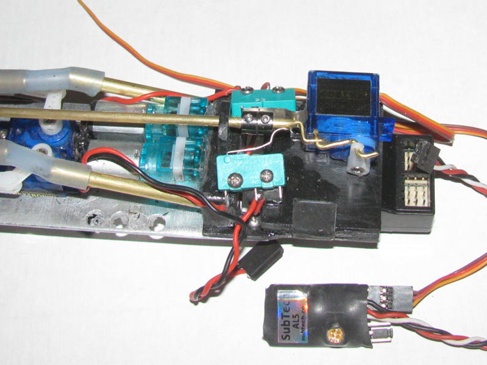
The pitch controller set in place but not taped.
There is a bracket behind the pitch controller to keep it away from
the servo arm and linkage.
Cement has not cured.
There is room to plug in all the stuff in to the Rx without hitting
the pitch controller and keeping the 8.5" over all length.
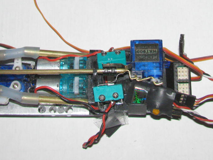
April 11th ===============================================
The river between the house and the shop caused by all this rain has
kept me from the shop.
Was thinking about building a bigger boat!
I thought I would see about mounting the speed control for the main
motor.
I did 2 test fits routing the wires differently to see which way would
work the best.
Cleaned the electronics aluminum plate. (sanded to make sure all the
old silicone glue was gone and any oil from handling.
Sanded the back of the speed controller again.
Wiped clean.
Apply a couple of small drops of silicone glue on the back of the speed
controller.
Set it in place on the tray.
Clamped it with a small C clamp.
Of course it moved and had to be readjusted in to place.
I found that the 2 air inlets with the hose on, touched the cylinder
wall and change the angle of the tray.
Took the pump section off the tray so I could get to the tubes to bend
them down and inward.
This moved the hosed away from the cylinder wall.
In the process, I dislodges 1 of the air pumps.
Cleaned them of all glue and reglued in place.
(this may later require a stronger glue but for now, I am using silicone
glue so I can remove them from the manifold if necessary)
So the speed controller is curing.
The air pump is curing.
And another piece of plastic to hold the pitch controller has been
added and is curing.
This should be the end of building stuff on the rear tray.
Reassemble in the cylinder will be next.
April 12th ===============================================
I will be staying home today.
Might as well go out to the shop.
I think I will dig through my 2 or 3 parts boxes and see if I can find
2 small power plugs.
Both ends.
Was thinking about assembling the cylinder and remembering I have to
solder the power wires at both end after going through the brass tube through
the ballast tank.
Why not put plugs on each end so I can disconnect the front and rear
tray without having to get out the soldering iron?
Such a simple concept.
I am finished changing the ballast tank length so why not leave the
power wire in the brass tube.
I don't know. . . Why not?
The sun is coming up.
Should warm up in the shop in a couple of hours.
After digging through 2 boxes of parts, I found a bag of power plugs.
Soldered plugs to main power wires.'
Soldered other ends to main speed controller and to the switch at the
front to turn main power on and off.
Now I can test the everything on the bench out of the cylinder.
The plug on the rear tray will plug in to the plug at the front tray
where the batteries are.
Testing is on boat batteries and not the temporary battery.
Mounted the propeller gear box on to the rear end cap.
I did remember to grease the cup seal before mounting the gear box.
The seal is between the gear box and end cap.
I did have to re adjust the motor bracket.
This was modified during this project.
Motor was laboring to turn.
I loosened some mounting screws and tightened them trying to keep the
motor turning freely.
Took a while, there are 6 screws and bolts that hold and can be adjusted.
It is not perfect yet but the motor turns without binding now.
Plugged in the rudder servo. Test good.
Plugged in the rear planes servo in to the pitch controller and then
the pitch controller in to the Rx. Test good.
Plugged in the ballast tank vent/air pump servo. Servo test good.
Plugged in the air pump power wires to Rx. Test good.
I did re adjust the wheel collars to get the neutral position to have
more neutral area.
That is every thing in the on the rear electronics tray.
Next will be putting the electronics trays in to the cylinder.
An issue may come up.
I have very little silicone grease left.
I don't understand, I bought this 2 oz jar in 1973 for an underwater
camera case I was using at the time.
I did some looking and the hardware stores have a 2 oz tube of silicone
grease.
Reading the spec, it sounds like the same stuff I have been using.
May get some tomorrow.
I will check it out and if it is the same, then I will squeeze it in
to my little jar.
I think I may be done for today.
While soldering this morning, the smoke from the flux seem to bother
me.
Might be all the drugs I am taking from this last weeks surgeries.
(3 on face)
Not to worry, all is good.
April 13th ===============================================
Not much time in the shop.
What to build?
I need a fitting that will mount on the ballast tank vent control rod
that will activate the vent open.
The same rod activates the 2 switches for the air pumps.
The control rod comes out of the cylinder near the top of the end cap.
The vent valve control rod comes back to the end cap at about 3/8"
above the cylinder.
Not a problem.
I will make a plastic part that will fit on to the control rod coming
through the end cap and will slide on the vent valve control rod.
When the the servo moved to pump air, the plastic part will slide forward
not moving the vent control rod.
I may add an stop and a spring that will allow this part to put more
pressure on the vent valve seal during air pumping.
When in neutral, the spring may have a little pressure on the seal.
When the servo is moved to open the vent valve, the vent valve control
rod will move back away from the valve manifold and put pressure on the
spring as the vent seal moved away from the manifold.
This will be much easier to explain once I make the parts and install
them.
It is a rather simple system.
The plastic parts are cemented together and clamped in the vise.
Again, I wait for the parts to cure.
April 14th ================================================
More work on the vent valve connection arm.
This is slow.
It is made up of
6 pieces of sheet plastic 1/16" thick.
1 - 1/8" wheel collar.
5 small slivers of sheet plastic to go around one half of the wheel
collar.
Each piece requires plastic cement and cure time before I can go to
the next piece.
Getting close to shaping the part.
So while it cures, I moved on to the Rx antenna.
It has been in the way every time I work on the electronics tray.
It is worse than all the servo wires hanging loose.
So it is time to make the brackets to hold the antenna in the cylinder
and out of the way.
Small pieces of sheet plastic have been made and assembled.
A single servo mounting screw to attach the end cap bracket.
The other bracket is cemented to the air manifold.
Mounted the brackets.
Strung the antenna wire making sure it does not touch anything.
Here is the antenna on the rear electronics tray.
A single small drop of CA glue at the end of the antenna on to the
plastic Rx bracket holds it in place.
(far right is the end of the antenna)
(all my boats have internal antennas)
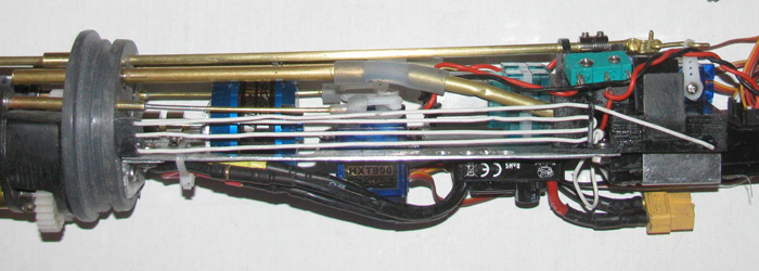
----------
April 15th ================================================
Installing the rear electronics tray in to the cylinder.
I bundled the servo wires and power wires.
Measured the tray overall length and the length in the cylinder to
the ballast tank frame.
1/16" is not going to be enough.
A quick look at the ballast tank frames showed me I could move the
ballast tank frames forward about 1/4" before hitting the bolts holding
the vent valve manifold on the cylinder.
Place the cylinder on end on the floor.
Using a lone half round file (what was handy) I put the end of the
file on the ballast tank frame.
A slight tap and both frames moved forward.
Looked at how much the frames slid.
Did another tap and the frames move again.
Not quite touching the 2 manifold bolts.
Measured the gain and found I got a full 3/8".
The problem is the 2 servo wires and the power wires coming from the
bow to the rear though the brass tube are right in line with the Rx.
Now there is room for the wires will bend and miss the Rx.
Slid the rear electronics tray in to the cylinder.
Was good until it got to the speed controller.
Looking I can not see the problem.
Maybe the power wires may be binding the speed controller to the cylinder
wall.
Easy enough to know exactly.
Pull the speed controller off the tray.
The tray slid in past the speed controller location but then stopped
near the switched.
Again looking for what ever is binding.
Found it.
Sort of silly.
The 2 wheel collars used to active the switches are binding because
the set screws are sticking out of the wheel collars and hitting the cylinder
wall.
Pull the tray out and turn the wheel collars so the set screw are pointing
down between the switches.
Slid the tray in to the cylinder.
It drops in all the way to the end cap with no binding and no pushing.
Dropped in on its own weight.
Now I need to figure out how to get the speed controller in so it does
not hit the cylinder.
It was the cooling fins that hit.
Now that the tray is in the cylinder, I can measure and mark the vent
valve actuator arm.
I did measure the through cap tube for the control rod and cut the
excess control rod length.
With the boot seal on the control rod and using the Tx and Rx, I got
the full movement of the control rod.
Back to the shop to figure out the speed controller clearance issue.
Working on the vent/blow system.
The plastic piece on the control rod has a wheel collar buried in the
bottom of it so a set screw can be tightened to hold the piece in place.
In the photo the control rod is in the center position.
Vent is closed and air pumps are off.
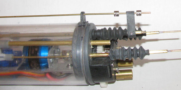
In this photo the control rod has been moved to the vent position.
The o-ring seal has been moved away from the air manifold about 1/4".
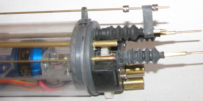
In this photo the control rod has been moved to the air pump on position.
The o-ring seal is in contact with the vent manifold.
(there will be a small spring between the plastic piece and the left
wheel collar that will put a little pressure on the vent valve in the closed
position)
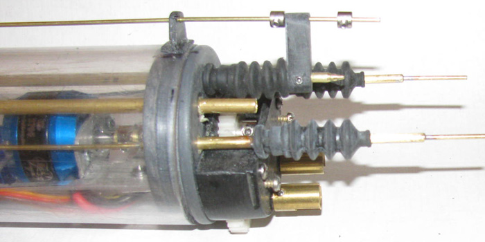
I still have to get the speed controller in there without binding.
April 16th ================================================
Using my short test cylinder, I have been trying to get the speed controller
in to the cylinder.
It actually fits while loose.
Observed where the speed controller centered itself, I am going to
mount it using that position.
Something I noticed is the plug I am using is too big.
It happens to sit where there is not enough room for the plug.
This causes the cylinder not to go over the plug and Rx box.
I looked for smaller plugs and found some that might work.
However it turns out I only have the female side.
Next option it to solder the power wires to the speed controller directly.
This is how I had it originally but got tired of unsoldering and Resoldered
the connections.
When things open up, I will look for the other side of the plug.
With the wires soldered and no plug and shrink wrapped, there is room
for the wires to go under the Rx.
So I have put the couple of drops of silicone glue on the bottom of
the speed controller and put it on the electronics tray. . .again!
A thought.
Once the speed controller glue cures and I have test fit the tray in
to the cylinder, I think I will silicone the power wires to the bottom
of the Rx box so they stay put.
This will put the wires right at the through the ballast tank tube.
This adventure has me thinking I do not want to build any more small
diameter boats.
The Gato is long but is so small in diameter.
2.5" cylinder is not for me.
Of course I have the George Washington to rebuild and its 2/5" cylinder.
But it only needs 2 servos and it uses a very small geared main motor
that uses a very small speed controller.
I think the GW has all it's equipment in a 2" cylinder and I am going
to 2.5".
April 17th ================================================
Early this morning, I did the weekly to town for mail and groceries.
Got it done early because weather said it was going to rain about noon
on.
Noon came and went.
No rain but lots of clouds.
I decided to do a little weed cutting.
I have a back yard that is about 100 by 100.
There is lots of stuff just sitting around that has not made it to
the dump or out back where it should be.
Today is the second attacking the weeds with the weed eater.
I am getting old and all the hospital stuff this past year has taken
my strength but I have to do this.
So when I started this a few days ago, I thought I would do sections
and about 30 minutes at a time.
I swear the weeds are growing a foot a day.
When I stopped for today, I see I have cut maybe 1/3 of the area.
So, a few more days and I will have it.
The ugly part is there is more outside the fenced yard.
Don't know how much because I will only do that that is around my out
building and metal piles.
Say, 300 by 400.
But then I might just cut near my backyard fence and let the rest die
off when the heat gets here in a few weeks.
This may sound like a lot but consider I have 10 acres and I have no
intention of cutting it all.
I tried to keep what I use under 2 acres.
Because there is so much stuff (junk) on the property, I can not use
a tractor.
I tried spraying one year.
Worked great.
BUT, I had to move out for a week.
Not doing that again.
I plan to work on the boat some tomorrow.
April 18th ================================================
A late start but I made it out to the shop.
I removed the clamp and rubber band that were holding the speed controller
in place while the silicone glue cured.
2 days should do it.
I moved all the wires around so I could slide the electronics tray in
to the cylinder.
Lined it up and it all slid right in all the way to the end cap.
Nothing is binding.
Everything is clear of the cylinder wall.
Time to work on routing the wires so it looks good and keeps the wires
in place .
I have room on both sides of the speed controller to run wires.
Now it is just matter of seeing which side is best for the wires.
Maybe I will use both sides.
There is a lot of excess wire.
Rudder and planes servos are only 1½ away from the Rx plugs.
The ballast tank vent servo is right above the Rx so maybe ½.
That leaves a lot of wire to bundle and keep in place.
I have two options I can use.
Tie wraps or like in the past, I use large shrink wrap tubes but do
not shrink it.
I stuff the wires thorough the tube and if I have to I can stretch
it a little and let it rebound back capturing the wires.
A note: I tested all the servos, speed controller and pitch controller
on the rear electronics tray. (all good)
I do have to look at the propeller gear box.
It is binding a little.
I may have gotten 1 or more of the 3 gears too tight to the mount.
It might just need a little grease.
It should not be a big deal.
It was working last week just fine.
April 19th ================================================
Installing the electronics in to the cylinder.
I got all the electronics in to the cylinder.
It all more or less dropped in as I went.
Time to power everything up and test it again.
Rudder.
Stern planes.
Pitch controller.
Air pumps both stages.
Bow plane retracts.
Bow planes pitch.
Lost signal rise on the bow planes.
Main motor.
Main motor not good.
It will run but it will not run at slow speed.
The motor bogs down and stops.
Pulled the electronics tray out of the cylinder.
Motor runs good even at very slow speeds.
Okay, now to look for the cause of the binding.
If I stress the aluminum tray, the motor will bind.
So, the tray must be bending in the cylinder.
I used a straight edge ruler (6 long) and checked the aluminum tray.
The tray is straight to the ruler.
Slide the tray back in to the cylinder.
Rotate the cylinder to see the edge of the aluminum tray.
Put the ruler against the cylinder and check.
Over the length of 7 the tray has a 1/16 bow.
Pulled the end cap out enough to expose the o-ring but still have the
end cap in the cylinder.
The end cap dropped not quite 1/16 off the o-ring.
The motor runs good again.
I need a 1/16 drop in the tray between the servos and the air pumps.
Not enough room to do that to the tray by bending the tray.
Disconnect all wires.
Out to the tool shed.
Cut the tray on the bans saw close to the servo mounting screws.
Using a file I made all edges smooth. (hate sharp edges)
Slide the rear part of the tray in to the cylinder.
The part of the tray mounted on the end cap with the motor.
The tray is now straight.
Now to figure out how to connect the two halves of the tray back together
with no binding.
The part of the tray removed is where the motor speed controller was
mounted.
When I rebuild the tray section, I think I can raise that section up
about 3/32 giving more room for the speed controller so it does not touch
the cylinder at the bottom.
Another plus is I think I can make this section out of plastic which
is a lot easier to shape.
April 20th ================================================
Had lots to do in town.
Getting a late start in the shop.
Yesterday's Exacto knife incident looked worse than it has become.
It may have been 1/4" deep and on the surface there is a 1/4" slice
but it only hurts when I touch it.
I know, "Don't Touch it!"
I have made 2 more pieces for the plastic frame that will attach tot
eh aluminum tray.
Currently in the table vise.
Thought I would see what I culled do about the 2 flags decals that fell
apart .
I have a plan.
I thought I would scan the decals at 1200 dpi.
Clean my printer because it stopped printing red some time ago.
Got the printer working and I did a little editing of the decal flags.
I moved one side towards the center removing the center gap
The gap was there to wrap around the staff.
I am going to print the flags and fold them at the center line.
Careful cut them out before folding.
I will apply water proof glue to the back side of each flag and fold
them over.
Line them up.
After the glue cures, I will use a water proof clear tape and tape
over one side.
Then wrap the tape around the flag staff and on to the other side of
the flag.
The tape will be bigger than the flags so I can trim the tape leaving
about 1/16" to 1/8" of tape out past the edge of the paper flag.
I will paint this with clear paint after I shape the flags so they
are not pancake flat.
The paper flags should be completely enclosed by the tape and the tape
will go completely around the staff.
I think it will do nicely, "IF" the ink does not run when glued.
Care will be taken.
(Going to do a test on a scrap flag)
-------------------------------
I was going to put numbers on the conning tower but the decal sheet
only has enough numbers to do one side.
But thinking that I am not modeling any particular boat, I could put
one set of numbers on one side and a different set on the other.
This would not bother me at all.
I just want something to break up the very plain looking profile.
I thought about weathering but I can not paint a straight line with
tape.
This is going to have to be tomorrow's projects.
I am so sore from weed cutting yesterday afternoon.
I did not get my day in between recovery.
Two days in a row is not good.
April 21st ================================================
Working on the plastic tray for the speed controller.
This is on the underside of the electronics tray.
Side view showing the 3/16" recess of the tray.
Speed controller set in place.
This should solve my problem of the speed controller hitting the cylinder
wall.
Once this cement bond cures, I will drill the two arms to the right
to connect to the aluminum tray.
The arms go beside the 2 servos.
I printed out the two flags for the bow and stern staffs.
I used 2 different glues to seal the paper flags.
1 failed by causing the colors to run and blot out the white areas.
Turned out Thin CA used on the back of the paper and then folded over
and lined up work the best.
There is a little dulling of the white but I can live with it.
After the CA dried for about 40 minutes, I used clear packing tape
to cover one side with enough extending out to cover the other side after
wrapping it around the staff.
Pressed it to make sure the tape bonded to itself all the way around
the flag and on the staff.
I trimmed the tape down leaving a little out past the paper.
In the shop I can not see the tape very well.
In the photo I can see how ragged it is.
Flag size reference. Not quite 1/2" tall.
Bow flag.
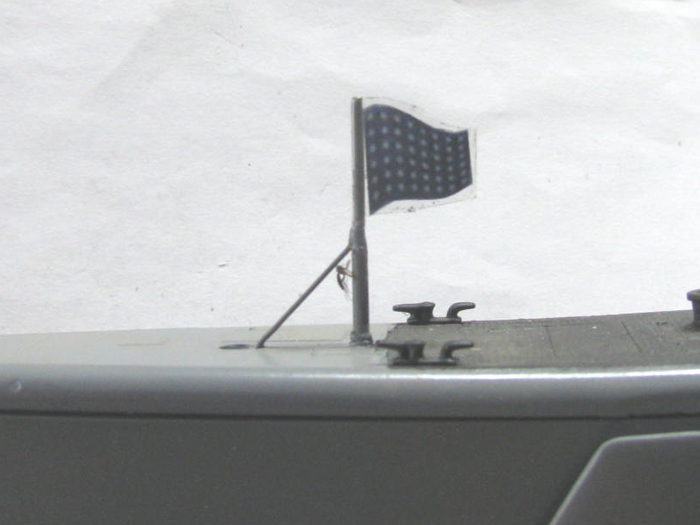
Stern flag.
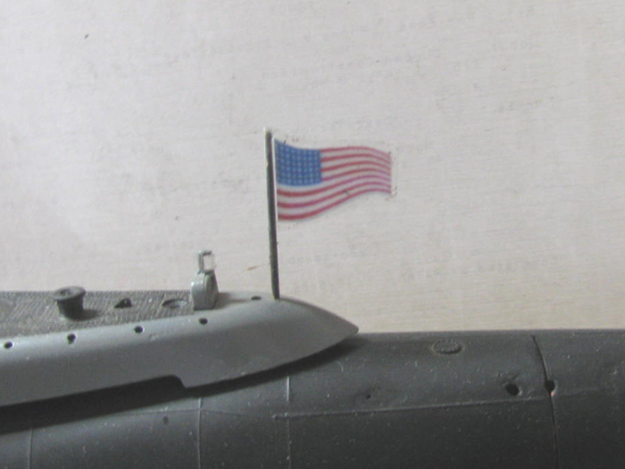
April 22nd ================================================
I had about 20 minutes in the shop.
I was distracted.
I had to remove a power steering pump from my Toyota truck.
Did this after making the aluminum bracket to hold the speed controller
to the underside of the electronics tray.
The aluminum is very thin.
I cut it with scissors.
Filed and sanded the edges smooth.
Did some measuring and bent the aluminum strip.
Drilled 2 holes in the plastic tray and 2 holes in the aluminum strip.
Found a couple of very small bolts.
Cut them shorter because they were 3/4" long and I needed 1/4".
Used the bolts to tap the plastic threads.
Below is what I ended up with.
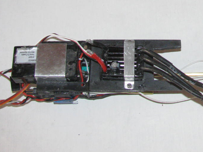
I placed the rest of the tray in to position.
All of this is 8.5" long from the end cap cylinder edge stop to the
end of the Rx.
I ended up with 9" of length to put all this in.
Now I have to rewire the main power and plug servos in.
But this will happen tomorrow or Friday.
I still have to go get a steering pump and reinstall it before I forget
where the bolts go.
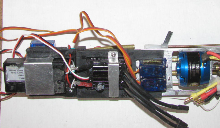
April 23rd ================================================
I test fit the tray in to the cylinder.
I can see the tray sits at a slight angle.
First thought was the capacitor was touching the cylinder wall.
That is not it.
Shining flash light down cylinder I can see the new speed controller
bracket is touching.
Easy enough to change.
Make a new bracket.
This time, instead of making square corners, I bolted one end to the
tray and I shaped the strap by bending it around the speed controller.
No square corners now.
Test fit the tray in the cylinder.
The tray now sits level in the cylinder.
Next, I have to figure out how to connect the two trays.
The motor tray is center of the cylinder and the air pump tray sits
lower.
I could make spacers until I get the correct gap.
I slit the tray because the ar pump side was bending the motor section
and binding the motor.
This is my thought.
If I can connect the 2 trays but have them move independently, they
will find their own center.
Going to try making the connection using 4 pins. 2 on each side of the
2 servos.
The pins will allow the trays to float on the pins.
The reason I even need the connection is so both trays will slide in
and out of the cylinder together for installation and removable for maintenance.
I think I will install 4 brass pins in the plastic tray and drill small
but oversized holes in the aluminum tray.
I had to repair one of the bolt threaded holes so the tray is currently
in the table vise curing.
--------------------------
Moved all the parts from the truck in to the tool shed.
Going to be at least a week before the new parts show up.
Done.
--------------------------
It is going to start getting hot here.
In the 90s in a day or so.
Time to prepare the swamp cooler for the summer.
I do the same when I turn it off for the winter so it is mostly cleaning
out the dust and dirt and making sure the water pump runs.
This takes about 30 to 40 minutes.
Done.
------------------
On to the ugly stuff.
Running the weed eater.
I have done about 50 square this morning.
Going to see if I can do another 50.
And then go back over some of what has been done the past week and
get the up shoots.
If all goes well, I should be done for today by 1 pm.
My arms and shoulders are telling me to be careful.
That I will.
Looks like I have completed 3/4 of the fenced yard.
Not thinking about outside the fence. ;^(
April 25th ================================================
Update.
On Thursday, I over did the weed cutting.
Nothing got done yesterday.
Today, I did a little on the two trays to make them fit together and
not bind the motor.
A lot of test fitting to get the two trays to meet level.
I need some very small bolts which I have bolts but need nuts.
Trip to hardware on Monday.
So I think not much will get done tomorrow and I will work at recovering
from the weed cutting machine.
Sorry to say, I am not done with that either.
The heat has arrived.
So all work needs to be done early in the morning.
April 28th ================================================
After a couple of days off, I got in to the shop.
I did get the needed small bolts, yesterday.
I did the drilling and aligning to attach the motor tray and Rx tray
together.
I did several in to cylinder tests.
Got the 2 trays to where they drop in to the cylinder and the main
motor does not bind.
Got the Tx out and turned on the system to get the servo control horns
back in to their correct positions.
Put the antenna bracket on the rear end cap.
Restrung the antenna wire.
Next, I will work at running all the servo wires and power wires so
they are not just loose and a mess.
Progress is being made.
Maybe slow but just where am I going to go right now.
I still have more weeds to cut.
I am still waiting for the Toyota power steering unit to arrive. (they
say Friday)
April 29th ================================================
The servo wires and power wires are in place.
The power wires are still not finished.
I do not have a small plug to use and the ones I do have are too big
to fit in the space available.
I will be at the auto parts store on Friday to pick up the new power
steering box.
I will look there for small electrical plugs
I may be back to soldering them direct again.
I really would like to be able to unplug the system in stead of unsoldering
the wires.
Again a little progress on the boat.
April 30th ================================================
I end up having to go to town this morning.
While there, I stopped by the auto parts store to check on my power
steering pump for my truck.
It was there and now sits out in the tool shed awaiting me to start
the install.
Yea, tomorrow morning when it's a bit cooler and the wind is not blowing
25 mph.
I looked over the electrical plug parts.
They has something that looked like it would do.
Much like the photo Scott posted above.
Got the package to the counter and was told $8.49.
Yea for 5 pair.
I need 2.
Yea I did not buy them. (I am thrifty = cheap)
On the way home, I had an idea that I could make out of scrapes at the
end of the bench.
I will give my idea a shot and let you know how it came out.
I think I can use brass tubing, 2 sizes and wire cutters to do a little
dimple on the larger tube.
Then shrink wrap it all and tape it to the bottom of the Rx.
This will make the connection no bigger than the wire insulation in
size.
So if the wire can pass then this idea should as well.
I think it will turn in to a big project.
Might take me 5 minutes of so to complete.
Maybe 7 minutes for both wires. ;^)
---------------------------------
Here is my 7 minute project.
Sorry, it took 8 minutes.
Brass tubing from the scrap box.
The largest pieces are 1/8".
The others are the next size down that slips in to the 1/8".
Cut the needed pieces to length.
Test fit and then soldered to make plugs.
After soldering and filing the parts clean of excess solder, I slipped
them together for another test fit.
Parts slipped all the way together.
The wires will fit in to the ends of the 1/8" tubing to be soldered.
(the wires are for show and tell only)
The shrink tubing will cover the exposed brass when connected.
There will be a cut at the joining of the two ends.
I did the testing to find out how much I can put a dimple in the outside
tube that will bind the inside tube but still let me pull the plugs apart
for service.
1 dimple abut center of the inside tube on the outside tube will do.
This will bind the inside tubing with the most contact between the
tubes.
Also during the test, I punched the outside tube a little too much and
could not get the inside tube all the way in.
Took a under sized drill bit and ran it through the bigger tube.
A couple of passes fixed the over punch.
So I will need to be careful when I punch the final tubes.
But if it goes wrong, that to can be fixed.
May 1st ================================================
I worked on the power wire connectors.
My thought was to make the pieces slip together and held in place with
a little dimple.
But then I though if I split the larger tube and then squeezed the
edges in a little, I would have a compression fit full length of the smaller
tube.
I put the large receiving tube in the table vise.
Using my razor saw, I cut about 1/3 of the way through the 1/8" brass
tube after measuring how long the small tube would go inside the large
tube.
After making the cut across the tube, I used the thinnest Dremel cutting
wheel I have and cut from the end of the tube to the cross cut..
Not all the way.
I used the Exacto knife to cut the remain little bit..
I did not want any over cut.
Filed the inside of the 1/8" tube and then filed the outside to make
it smooth.
Using pliers, I put a little crimp in the cut edges to bend them inward.
Did a little adjusting on the bend until I could push the small tube
into the larger tube.
The fit is very tight.
I have to use pliers on both pieces to pull them a part.
Here are the connectors with the receiving end split.
I had a photo of the pieces together but the photo when enlarged was
too blurry to use.
Next is to solder the wires in to the ends of the connectors.
Another issue has come up.
I do not have the correct size shrink tube to over these parts.
I have smaller and bigger (way bigger)
May 2nd ================================================
The brass tube connectors have been soldered to the wires.
The plugs are about half way in.
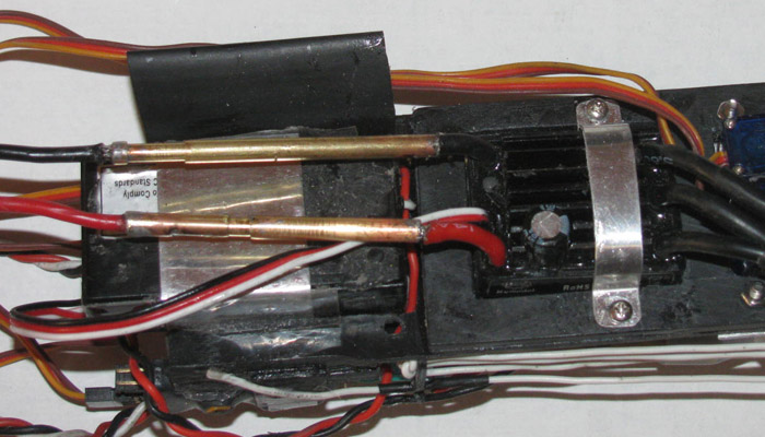
I went to town and got shrink tubing. (the correct size)
Here the tubing has been installed and trimmed at the joint ends.
Again about half way in.
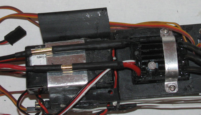
Here the plugs have been pushed all the way in.
The wires will now sit under the Rx and in the curve of the cylinder
without touching.
I will silicone a larger shrink tube ring on to the Rx bracket to hold
the wires in place closer to the center line.
No more soldering and unsoldering wires to do maintenance.
Plugs!
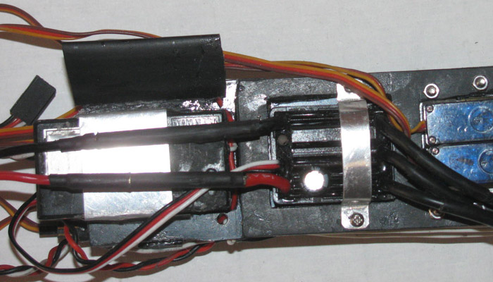
The black piece above the Rx is large shrink tube that I can push the
excess servo wires through to clean up the look and keep the wires from
moving around.
May 3nd ================================================
Today, I planned to install the power steering unit in my little truck.
Got out there at 9:00 am.
The wind had already started up.
Dirt and dust was blowing about.
Not a good time to be installing a hydraulic pump.
So I did not start on it.
Went in to the shop to work on the Gato.
Opened the door and what did I see, dust swirling about.
So much dust that the deck board slots where almost covered over.
Not a good time to be messing with small parts.
So, today was a total "can not" get anything done day.
Maybe tomorrow.
May 4th ================================================
No wind this morning. (yet)
Installed steering pump and hooked everything up.
Truck is now ready for test drive.
I just happen to need to go to town for propane.
That's what I was going to do when the truck steering gave up.
I am on back up propane at the moment.
I might even get in to the shop this afternoon if the wind stays down.
May 5th ================================================
Well the test drive yesterday went well.
This morning however brought to light that there is another issue.
The steering pump fluid tank was empty.
This means I am going to have to look father in to the steering problem.
I put fluid in the pump tank and move the truck back to the tool shed
and put the front up on stands.
I got a 3 gallon bucket and boiled some water.
Added laundry soap and poured the water in.
Out to the truck.
I have a pressure washer wand that I can plug in to my air hose.
It has a long clean rubber hose I can put in the bucket for it to suck
water and soap.
Started by getting on the ground and spraying all the steering parts
and other under engine parts.
Even did the front axle parts.
Got out from under the truck and sprayed down from above.
Finished with the soapy water and then use clear fresh water.
I will let it sit until tomorrow of the next day to dry.
Next I will fill the pump tank and get under the truck with my flashlight
and look for oil leaks.
There are two hoses from pump to steering box.
So, there are 4 fittings that can leak and the box itself with its
many seals.
I have checked on availability of a rebuilt box.
There are two in town.
Watch a video on removing the box.
Not much different than all the fords and chevys I have done over the
years.
2 splines and 3 bolts.
Only thing is, I do not have a pitman arm puller. (yet)'
Should not be to difficult to make one.
---------------------
\Boat progress.
I did before I worked on the truck, make and mount a shrink tube part
to hold servo wires.
I located where to put it and glued it in place. (silicone for easy
removal later)
The tube is currently rubber banded to hold in place while it cures.
Return to water trails may happen this week.
May 6th ================================================
Last start today.
Got outside and it was too warm to crawl under the truck to look for
the fluid leak.
So, in to the shop I went.
Got the rear electronics tray in tot he cylinder.
I did prep it will grease on the o-ring as if this was a final assembly.
Moved on to teh front electronics tray.
As I hooked up the 2 battery leads, the 2 servos and Fail Safe.
There is also a plug to the power switch.
That is a lot of plugs.
And there are two big yellow plugs.
As I was bunching up the wires to put them in the cylinder, it became
appearant to me that I could remove 1 of those big yellow plugs.
There was no reason to have 2 plugs to do the job that 1 could.
So I plugged in the soldering iron.
While waiting for it to heat up, I cut the shrink tube of the previus
connections and the switch.
Un soldered the switch plug and the main power plug.
This removed 4" of 2 wires and 1 male and 1 female yellow plug.
Connected all plugs.
Turned on the txx and then the Rx.
Slowly checked the control operations.
Everything works and works in the correct direction.
The Fail Safe works at 6 seconds.
The Pitch Controller works in the correct direction.
I have greased up the o-ring and everything is now ready to close up.
---------------------------------
As I was stuffing all the wires and batteries in to the front of the
cylinder, it became very apparent that once the boat was trimmed, I may
not be able to get all this stuff back in the cylinder in the same order.
This would upset the trim and I would have to move ballast weights
each time.
Going to fit this.
I started by making an aluminum tray for the batteries.
It is mounted to the servo tray.
I will get a photo when the tray comes out of clamps and vice.
This will keep them in the same place all the time.
Even when the tray is removed for charging.
I have to move the power plug, again.
But I think I can mount it permanently under the batteries on the tray.
Then I only have to deal with the servo wires and main power wires.
May 7th ================================================
I have not had time today to work in the shop.
Truck and other things have to be done.
But as promised, I did get in the shop for some tools so I took photos
of the new battery tray.
New battery tray installed on front electronics tray. (bow planes retract
and pitch servos)
The batteries I am using are 850 mah each.
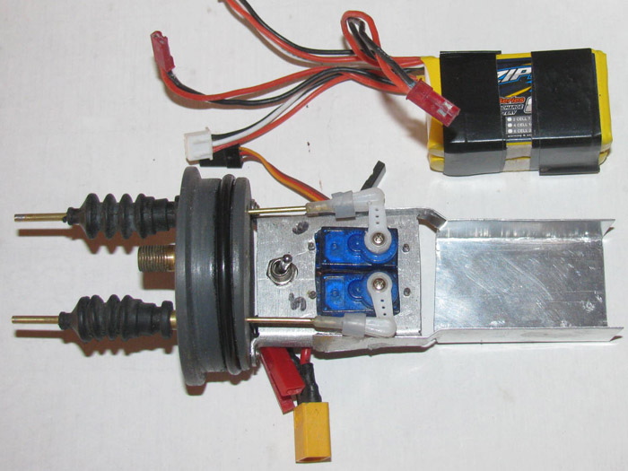
Batteries set in to tray.
All wiring is under the tray
That big yellow plug is going to be replaces with something smaller.
It has been the problem all along.
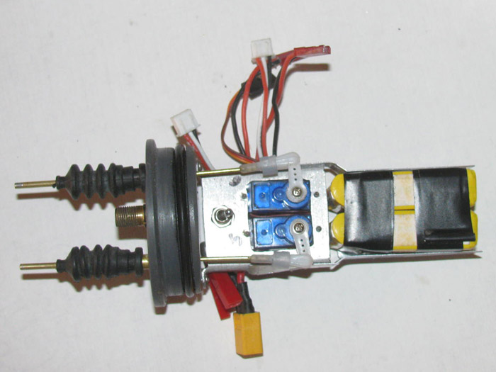
Side view showing there is room under the tray to run 2 servo wires
and the power wires.
I looks like I can shorten the battery tray.
The battery tray is siliconed to the servo tray at this time.
It is very strong but I think next trip to hardware store I will get
4 very small bolts to secure it all together.
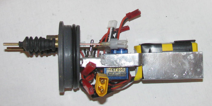
May 8th ================================================
I have trimmed the battery tray to length.
Decide to make a back strap for the battery tray.
I bent aluminum piece to fit the back of the tray.
With the battery in place, I held the back strap in place and then
pulled the battery out.
This caused the back strap to move about 1/8" out to allow the battery
to tip slightly and come up and out.
Filed all the sharp edges round.
Applied a bit of silicone glue to the outside edges of the tray where
the strap will be.
Got 2 small clamps ready to hold on the strap.
Put the the batteries in place.
Put the strap in over the silicone glue.
Carefully removed the batteries moving the strap to the propper location.
Clamped the strap in place making sure that the strap did not move.
Before putting the clamps on, I placed black tape on the tray at the
edges of the strap so I would know exactly where the strap should end up.
Work as planned.
Later today, I hope to do the new plugs for the power wires.
I got to get to town.
I have things to do there.
------------------------------------
Delivery driver just left.
Replacement office chair is here.
I'll assemble when I getback from town.
May 9th ================================================
The new battery tray.
The wires will exit the tray towards the servos.
The end of the tray is open so all the wires will go through.
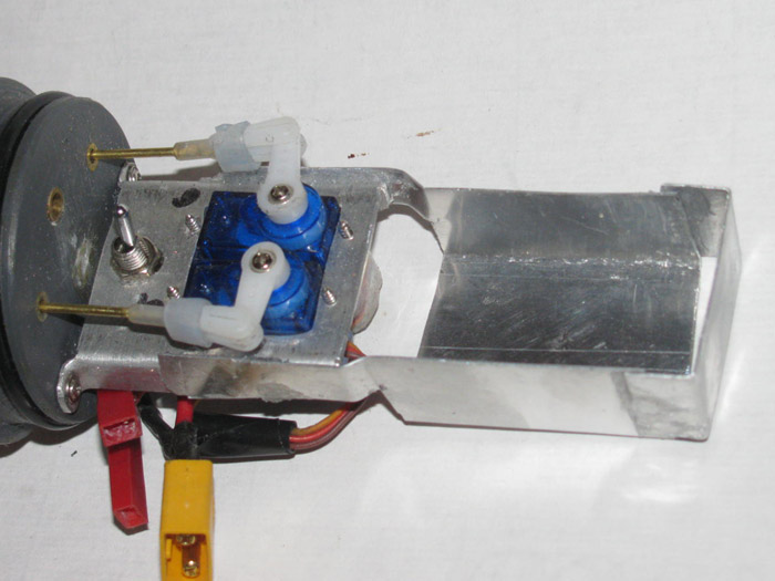
Two 850 mah batteries. (these things are small)
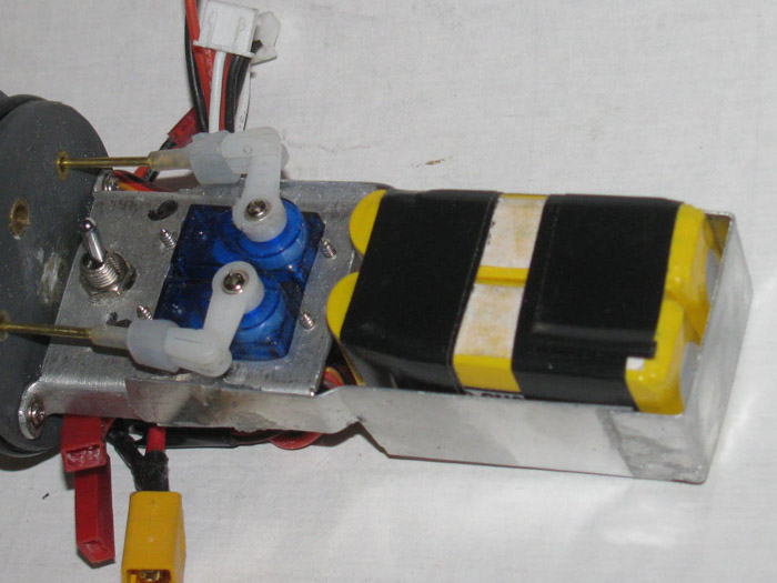
Next is to make new power plugs because the yellow plug is too big.
(one half at bottom of photo)
Here I have made new plugs using brass tubing.
I will place electrical tape on the bottom of the tray so the plug
joints can not short to the tray.
Though the tray is not electrically connected.
New plugs half way together.
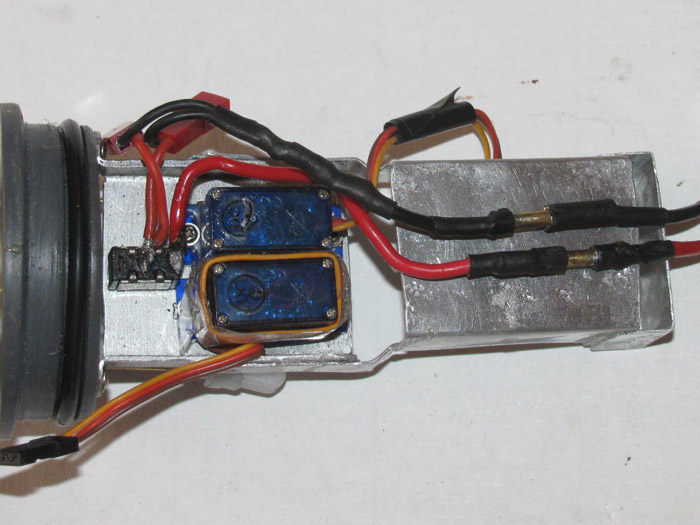
Plugs all the way together,
I see I need to work on the fit on the lower plug.
The solder maybe high there and a little filing will fix it.
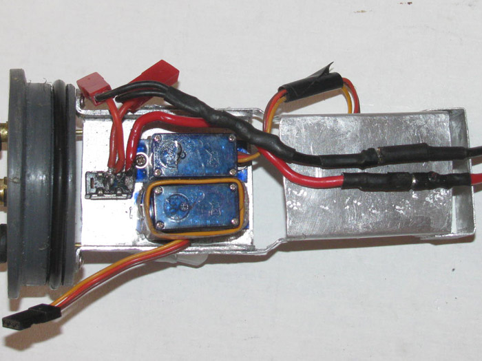
Same photo as above with the yellow plug I removed.
It would not fit between the electrical tray and the cylinder wall.
Now I have a flat surface on the side of the tray to mount the pitch
controller.
Had not planned it that way so it is a pleasant surprise.
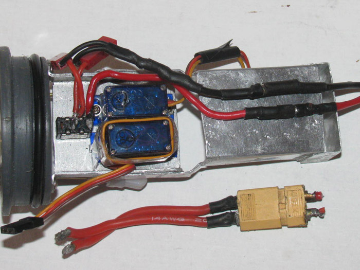
--------------------------------------------
August 14th ================================================
I got up and went out to the shop.
I was going to make plastic parts for the GW ballast system.
After about an hour, I was ready to start assembling some of the plastic
pieces.
Arranged them on the work bench and got the plastic cement out.
I sanded the surfaces to be joined.
I lined them up on the work bench in the order of assembly.
I got 3 parts put together then it happened.
I had gotten so hot in the shop, the brush as sticking to the part
as I tried to put cement on it.
2 attempts and I knew the morning was over.
Put things away for the day.
I went to town for mail and gas.
At the post office, I got a go to window pick up notice.
There I received a small box.
From Shanghai.
Got home and opened the box.
My last order has arrived.
The parts for the Gato are here.
But with the GW all over the bench, the Gato will have to wait a few
days.
June 2, I place order.
July 21 on its way to USA.
August 2 it arrived USA. (customs hold)
August 11 or 12 it was released for delivery to local post office.
August 14 it arrived at my post office for pick up.
All the parts I ordered are now in hand. (servos and Rxs)
I can now get back to work.
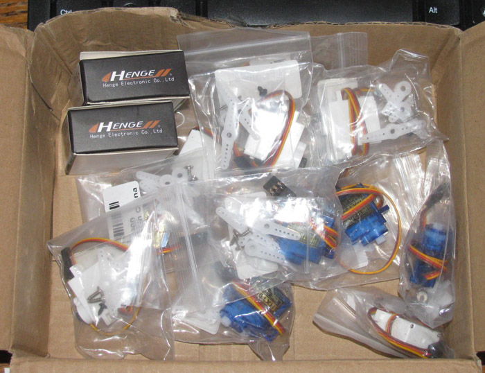
September 13th ================================================
Didn't know what to do today.
Scheduled for eye surgery on Tuesday, I can not grind, cut, sand or
spray paint until after the surgery.
So what to do.
I know.
I will install the new servo on the Gato electronics tray. (the white
servo)
The new servo is the same size as the one that failed.
Only differences I can see from the spec are these.
The new one has metal gears. (the original one kept stripping gears)
The new one has a little more torque.
Installing was a matter of 2 screws holding the servo.
I connected it to the Rx and did the test before connecting the servo
to the control rod.
Needed to center the control horn for the proper throw.
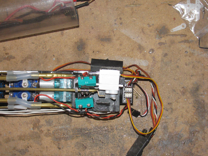
Connected the control rod.
Turned on everything and tested.
Okay there is a problem.
The control rod is hard to move.
I removed the boot seal on the control rod so it would move freely.
That was not the case.
Disconnected the control rod from the servo and hand moved the control
rod.
There is a problem.
It is very hard to move.
Removed the control rod from the end cap bushing.
Cleaned it up with 400 grit sand paper.
I pushed the control rod through the bushing from the back of the end
cap.
A little more cleaning.
Now it moves freely.
But there is another issue.
I pushed the control rod all the way through to the guide at the servo
end.
Well, that is not right.
The end of the rod hits 1/16" off center of the guide hole. (it's and
over sized hole)
Removed the control rod and took my small round file to the guide hole.
I needed to make it larger to the right.
I know this will make an oval hole but I can fix that later with a
brass tube piece as a bushing and make it oversize by 1 size.
Now I have moved the control rod and it moves freely.
Well that did not work out well.
The control rod not hits the edge of the #2 pump switch.
I have to move the control rod back to it's original position.
It is a long control rod so I put a slight bend in the middle of the
rod between the end cap and the guide at the servo end.
This seems to have made the control rod move easily.
Why not?
Next problem.
The control rod end at the servo end is not lined up with the servo
control horn.
I used a 1/16" a brass rod to connect the 2.
But the rod twists and does not move the control rod fully.
I used the Tx to move it back and forth and the rod finally disengaged
and fell loose.
I think I will make a plastic clevis gizmo.
It will replace the 1/16" rod connector.
It will have plastic down both sides of the servo horn so the connector
can not twist.
It will also go down both sides of the control rod connection point.
These parts I can make cut using scissor to cut the pieces.
They are glued and in the vise.
This should resolve all the issues I found.
---------------------------
The plastic connector between the control rod and servo is in place.
I need to trim the 1/16" brass rod once I figure out how to keep it
in place.
Right now there is a lot of friction holding it but as it wears in,
I need something more positive.
Tested it with Tx and cycled it several times.
No twist at all and it is smooth again.
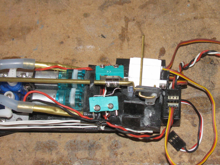
September 22nd ================================================
Made it out to the shop.
I don't think I can do much but there were a couple of things I thought
I would survive.
I reinstalled the pitch controller. Irequired setting it in a line of
silicone glue to hold it in it's cradle.
Set it in place and made sure it was level with the electronics tray.
The cradle is to the right of the bottom green switch.
Started bringing the servo wires back to the Rx.
They go through a tube to hold them from moving around and guide them
past the control rods.
This tube needs a little more silicone to hold it in place as well.
The tube is seen behind and above the white servo.
Looking at the photo, it reminded me I also trimmed the ballast tank
control rod U pin and placed small plastic circles over the ends and glued
in place to hold the pin to the control rod and servo.
I did the gluing knowing it would have to sit over nigth before doing
more.
This forced me to not do too much that might harm my eye as it heals.
September 26th ================================================
George Washington before modifications.
Modificaions are;
the hull was a "Z" cut hull, now it is a center line cut.
All of the electronics was removed and disassembled.
A new 2.5" cylinder is going in place of the 3 cylinder system.
Ballast system has been completely changed.
Currently rebuilding electronics tray.
After the hull was rebuilt as a centerline cut hull, it got new paint.
I still need to finish the rudder paint lines.
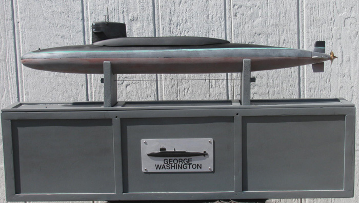
I was in the shop to continue the cylinder reassembly.
I found a wiring issue and I am correcting it.
A little solder here, a little solder there.
Got it together and powered it up.
What, no power to the servos.
Okay, time to unplug every thing and start over, 1 at a time.
WHile it is open, I charged the batteries which really didn't need it.
But the are fully charged now.
-------------------------
I got out my trusty multi meter.
I checked every wire in the system for continuity.
There is a lot of wires. . . .
Okay, this worked out well and I did not find any open wires.
Next I need to check for shorts across wires.
Power wires are okay.
The rudder and stern plane servo wires are okay.
The air pump/ballast vent servo wires are okay.
The bow planes wires are, . . not okay.
There is a short between the power and center wire.
The third wire is okay.
The bow planes retract servo wires are okay.
So I pulled the bow planes servo wires out of the cylinder.
There are 3 the wires from the servo to the extension wires that go
through the ballast tank tube.
Servo wires okay.
Now that I have eliminated every thing but the extension wires, I will
check them to find the short between the power and center wire.
This did not take long.
As I was turning the plug that goes in to the Rx, I notices the insulation
was soft and slightly melted.
Closer examination shows the power side and center are melting together.
Using the multi meter, I checked across the pi9ns in the plug.
Sure enough there is a short.
But exactly where is the short?
The plug has to go. (trash)
I got another plug with about 6 of 3 wires on it.
Cut every thing to length and stripped the insulation of all 6 wires.
Now is the time to check the rest of the original long wire from the
bow to the Rx in the stern.
This long wire is good.
Check the cut off wire I tossed in the trash.
There is the short.
So the short is now in the trash with the end plug.
Installed new plug end.
I pulled the wires through the ballast tank tube.
I have had enough of this small stuff for today.
Calling it quits.
September 27th ================================================
Morning progress.
Tested the wires again.
No problems found.
Test each item as I plugged it in to the Rx.
Had 2 issues.
1. The throttle was not on the correct channel.
Instead of ch 3 it was on ch 6.
Okay, I know what I did.
I counted from the wrong side of the Rx.
2. The bow retract servo was not working.
There are a lot of wires everywhere.
Found that the long extension servo wire on the servo end was reversed.
Everything now works correctly.
Pulled the end caps off just a little.
Enough to get to the o-rings.
Removed the o-rings and cleaned.
Applied silicone grease and reinstalled.
Installed the 2 safety cables that keep the end caps from popping off.
Though this ballast system should not put pressure in the cylinder.
The bench has parts on it for 2 submarines and 1 large old scow schooner.
Looked and found the Gato vent control rods and springs.
Installed vent system control rods.
Checked everything again.
All is correct.
Next step is putting the cylinder in the hull.
Filling the trim test tank with water.
Do the water trimming again.
Of course I am not sure when I can do that.
Life is getting in the way . . . again.
An update is necessary at this point.
I was reading another forum where I found a photo of my bow planes and
retract equipment.
Reading the poster's comments and another poster's comments on how
not to put a the Fail Safe on the bow planes.
Reason given was rotating the bow planes in the up stored position.
I did a lot of test on my bow plane equipment.
I chose to put the Fail Safe on the bow planes.
The testing showed that the bow planes work in the deployed position.
The also work in the up and stored position.
They rotate correctly but will have no effect on the boat because the
bow planes will just move back and forth with no engagement in the water.
My reasoning for using the bow planes is the boat ballast system is
a air breather and must be on the surface to draw air to bring the boat
up to waterline.
If the boat is submerged the air pumps will pump water which will have
no effect on the boat and it will not come up.
Now as far as the bow planes operating stored on the Fail Safe is not
very likely.
Stored the boat is on the surface and the Fail Safe will probably never
be activated.
Before submerging the bow planes will be deplyed in the out position
and if the Fail Safe activates the bow planes will be in the waster pushing
the bow up to get the signal back and where the air pumps will get air
to the ballast tank.
This got me thinking.
So out to the shop I went.
First checkall controls to make sure they work.
Lifted the rear electronics tra to see if the Auto Leveling works on
the rear planes.
All good.
Looked at the front electronics tray.
No I wonder if I have 2 Auto Levelers in the system. ? ?
It looks likes the same as the AUto Leveler in tha back.
Lifted the front electraonis tray.
Nothing happened.
Nothing should have happened.
Now I turned of the Tx.
Several things happened I was not expecting.
First thing was the air pumps came on.
This is not suppose to happen.
Turn the Tx on and off a few times.
The air pumps finally did not come on.
While doing this, I noticed the bow retract rotating.
This is not suppose to happen.
Looked over the servo wires.
Can not see every thing.
Pulled the front electronics tray out of the cylinder half way.
Well I can see what is happening now.
I have the bow retract servo plugged in to the Fail Safe.
I am sure this happened because plugging in equipment was done with
the elctronics tray bottom up.
This of course reverses the servo location.
I plugged the wrong servo in to the Fail Safe.
Tomorrow when my eyes are fresh, I will look this over again and do
the necessary wiring fix.
I think it's a matter of unplugging the servo from the Fail Safe and
plugging in the other servo.
Not just reverse the plugs but remoe 1 from the FS and plug the other
one in to it.
Thank goodness, there are only 2 servos on the front electronics tray.
----------------
I think I will also check the Tx programming to see if the channel
the air pumps are on is set to a fail safe position.
I do not want the pumps coming on during a signal failure.
==================
The Gato and my George Washington have made me realize I do not want
to build any more submarines with small diameter cylinders.
3" minimum.
Maybe 3.5" minumum.
September 29th ================================================
I was in the shop working on the bow plane servos.
I had the Fail Safe on the wrong servo. (bow planes retract)
Unplugged the 2 servos.
1 from the Fail Safe.
Reversed the plugs and tested.
Okay.
Siliconed the plugs so they do not pull apart while pushing the electronics
tray in to the cylinder.
I am going to let it cure.
I need to get back to real life to finish what I need to.
--------------------
I do have an issue that so far I can not figure out.
On lost signal by turning off the Tx, I have 2 servos cycling.
1 is the ballast tank air pumps go to full on instead of staying centered.
2 is the rear planes move up and down a few times before stopping.
Not sure this will be a problem but I would like to know if I can stop
this from happening.
The bow plane servos do not move at all until the 7 second mark of
lost signal.
Then the bow planes rotate to full up which is what I want them to
do.
It's all those other servos moving before the 7 second mark.
I need to test again and watch the rear servos to see if they stop
centered after the 7 second mark.
The stern planes moving can be an problem if they cause the boat to
dive deeper during lost signal.
The air pumps running is not a big problem as long as the water does
not damage the pumps.
If they are running when the mast break the surface, the pumps will
get air in to the ballast tanks.
One good thing is, I do not see the ballast tank vent cycling so the
tank will not loose air when getting air.
I know this because the servo that runs the air pumps also open the
vent.
If the pumps are running the vent has to be closed.
September 30th ================================================
It seems I have this morning to work in the shop.
Going to see what I can get done on the Gato.
Finish closing up the cylinder.
I think I need to make a 90 degree air fitting.
I might have some plastic air hose fittings that could do the job.
I need the air hose to turn under the deck coming out of the conning
tower.
Put the cylinder in the hull and cut the control rods to length so there
is minimum extra brass rod over lap.
(right now I think there is over 1.5" over lap)
I think I will see if I can make the two antenna lines from the conning
tower to the front flag staff.
I think I might paint the bottom of the hull fouling.
I have come to like the GW bottom paint.
But a bit lighter than the GW.
Time to get out there and do stuff.
--------------------------------
I had the cylionder almost completely assembled.
Then I noticed I did not put the plastic keepers on the brass "U" pin
that holds the ballast control rod to the servo.
Disassmble the electronis.
I have to slide the front tray out to straighten the wires that go
through the ballast tank.
Once the wires are straight, I can pull the rear electronics tray out
while feeding the wires through the brass tube.
Got that done and put the "U" pin keeper on.
I CA this in place so I lfet the tray out while curing so as not to
fog up the cylinder tube.
Found the plastic hose fittings.
They are all tee with different size barbs.
Look through them until I found 1 with 2 1/8" barbs are 90 degrees.
Cut theother barb off. (it was 3/16")
Made a plug to fill the hole where the barb was removed.
Glued the plug in.
After it cured, I held it to the deck and measured for the air hose.
When installed in the conning tower, the fitting will be above the
cylinder by about 1/8"+.
No more fighting the curve in the hose so it did not get pinched.
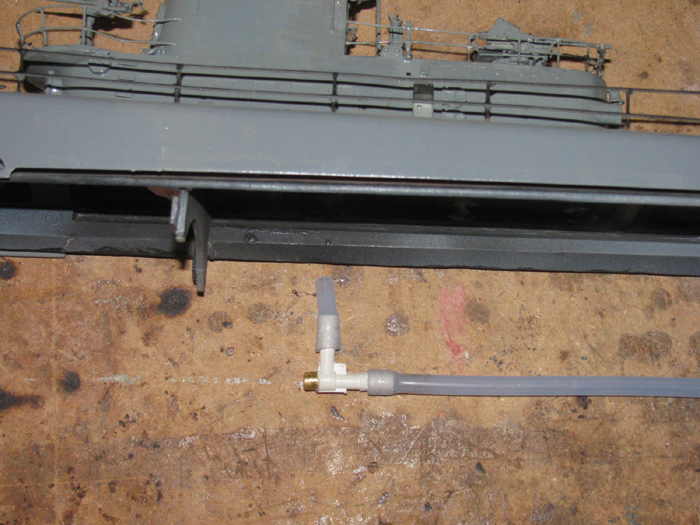
Still letting the CA cure before assembling the cylinder, again.
Looking at the lower hull to put a waterline on with tape for painting.
Sanded with 400 wet/dry to scuff the paint a little.
Well, I found something I did not do back when building the lower hull.
I did not fill the bow to center hull joint line.
I get a small plastic scrap and sand it flat.
Used it to spread the glaze on the seam.
There will be sanding tomorrow.
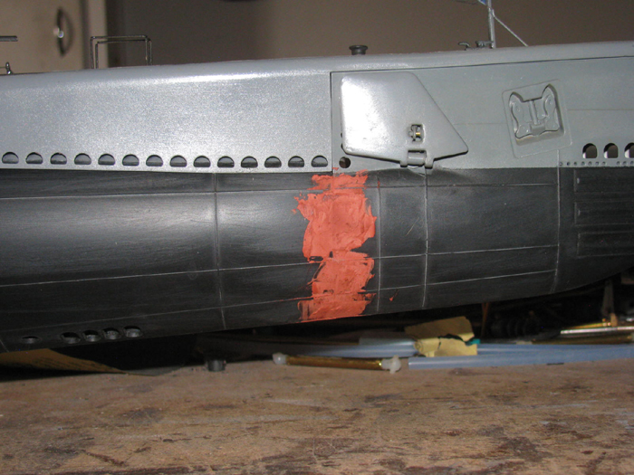
Looked at a few old photo to see how the radio antenna was strung on
the bow of a rear main gun boat.
Only thing I saw that I did not know was there is a cross bar on top
of the flag staff to spread the wires.
Not a roblem.
Looked for black heavy thread to use as the antenna wires.
I have some that is too big and I have some that is not strong enough.
On my list of things to get next time in town.
Control rods not sized or cut.
Time to stop.
My new neigbor to the north has a big John Deer crawler and is grading
and leveling 10 acers.
They started about an hour ago.
Theyhave been at it for 2 weeks now.
Too mush dirt dust to paint or do any more gluing.
October 1st ===============================================
The bow to hull joint has been sanded.
Flat black hull paint is done. (I painted the entire lower hull, flat
black)
Might as well clean it all up.
Now I have to decide if I want to put a little lower hull water fouling
on.
I think that is going to happen because I have already setup the stand
to hold the hull level, bow to stern for running a pencil waterline for
taping.
Going to let the black cure over night so it is easier to handle during
the line drawing.
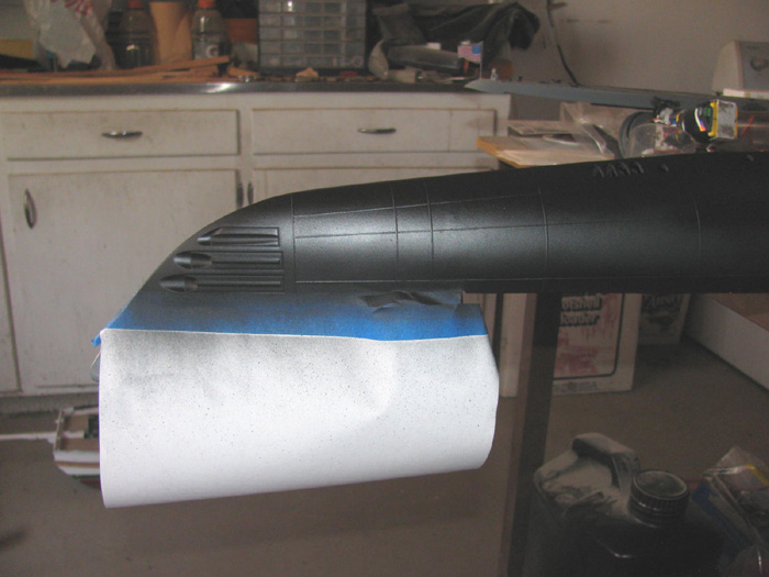
October 2nd ===============================================
Today, I started by penciling the waterline on the hull.
Made sure the hull was level bow to stern.
Made the wooden block to set the pencil on to trace the waterline.
Did the first side.
Turned the hull around and measured the height just to double check.
Traced the second side waterline.
What's this?
I found the stern joint on one side needed a little attension.
I had filled the gap but did not sand down the joint miss alignment.
There is a very small step from the center hull to the stern section.
Not a problem.
Took a small file to the gap edge.
Sanded the paint so the glaze will hold to it.
Filled the gap which is not much and leveled out the small step. (1/32"
maybe but noticable)
The glaze is now curing.
I checked the pencil waterline marks on both sides.
Looks good so far.
After sanding the glazed joint, I will lay down the flat black in that
area.
Probably later today I will be able to do that.
My plan is to be able to tape the waterline in the morning and then
start the white and light grey fouling paint.
I did some practicing this morning.
It looks like I can get the light misting of paint from about 4' to
4.5'.
This will need to be done when there is no wind at all. (this morning
was good but I did not have everything ready)
---------------------------
Finished the sanding of the rear hull joint.
Does not appear to need a second coat of glaze.
I do need to put the weld lines back on the hull.
This is not hard to do at all.
It does take a bit of time because the weld lines have intersections
that I do not want to cut in on the tape so, I will do lines one at a time.
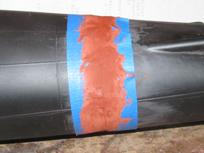
October 3rd ===============================================
Sanded the vertical weld line.
Taped the horizontal lines.
Applied glaze.
Will sand a little later today.
My plan for today is to finish the weld lines, repaint the flat black
and start on the fouling look.
If the fouling on the GW holds, the fouling takes about 10 minutes to
apply the paint.
It is all just over spray and then rubbed down with a tee shirt rag.
The more un even the paint is, the better it looks when rubbed down.
There may be some very light sanding with 400 wet/dry to get the vertical
band look.
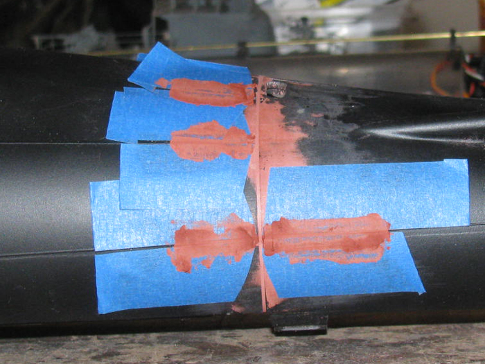
Sanding the weldlines in is complete.
I will run some 400 wet/dry sand paper over the weld lines to knock
the sharp edges off.
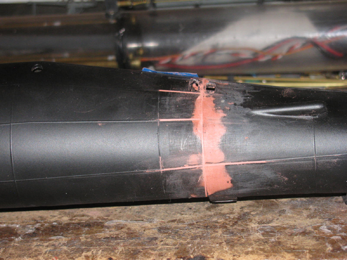
I have begun taping above the waterline penciled on yesterday.
The tape actually stops two weld line before the repair on the stern.
(reason the tape curls up at the stern)
I still have to paint the flat black in that area.
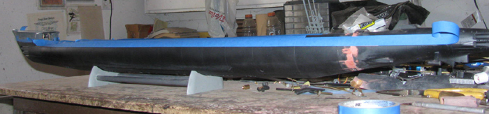
The glazed area is now painted. (I will get a photo before I do anything
else)
I will continue taping after the paint dries.
Maybe not today.
Temperature is over 103F and there is still no wind.
Here is the photo.
Second coat of flat black applied.
I think the weld lines came out okay.
Also the hull center and stern joint line is gone.
After the paint dries completely, I will rub it all down with a tee
shirt rag to get rid of the gloss look. (like to the left)
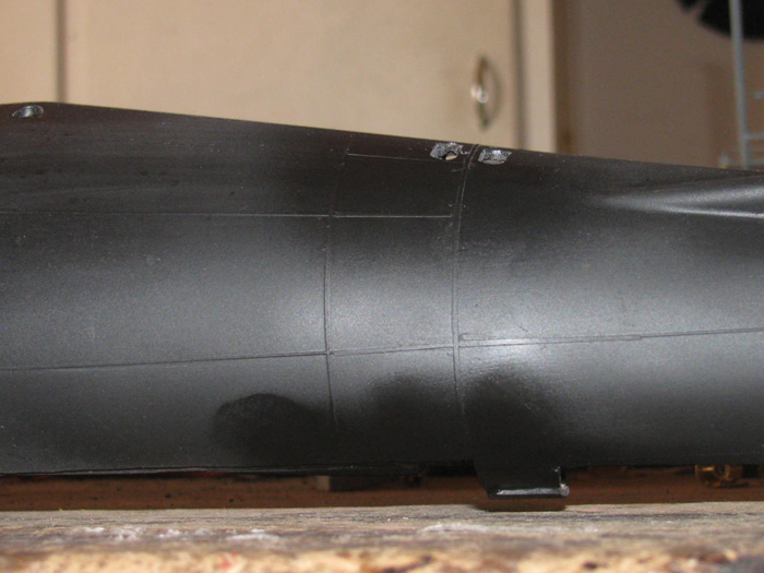
October 4th ===============================================
Painting the bottom fouling. No turning back now!
I started by brush painting the torpedo doors and propeller shaft bearings
with thinned down red oxide primer. (rust)
I followed that with a light red oxide over spray.
Then a light over spray of white.
I am going to let this dry then I will sand lightly with 400 wet/dry
to get rid of most of the heavy areas of white to let more red show through.
Final paint will be light misting of light gray over it all.
Followed by sanding to lighten up the coverage.
At that point, I want more black showing through in vertical streaks.
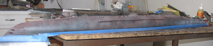
Rubbing out the first painting I sprayed a light gray misting over the
hull.
I don't llike the look at ths point.
The gray went on too heavy. (needed to be farther away)
But like when I did the GW, I didn't like it either.
After letting the paint dry for a day or two, I got after the paint
with 400 wet/dry sand paper and a little polishing compound.
In about 15 minutes I got the look I wanted or at least close to it.
So, on the Gato, I hold my opinion until the paint dries and I can sand
and compound it down.
I also think if it does not come up like I want, I can always mist
it with a little black and red oxide if I stay farther away when I spray.
Worse case, I start over by repainting the black.
Yea, painting. . . my favorite part of the build. . . NOT!
=================
I am having to readjust after having surgery on both eyes.
The issue is I can see things I could not see before.
Before I could see well enough to make things then finish them by touch.
Now I can see the things I couldn't before.
Better than touch.
This of course is causing problems for me.
Working on the Gato I now have to spend more time working on parts
to get them the way I want them.
The good part is the way I built things gets them really close and now
seeing I can gdo the finish a little faster limiting the touch method.
But the painting still looks bad to me.
Just as bad as before being able to see it.
The good part is, I do not mind being able to see the things I couldn't
see before.
And I bet those on the road like that I can see so much better now.
No accidents because I have always drove defensively.
I am never in a hurry.
If I start out late, I will be late when I get there.
But I am the type of person that hates being late.
So I leave early and will sit in the car in the parking until time
to arrive.
Anyway, I am seeing a whole new world.
To bad it doesn't change what some people are doing out there.
I do like living in the desert with my nearest neighbor 1/2 mile away
and at least that to the pavement.
October 5th ===============================================
I have been in and out of the shop today.
Started by lightly sanding the fouling I put on yesterday.
Seems to look better.
Got to where I can see the black paint under the fouling in places.
Got back to it later today and continued sanding with 400 wet/dry.
This was not to remove more fouling paint but to soften the sanding
line where the sand paper got a good bit instead of lightly touching the
paint.
After that, I spent some time buffing with the old tee shirt rag.
All of this was done going vertical so if the black was to show through,
it would have the look of water running down hill.
I took it out in to the sun to look it over.
I came to the same conclusion I did with the George Washington.
I can always sand more later if I find I do not like it.
Better than going to far and having to repaint. (nope)
While the tape is still in place on the waterline, I mixed some white,
Kelly green and a drop of thinner.
Mixed with the very small brush.
Got a light green but with streaks of white in it.
I painted a 1/8" to 3/16" line at the waterline.
I made sure the paint was thick in places and thin it others.
Even added thinner to a few brushes full of paint to get it transparent.
I will let this dry over night.
Then tomorrow, I will sand the green lightly like I did the GW.
This gets rid of the hard paint lines and blends it more in to the
fouling gray/white.
Before painting the green I went to the bow and stern and painted some
red oxide to look like rust again where the fouling paint covered it up.
Most of this will be sanded way.
I will get a photo or two before sanding down the green.
Then after I pull the tape.
I have been looking at the Gato for months on the stand under my tv.
With it's bright clean colors.
Having spent some time in the dry dock with the GW and the boat across
the dock in the other drydock, I know every after the new paint is applied,
it does not stay clean and bright for more than a few weeks.
The moisture in the air starts turning it dull and gives it streaks.
Once in the water and next to the pier, the green grass starts showing
itself in a week.
After a couple of weeks, the grass is 3" to 8" long.
From the waterline down it only grows about 18".
The rests starts turning a brown or gray color.
It is some sort of growth but not green like the waterline grass.
If I should not like the look, later I can repaint it back to the new
look.
The best part of this is I am not a rivet counter builder and good
can be anything I want it to be.
October 6th ===============================================
Photos as promised.
The bottom and green line have been sanded lightly.
The green looks like it may need more but I can do that later.
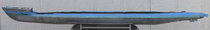
Pulled the tape and set the deck on the hull.
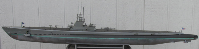
Put the propellers and shafts back in the boat.
Re installed the rudder and rear planes.
Starting to like the look.
The look outside in the sun didn't show the clean black hull sides.
Inside, the black looks so much better.
Still need to tone down the green.
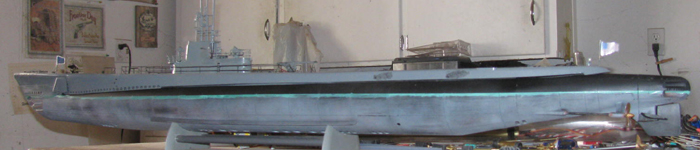
=========
While I had the paint out.
I thought I would fix the line on the George Washington rudder. (the
lower edge was angled and not level)
Here it is painted but not sanded to get rid of the shine.
The best part is, I saved the paper I was mixing the colors on for
the GW.
So I was able to match very close the shade of green used on the boat.
A couple of minutes with sand paper after the paint drys completely
will get the look to match the hull.
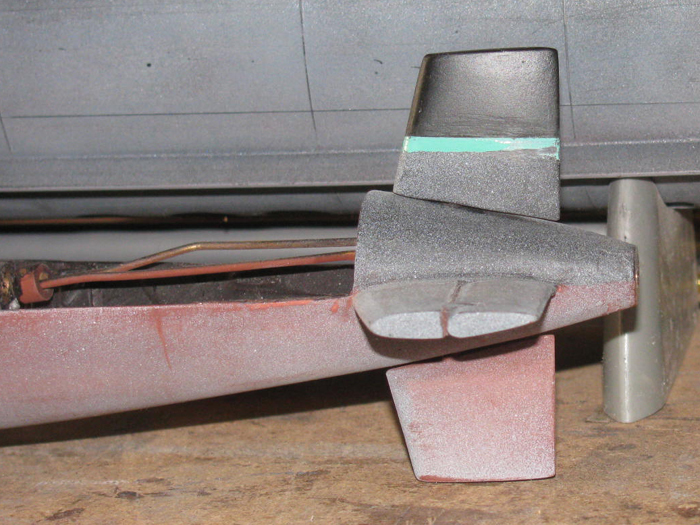
October 7th ===============================================
Today is one of those days where I do not feel like working on the boats.
Got other things to do
I was looking at the Gato transportation box.
The lid has been hard to set properly on the box.
Took the box out to the shop work bench and looked the box over.
There are 6 attaching screws.
3 of the 6 holes for the screws needed to be enlarged and cleaned up.
The screws were binding in the lid frame.
Exacto knife cut the bind nut holes bigger.
Then I used a file to open up the through holes in the box sides where
the screws where forced agains the box wood.
A little bit of work and the screws move freely in and out even when
I force the lid to each end.
Set the lid on the box and there is a 1/4" gap on one end.
It is this gap that had me take the box out to the shop in the first
place.
Move stuff over on the bench so I could sit the box flat on the bench
top.
The box itself has a slight twist in it.
End to end 56" there is a 3/16" lift on one corner.
I can fix this by taking the box out to the outside steel work bench.
Fill the box with scrap steel and lead to hold it down.
Put a 1/16" shim under the opposite corner and twist the box the other
direction.
As for the lids, I clamped 1 end to the bench and then I put a 3/8
plastic piece under the lids at the point the twist and bend start.
I slowly clamped the loose end down until both ends are touching the
bench top.
I am going to leave the lid clamped down for a few days.
I will check it each day and if needed, I will sand off some of the
paint and apply water to the wood frame parts.
The box I will put wooden boards to raise the weights so I can put about
¼ water in the box.
As hot as it has been for the last couple of weeks, the water will
get up over 105 F and this should allow the water to soak in to the wood.
With the clamps holding everything down, it should take the new shape.
The box should take 2 days to twist.
The water will be gone by morning then its a matter of it all drying
out.
If I can not straighten the lid, I will disassemble this lid or make
another.
October 9th ===============================================
I had a few minutes.
Out to the shop to check on the transportation box.
The lid is still twisted.
Changed the location of clamps and blocks and clamped it down again
Looked at the thread I ought to represent the antenna.
Upholstery thread.
Same size as sewing thread but much stronger.
I can't break it by hand.
Needs to be cut.
Sat down on my wooden milk crate.
Made a couple of brass parts for the front flag staff antenna bracket.
Soldiered the two pieces together after checking the tube part would
slip over the flag staff.
Using the exato saw, I put a notch at each end of the bracket.
The thread fits.
Did the same to the antenna brackets on the sizes of the conning tower.
I should be able to put about 1/2" of elastic thread on the ends of
the antenna to keep it tight and make it removable for transport.
The bracket I made slips over the flag staff and is glues on.
Once it cures, I will paint it gray and then put the tape back on the
union jack now below the bracket.
For about 20 minutes, this is what I got do today.
October 10th ===============================================
Woke up to high winds and dust in the air.
No painting.
No gluing.
That leaves working on the transportation box that I am trying to remove
a twist in.
I removed the lid from the work bench.
Looking it over, it needs more work.
But I need the box straight before I continue on the lid.
I have a 1/2" block under one side (right back)of the box and I have
two 25 pound bags of lead shot holding it all down on the bench.
Going to see if this will do it.
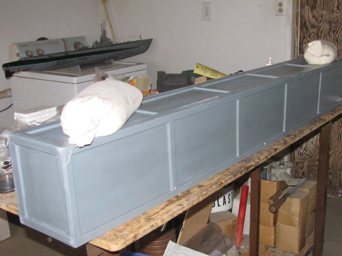
So no painting, gluing I thought I would finish the antenna on the bow
deck.
The attachment is not exactly what I had in mind.
It is all to small for my fat fingers to tie knots and loops in the
thread where I need them to be.
What I did was notch the support brackets on the tower just big enough
for the heavy thread to slip in to.
Then I tied several knots to get the look of the insulators and then
found the one I could pull the thread tight and have the bracket notch
hold it.
I was thinking to pull the thread tight put too much tension on the
flag staff and tower support brackets.
But then it came to me.
Hook one side of the antenna on the tower.
Run it through the flag staff bracket 2 notches and then back to the
tower.
Now lift up on the front of the deck causing the deck to bernd slightly.
This gave more slack on the thread to hook it up.
Lower the deck slowly and the antenna tighted up.
Set the deck on the hull and found the thread tension did not raise
the deck up off the hull.
Perfect.
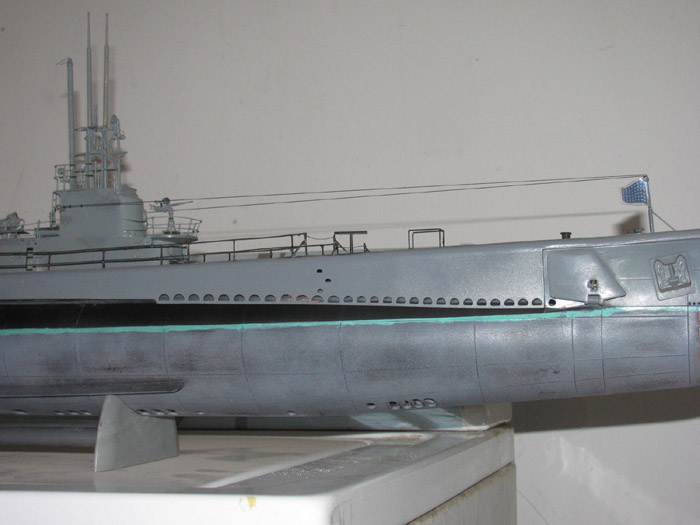
Now I am going in the house before the dust chokes me to death!
October 11th ===============================================
Had a few minites.
I retaped the front flag with clear water proof tape.
Trimmed with scissors to shape.
Removed the two 25 pound bags of shot from the transportation box.
Turned it over and looked to see it the twist was gone.
It appears to be very close to straight.
Straight enough to go back to working on the lids.
Put the lid on the box to see where the wrap is.
Still where it was before I started.
Found a scrap plastic block that is about 3/8" thick.
Placed it between the box and lid on the edge.
Put 25 pound bag on the far end and one on the close end.
I will let this it sit but I think I will have to move the far bag
closer to the wrapped spot to get more pressure to twist the lid.
I am trying to bend a 3/4" x 2" board with the 3/16" plywood panel and
1/4" thick by 3/4" wide framing strips.
Here is a photo of the lid during building.
The warp is on one edge. ( the farthest away)
About where the lid hangs off the work bench.
If I can not bend the lid frame board, I think I can make a thin saw
blade cut.
Then fill it with glue and clamp it back together.
The wrap is not a long bend but a sharp bend like there might have
been a knot in the board.
There are always options to fix things that are not correct.
October 12th ===============================================
The clamps and weights did not change the wrap of the lid.
Next option.
Cut the lid frame and and glue it after straightening the lid on the
metal work bench.
Here is the problem.
The lid will not sit down on the box top edge. (1/4")
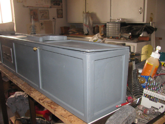
I cut all 4 four corners of the lid frame. (the long side at the corners)
I also cut the frame where there is a bend in the long side just past
the lid bolt.
Here you can see the cut near the lid bolt and then one in the corner.
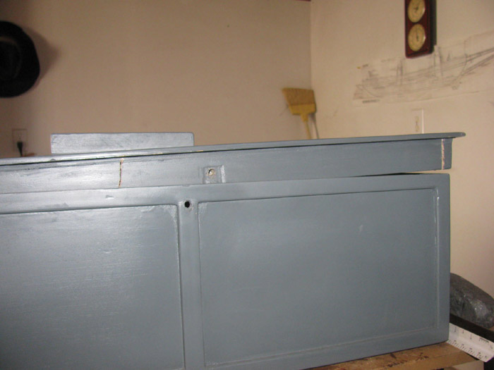
Before cutting the frame, I used the Dremel to grind in a slot for a
wooden biscuit.
Made a 1/4" thick biscuit to fill the slot.
Then I cut the frame to allow it to bend at the center of the slot.
This will straighten the frame long board.
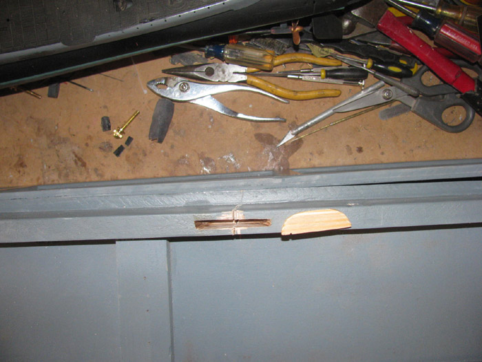
Here I dropped the biscuit in to the slot.
It stopped about half way.
Lightly tapping with a hammer drives the biscuit down flush.
The frame does not spread so I notice.
I will put the bisket in and let it cure before working the ends of
the lid frame.
With the end frames cut apart, the lid twists very easily.
I should be able to twist the frame straight and then glue it with
a 1/16" shim board.
Might use a few screws to hold it while curing them remove the screws
and fill the holes.
My transportation boxes have no nails or srews in them when completed.
(except for the hinges and name badges)
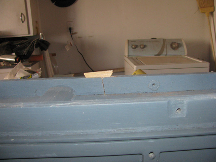
---------------------
The glue has been spread in the groove and the biscuit has been covered.
Biscuit has been hammered down in to the slot.
Wiped all the excess glue off.
Covered the slot and sides with clear tape.
Left 2 vent holes so the glue can expand.
Placed the lid on the box.
Weighted down (25 pounds) the end away from the gap.
I put a 1/16" plastic shim on the box edge before putting the weight
(another 25 pounds) 0n the gapped end.
Now to wait and see what happens after it cures.
October 13th ===============================================
The cut in the long side of the lid frame with the biscuit did what
it was suppose to.
The lid sits flat in the top of the box.
Sanded down the exposed edge of the biscuit to flush up with the frame.
Sanded the sides to remove the excess glue that expanded out.
Now ready for glazing.
Moved on to the 4 corners.
I made 4 plastic shims.
I started with 1/16" plastic flat sheet.
Using a Dremel sanding drum I sanded down each shim until it slipped
in to the corner notches with a little pressure.
Put glue on both sides of each shim and pushed them in to their cuts.
Used a small 8 ounce hammer to drive them all the way in and to flush
up the inside edge.
Turns out, I cut them correctly and there is no plastic shim exposed
when positioned center of the cut.
Clamped the frames so the expanding glue will not push the frame out.
If it does, I will run the frame edges through the table saw to square
them up and make them fit the box properly.
Will let all the glued parts cure before sanding.
So tomorrow looks like sanding and glazing.
Maybe even repainting the lid frame.
The wind has slowed down.
Weather says it should go down even more during the week.
This means I should be able to get back to the cylinder and close it
after a good clean up.
October 14th ===============================================
Today started at the VA eye clinic.
The followup exam on second eye surgery.
All went well.
No glasses needed. . .except I need to get reader glasses for 4' and
less distances.
Was give the numbers to get and told to go to drug store.
It will be faster than VA trying to make them.
Now at home, out to the shop I go.
Time to remove clamps.
You can see the plastic shim in the cut at the corner.
All four corners were done.
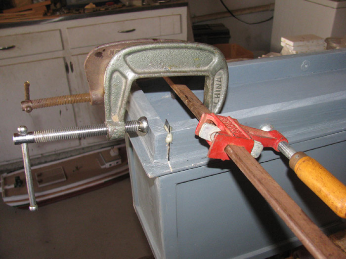
I have sanded the biscuit down flusk with the lid frame.
All the corners have been done.
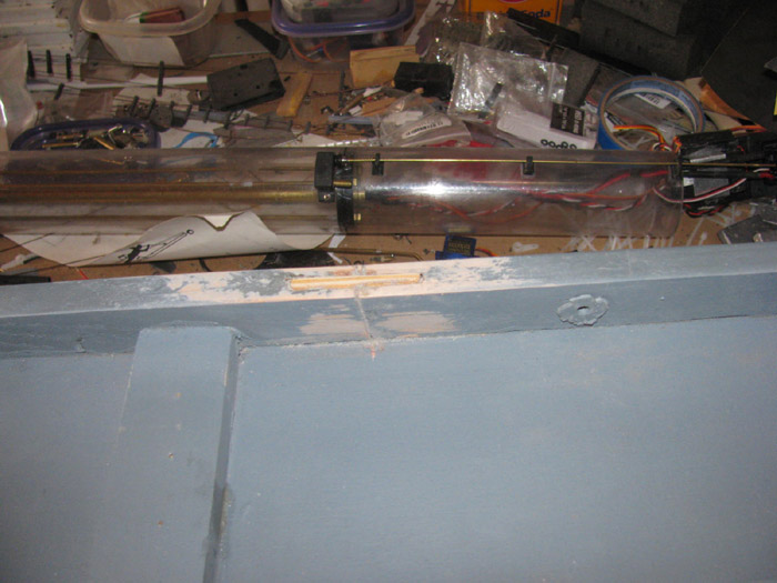
Here the biscuit cut has been glazed.
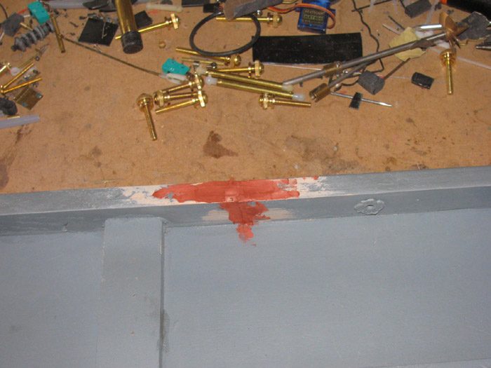
Here are 2 cornes on the end, glazed.
The other end has also been glazed.
(And yes, I test fit the lid to the box before glazing)
Sanding later today.
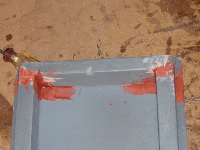
------------------
It is later in the day.
I have sanded the glaze.
Here is the biscuit cut mid frame.
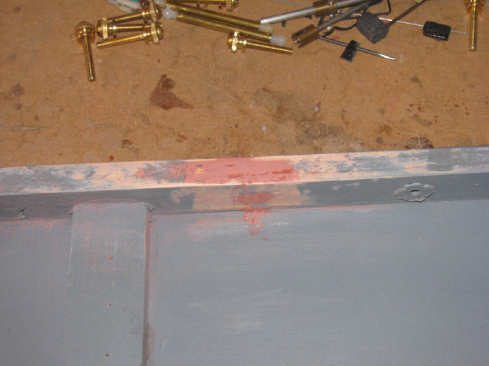
Corners.
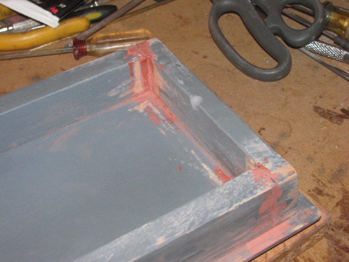
Corners at other end.
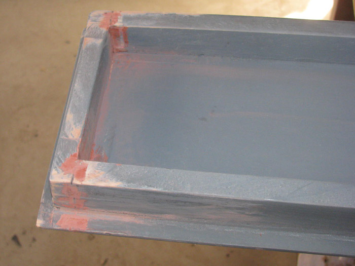
First coat of paint.
Over biscuit. (on this side of lid left of cross support)
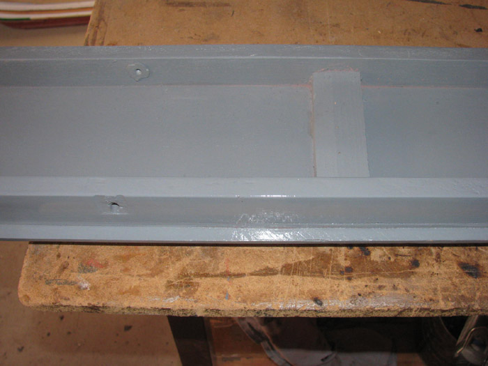
Corners.
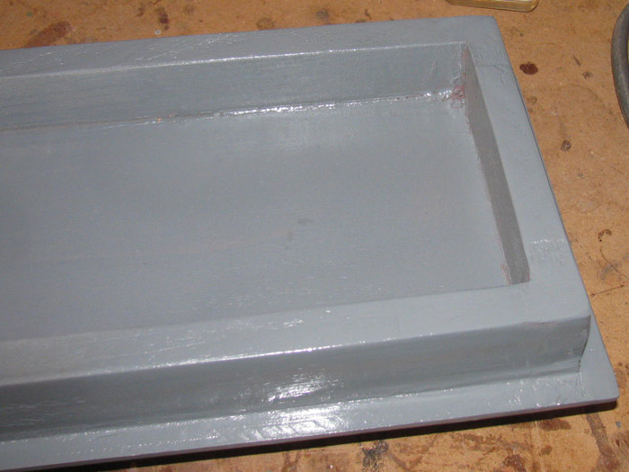
Other end corners.
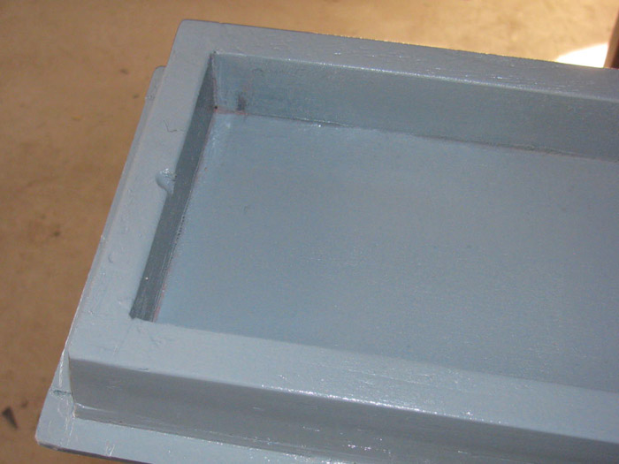
October 15th ===============================================
Second coat of paint on the transportation box lid.
The transportation box and lid are off the work bench.
Back to the cylinder stuffing.
Checked all the channels for correct operation.
Still good.
Slide the rear electronics tray in to the cylinder.
Pulled the excess wires in to the front section of the cylinder.
Slide the front electronics tray in.
Cleaning o-rings and cap grooves as I go.
Test the radio again.
All work but the vent/air pump control rod is dragging too much.
Disassemble the cylinder.
Remove the control rod to the vent.
Using the control rod, I put it in the through end cap bushing.
The control rod binds a little and not every time I move the rod.
Okay, I get out the 1/8" drill and run it though the bushing tube.
Try the control rod again.
Still a bit of binding.
Check control rod for straight.
It is.
Using a small round file I worked the inside of the through bushing.
Still a little binding.
Sanded the control rod with 400 wet/dry sand paper.
Getting better but.
Again with the drill bit.
Actually several times.
It now slides easily in the through bushing.
Reassembled the electronics tray.
Slid back in to cylinder.
Now What?
It is binding again.
Slid the tray out just enough to see both sides of the end cap.
It all works fine.
Okay, I looked carefully as I slid the tray back in to the cylinder.
I see the elctronics tray twist a little.
Maybe 1/32".
But the control rod now binds.
Okay what is causing the tray to twist?
On one side of the tray I have a shrink tube to push the excess wire
in to.
Not heated. Left soft.
On the other side of the tray, I have the Pitch controller mounted.
It contacts the cylinder wall.
So the Pitch controller and the wire tube, together are putting a lot
of pressure on the electronics tray.
I removed the pitch controller and slid the tray in to the cylinder.
The vent control rod binding stops.
So, I need to relocate the Pitch controller.
Might as well relocate the wire tube.
Out comes the Dremel with a grinding disk.
I cut the plastic bracket where the Pitch control was mounted on top.
I cut so the Pitch controller now sits besides the tray instead of
on top.
This required making a new aluminum Rx bracket.
I have mounted the new Rx bracket with Strong silicone glue.
No bolts or screws.
It has to cure before I can move on.
I believe I can mount the Pitch controller while the tray in in the
cylinder so I can center it in the open area.
I will use one of my short test cylinder pieces.
That way, I can get to both ends of the Pitch controller to move it
around and make sure it is level.
This new location will allow me to leave the Pitch Cocontroller mounted
and still get to the vent servo mounts, horn screw and the linkage without
removing the Pitch controller.
No more removing the Pitch controller to work ont he vent system. yea!
October 16th ===============================================
Looking at the new aluminum Rx bracket.
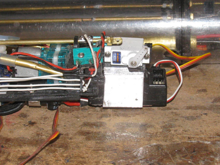
Checking placement of the Pitch controller.
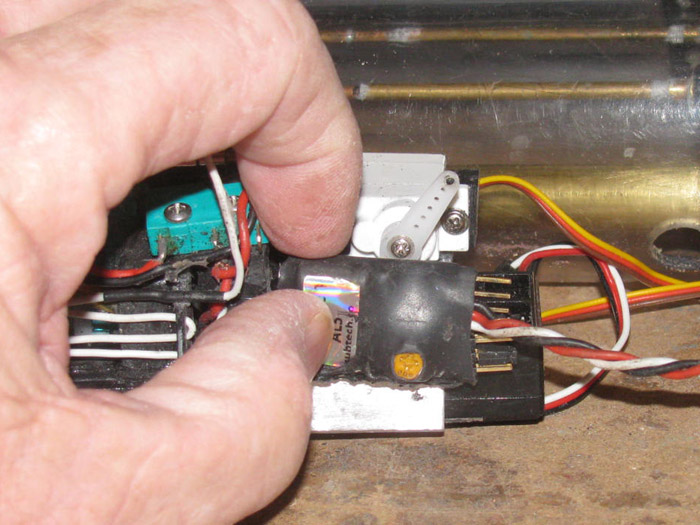
Making sure there is clearnce for the pitch controller using a short
test cylinder piece.
Looks like it will fit.
A couple of drops of black silicone glue and a rubber band to hold
it in place and it should work.
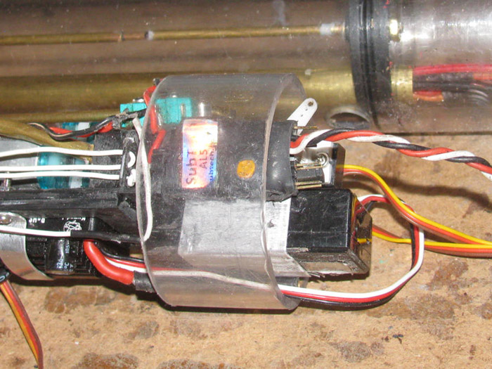
October 19th ===============================================
After a couple of days away from building boat stuff, maybe my interest
will get back on track.
Got stuff to do away from the house today but I did get in to the shop
for a few minutes.
Test fit the electronics tray in to the test cylinder.
It looks like I got the room needed for the ballast tank control rod
to move without touching anything in the cylinder including the cylinder
wall.
Plugged in the rudder, stern planes and ballast tank servos in to Rx.
Plugged in a battery to test.
They worked and I even got them on the correct channel.
I had to re run the antenna wire at the back bracket.
A drop of silicone will hold it in place once it cures.
Latter today, should I get back out to the shop, I plan to reassemble
the vent valve linkage.
Once connected, I can connect teh power leads and 2 servo leads to
the bow equipment.
Then I can slid the rear electronics tray in to the cyinder followed
by testing before installing the front electronics tray.
It is all going very slow but I do not have anywhere to be.
October 21st ===============================================
I am back in the shop.
VA eye stuff got in the way.
Everything is good.
Assembling the rear electronics tray, I am still having issues
with the ballast tank servo.
Remember I bought some metal gear servos in hopes of fixing the
issue.
This morning during testing the servo failed. . . AGAIN! 3rd one.
I opened up the servo to find 2 black gears which should have
been metal and are actually plsatic.
Not even nylon.
I checked all te ballast tank/air pimp control rod and linkage.
Everything is clear and not binding any where.
Okay, I will use one of the blue HXT900 servos I started with.
Reading the specs shows some differences.
The HXT900 is all nylon gears and has 1.6Kg/cm of torque.
The other one is plastic gears and 1.2Kg/cm of torque.
The servo change has been done.
Testing shows everything is working without binding.
I changed the servo arm location 1 gear on the spline.
This keeps the arm closer to 90 degrees to the control arm it
moves.
Bundled up all the wires and slid the tray in to the cylinder.
This requires pulling wires in to the front compartment.
Lots of wire.
Folded those wires until I could slide the front electronics tray
in to the cylinder.
Took 3 tried to get it all in.
Tested all the controls.
Tx to Rx.
So far every thing is good.
I can now put the cylinder back in the hull and finish the control
rods to the rudder, planes, bow retract and bow planes.
A matter of hooking them all up and cutting the excess brass
control rod overlapping.
I remember this was an issue during the previous trimming.
A lot of weight moving back and forth of the brass rods.
This will probably remove 12" of 1/16" rod all totaled.
The next few days, I have other things to do.
Including a much needed trip to the lake this Saturday.
My Skipjack and Akula II are both sea worthy.
The Akula II take less time to set up at the lake so I believe
it
will be the boat going.
I am looking at this coming Sunday to start trimming in the test
tank.
I have been thinking about making a lead keel to attach to the
bottom of the Gato.
1/8" thick. 3/16" wide. And the length of the bottom of the hull
straight center.
This should lower the GC and it will remove 1 lead weight from
inside the hull which is too high to help CG.
I found some 1/8" x 1/2" wooden boards.
Clamp them to the steel work bench and I have a mold.
Drill and pin with brass rod.
Should take about 15 minutes to do.
October 25th ==============================================
What to do today.?
I have a little time to go out to the shop.
The cylinder is assembled so I think I will put it in the hull and make
up the control rods.
Right now they are a little long so I knew I would have enough when
everything was assembled.
The bow planes and retracts are the easiest to get to.
Might as well start there.
With the Tx in hand, I operated the bow retracts to find full up and
full down.
Slid the wheel collor over both control rod ends.
These look good for length.
Did the same for the bow planes pitch.
These look good.
I must have set the length in the past.
On to the rudder and stern planes.
I know the rudder control rod is long because I replaced it a couple
of weeks ago.
The stern planes control rod is the correct length.
Just got to center the rudder and cut the 1/16" rod.
Done.
With the radios on, I adjusted the throw of each servo.
To keep from bending or breaking these control rods, I set the Tx to
20%, so all the controls are very short in throw.
Started with the bow retracts.
Physically centered the bow planes.
Move the retracts to full down.
Slipped the wheel collar on and adjusted the linkage and tightened
the set screw.
Operated the Tx to see how the tracts are set.
Centered the control knob and adjusted the planes to about 45 degrees.
Moved the control knob to full up.
On the Tx I adjusted the servo to about 55% which held the bow planes
adaginst the hull.
Moved the Tx control knob to full out.
Adjusted the Tx to about 53% which moved the planes to full horizontal.
Tested and this looks like it will work.
Connected the stern planes control rods.
Moved the planes to level and centered the control knob.
Tightened the wheel collar set screw.
Did the Tx adjustments until I got the planes to move about 30% degrees.
I do not use much rear planes angle because I do not usually control
them manually.
I let the pitch control run the rear planes.
Held the rudder control rod up to see where I should cut it for length.
I cut it about 1/8" short.
Not a problem because I overlap the control rods about 1/2".
Centered the control knob and centered the rudder.
Tightened the set screw.
With a small file, I mark the control rods so I can dulpicate the location
during assembley and disassembly of the boat.
Everything but the propeller shafts are installed.
I did some control testing.
Everything works fine except!
The main motor is binding and stops at slow speed.
Then I have to turn everything off to reset the system.
Tested thsi a few times.
I have to find why it is binding.
This means. . . Yep, remove and disassemble the cylinder to get a closer
look inside.
Right now on the work bench the cylinder is disassembled and the main
motor works fine.
So when in the cylinder, there is something putting pressure on the
electronics tray bending it enough to bind the motor shaft.
Or maybe the end cap is binding the shaft when in the cylinder.
I thought I had isolated the motor and mount from the electronics tray.
Or when I put the tray in the cylinder there are wires that are lifting
the tray up do to bunching under the tray.
Got to find the problem and fix it.
It will not run this way.
October 27th ==============================================
This afternoon I got to look at the Gato cylinder, looking for the reason
the main motor binds up when everything is in the cylinder.
With both electronic trays out of the cylinder, I tested all the controls.
Paying attention to the main motor.
The motor runs with no effort at all in both directions.
Next, I put the rear electronics tray in to the cylinder.
Interesting!
The main motor runs in both directions with no effort.
The only thing different from when I tested it the other day is I have
not connected the cables that hold the two end caps on in case there is
a pressure build upp in the cylinder from the air pumps.
My next test will be to put the front electronics tray in the cylinder
and test it again.
If the main motor runs then I will put the cables on the cylinder.
If the motor binds, then there has to be something caused by the cable
straining on the end caps.
The rear end cap has 2 screws that stick up so I can put the cable
loop over it and hold the cable.
What I think is happening is this.
The gear box is not square to the end cap and has a shim under one
side to hold the gear box off the end cap about 1/32"
This squares up the gear box shafts tothe main shaft coming through
the end cap.
I think the cable strain is pulling that side of the end cap down.
This would cause binding.
I have several options to fix this.
Use a large surface shim so the end cap and not move under cable pressure.
I can take the gear box off the end cap and cover the gear box with
a full shim and sand it down until the gear box is in full contact with
the end cap.
I can change the location from where the cable attached to the gear
box to the sides of the end cap.
I can measure the needed cable so it fits better with no pressure unless
an end cap moves out. (look and see how much o-ring I have)
I think the best fix would be to make a full size shim and sand the
angle in to it.
Then make the 2 new cables with less pressure on the gear box.
I will look at the gear box and see why the shafts are not square to
the box face.
Might be easier to re design the gear box with cut outs for the cables
going to screws in the end cap which would put no pressure on the gear
box.
Making new cables will be a good thing.
I made the originals from scraps which put a slice near one end of
the cable.
The splice joint always hangs up when dropping the cylinder in the
hull.
Requires me to drop the cylinder in at 90 degrees then turn it once
past the hull top edge.
October 28th ==============================================
Removed two rubber control rod boots.
Removed the 3 gears from the gear box.
While I had the gear shafts in hand, I cleaned up the ends of the shafts.
They were not truly squared up.
Removed the 2 cable anchor screws. (not shown in photos)
Removed the 2 gear box mounting screws.
Now I can put the gear box on and off to look for the end cap to gear
box problem that lets the gear box move or rock as the cables are put on.
The third time I slipped the gear box on to the propeller shaft, I
noticed one of the gear box sides moved.
The mount moved towards the center.
With the gear box bracket in hand, I closely looked over the part.
This is a photo of the gear box mounted on the end cap while I was making
the end cap holes for the control rods and air inlets.
I found a crack on the other side next to the cap.
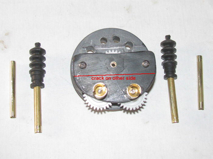
So, I am building a new gear box using aluminum with plastic spacers.
I have cut the aluminim out of my old trusty 25 mph sign.
I made 4 pieces, 1.25" x 2.25" x 1/16" thick.
I will be doubling up the pieces. to get 1/8".
After sanding both sides of each piece, I have applied glue and the
pieces are in the vise for over night.
I find Gorilla glue will bond aluminum very well if cured under pressure.
I have in the past made sail boat keels this way. (Some are 30 years
or more old)
I did some grinding on the original plastic gear box.
I have a new shape which will allow me to put the cables on the end
cap and not the gear box.
The cables will attach under the gear box mounting screws, just above
the drawn crack line.
I also think I have come up with brass ends for the cables that will
have a 90 degree bend and will not put pressure on the end caps unless
the end caps move to come off.
Anyway, I have a plan in motion.
October 29th ==============================================
Out to the shop to see what I have.
Yesterday, I started by cutting a piece of aluminum from my 25mph street
sign.
Marked up for cutting 4 smaller pieces for the gear box bushing supports.
Original gear box sitting on top of aluminum to make sure I cut the
pieces big enough.
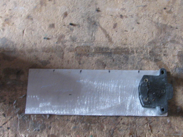
After cutting, I applied Gorilla glue and stuck 2 pieces together.
I will have 2 pieces, 2 layers thick of 1/16" aluminum to work with.
Placed them in the small vise to put pressure on the pieces.
Place clear packing tape between the vise jaw before placing the aluminim
pieces between the jaws.
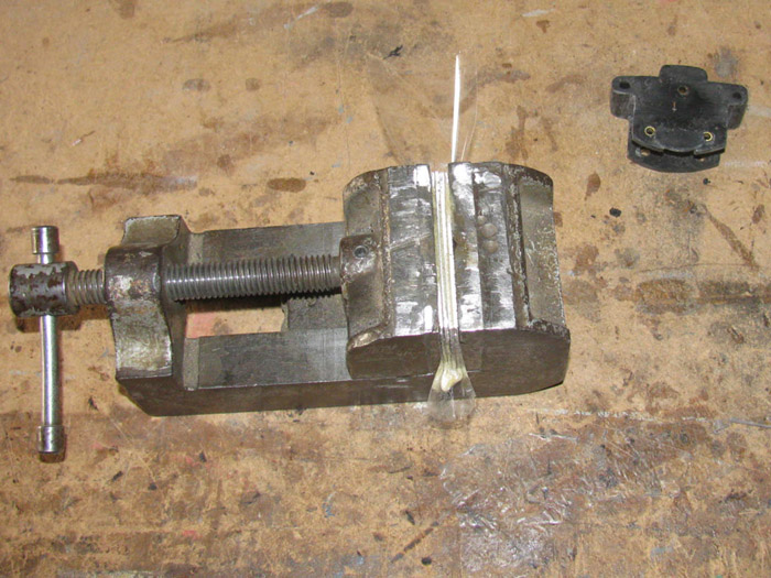
Took the aluminum pieces out of the vise.
The glue is still sticky.
Cleaned off the excess glue and place back in the vise.
It is going to take a little longer to cure.
It needs to be completely cured before I can start drilling holes and
grinding to shape.
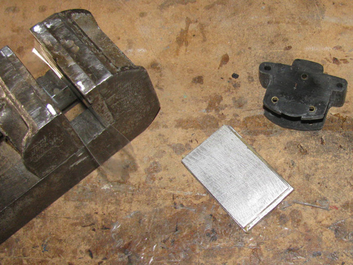
The glue curing is going to take some time.
What to do?
Make up the new cables.
I am going to need 4 end eyes.
I used a length of 3/32" brass tubing.
I slit the tubing witht he Dremel cutting wheel. (the one they
call a diamond wheel)
I opened up the tube at the split.
Hammered it flat and punched a center mark for the drill.
Out to the tool shed and drill the end holes.
In the photo you can see 3 of the eyes. The 4th is on the other end
of the bottom tube.
You can see the 2 pins I made to hld the cable to the front end cap.
I am thinking I will screw the other ends to the rear cap with the small
bolts.
That will remove the screws I was hooking the cable loops over.
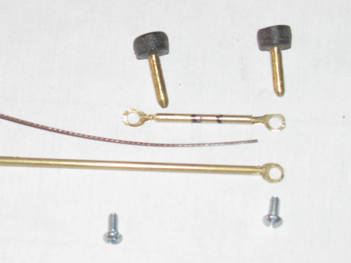
Made up 2 ends for the front cap.
I will cover with heat shrink tube when I get ready to make the stern
end.
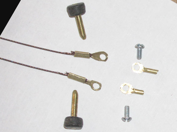
October 30th ==============================================
The gear box plates glue has cured.
Time to drill holes for shaft bushings.
I started by sitting the original plastic gear box on top of one of
the aluminum plates.
Marked the propeller shaft hole.
Punched a dimple and off tot eh tool shed to drill that hole.
The hole size is for the bushing which the 1/8" stainless shaft goes
through.
The brass tube is the bushing material.
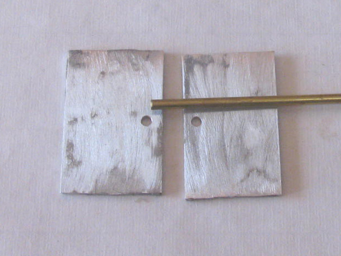
I placed the original gear box on the new plates.
I pushed a short length of brass tubing through the propeller shaft
hole.
I marked 1 gear location hole and drilled it.
I drilled through the existing bushing with a 1/8" drill bit.
I put another drill bit in the hole to hold the gear box in line with
the plates. (i was drilling both plates at once)
I did this with the mounting holes as well.
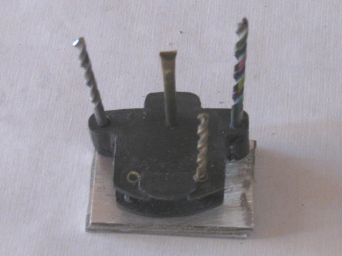
I made 6 new bushings.
They are long and I used a small Phillips screw driver to spread one
side of the bushing.
On the left plate the bushings look square from the screw drive punching.
I will be gluing these in lace and making the punched side flush with
teh late.
I set the 3 gears in place with shafts on the right plate.
I wanted to make sure the gears met properly.
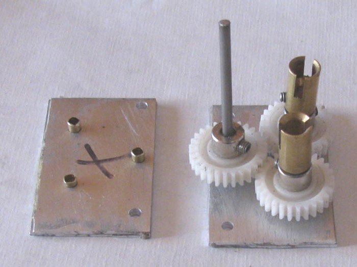
A straight down photo shows the gears that meet and where they do not
meet.
The propeller gear looks like it might not meet but that is the shafts
at a slight angle.
With the second plate in plate the gears tighten up.
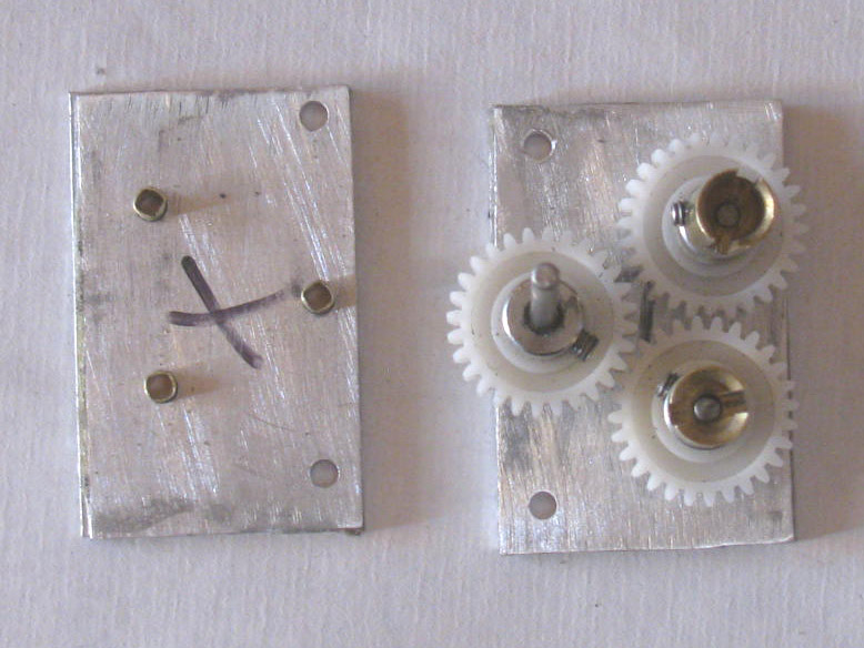
Next, I need to make 3 plastic spacers that will hold the plates the
correct distance apart.
October 31st ==============================================
The 6 bushings have been sized for length.
The holes in the aluminum plates have been beveled on both sides to
get a better glue hold.
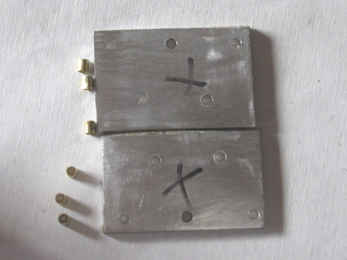
Glue applied to the inside of each hole.
Glue was also applied to the outside of each bushing.
Then the bushings where hammered in to the holes until flush with aluminum.
(other side with X)
The flush side will be the side the gears are against.
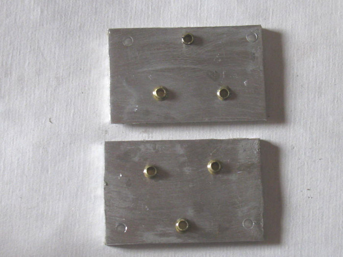
The 2 propeller shafts and the main motor shaft have been inserted in
to the bushing to align the bushings for smooth turning.
Clamped the plates in the small table vise.
As I tightened the vise, I continued to check the shafts for smooth
turning.
Then the C clamp was put in place to hold the plates tight.
C clamp in place and the 3 shafts all turn smoothly.
Now to let the glue cure.
I put silicone grease on the 3 shafts to help keep the glue as it expands
from bonding to the shafts.
I also smeared silicone grease on both plates where they come together
at the shafts.
The hope is the plates do not bond to each other and the shafts can
be turned out without removing the bushings.
November 3rd ==============================================
The gear box mount has been shaped.
Both sides of each bracket has been resanded to clean up the glue.
The inside of all bushings have been cleaned for smooth turning of
the shafts.
I made 2 plastic spacers to hold the brackets the correct distance apart
for the gears.
Turns out, I can make the spacers wider for more bearing surface.
I cut up more plastic pieces and glued them together and put them in
the vise for pressure.
Again waiting for the glue to cure.
Moved on to painting the gear box brackets.
Thought I would place the gears on the bracket with the propeller shaft
and mounting bolts.
The gear fit is good.
Very little lash between the gears.
It also looks like I might be able to use the bracket to end cap mounting
bolts as the safety cable connection.
This would put the cables on the cylinder center line.
I check this in the next few days.
November 7th =================================================
Finally back to the gear box.
I rough shaped the 2 plastic spacers.
Drilled the holes for the through bolts.
Using the propeller shaft and 2 gear shafts to hold the mounting brackets
inline, I glued the plastic spacers to the brackets.
Clamped to cure.
After camping, I made sure the 3 shafts turn easily and smooth. (all
good)
The glue holds the spacers in place but the bolts hold it all together
for strength.
After the glue cures, I will finish the shaping of the plastic spacers.
November 8th =================================================
Got up this morning to frost and a little ice on the ground.
So I got a late start about 10:30am or 11:00am.
First thing I did was check weather for tonight.
Says a possible hard freeze.
So it is time to check the heater on the water pipes where they come
in to the house.
This took all of about 10 minutes.
Everything is ready for winter freezes.
Out tothe shop and work on stuff.
I trimmed the excess glue from the earrbox.
Removed the clamps and then removed the shafts and gears.
I needed to trim glue from the inside of the gear box as well.
Proceeded to shape the plactic spacers to the edge of the aluminum brackets.
Cleaned out the bushing and drilled the holes through the spacers to
make the straight with the brackets.
Cleaned up the shafts by spinning in the Dremel and 400 wet/dry sand
paper.
Everything turns smoothly.
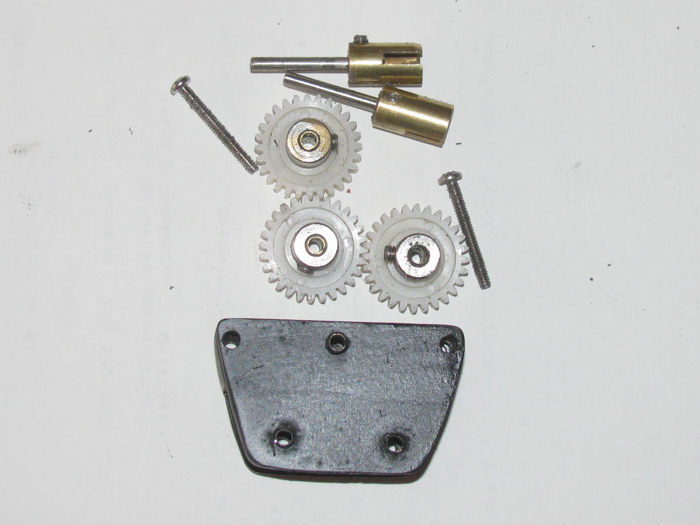
Repainted the gear box.
Cleaned the paint out of the bushings.
A 1/8" round file makes the job easy and quick.
Assembled the gear box.
Ready for installing on the end cap.
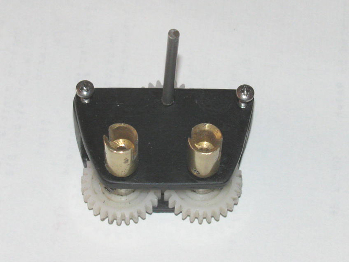
While I was waiting for the paint to dry on the gear box so I could
assemble it, I took my small bench vise apart and cleaned it up.
At this point, I might as well paint it.
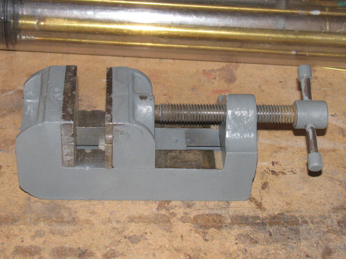
November 10th =================================================
Today I fitted the gear box to the end cap.
The holes I drilled in to the gear box did not match up with the holes
in the end cap.
They were off just a little.
Using the 1/8" round file, I slowly filed the gear box holes bigger
until the bolts lined up with the holes in the end cap.
The holes are oval in shape now but they allow the bolts to go through
without binding.
Before I mount the gear box to the end cap, I need to disassemble it
so I can clean and grease the cup seal where the main propeller shaft comes
through.
******************************************************
******************************************************
February 24th =================================================
A quick note:
Work on the Gato stopped last November because I ran my Akula II at
the lake and ran the batteries down to where the speed controller/BEC shut
off.
The Akula was stranded out about 150' from shore and there was no wind.
I usually take more than 1 boat but this day I only had the Akula.
I sat in my chair waiting for the wind to come up and hoped it came
up blowing towards shore where I was sitting.
\If it had come up 180 degrees it would have been over a mile to walk
to the other side of the lake.
I got lucky and the wind slowly came up towards near me.
A 100' walk.
While sitting there waiting, I thought I should have brought 2 boats.
Usually there are others there with boats that could have pushed me
in.
But this day I was alone.
Another thought was to build a rescue boat of some sort.
This is what I did.
I built a Rescue Barge.
Started the build on Nov 14th and the barge is now complete except
for waiting for a new motor and servo.
Yesterday, I put the barge in its transportation box for protection
and cleaned off the work bench.
This morning the Gato was put back on the bench and work has now resumed
on the Gato.
I remember having to drill a hole in the rear end cap for the cylinder
safety cables.
I got the cylinder on the table and cleaned all the dust off of it.
I put the end caps on the cylinder so I could try to remember what
I was doing with the safety cables.
The good news is 1 cable was made and all I had to do was make up the
second after drilling the hole in the end cap.
I have to make a brass tube end piece that the gear box screw goes through.
Here is a photo of the two I made just before stopping work.
When I bent them over to get past the cylinder sides, one broke so
I had to make a new one.
Not a big job. (about 5 minutes)
The hole I driller as too deep and I had to fill the bottom.
The glue is now curing.
After making up this part, I sorted through the parts on the bench and
found most if not all the parts to assemble the cylinder.
When I put the end caps on the cylinder to measure the cables, I realized,
I need to learn how it all goes together in the cylinder.
There is no extra space and if I do not get the equipment lined up
right, it will not fit.
The Gato was ready for water trimming after the safety cables where
made.
So, I should be very close.
April 17th =================================================
The Barge is finished.
The Skipjack is repaired.
The work bench is ready for the Gato.
I moved the Gato back on to the work bench.
I have sorted out parts sitting on the bench and in 2 plastic boxes.
The Gato was stopped while a new longer ballast tank was being installed.
The tank was installed but the linkage was not.
April 18th =================================================
Finally in the shop just after noon.
I started placing the ballast tank vent parts on the bench to make
sure I had them all and I had them in the correct order.
Long brass rod, 2 wheel collars with stainless grub screws, 2 ball
point pen springs and a plastic piece made to go on the servo control rod
and turn the force 180 degrees on to the vent control rod.
The vent valve seal assembly which holds the o-ring seal.
I got the vent valve control rod on the cylinder.
I was turning the cylinder over to look at the alignment.
Good thing I did.
Looking through the cylinder through the bottom, I see 1 wire connector
with no connected plug.
I found it.
It is stuffed near the front of the rear compartment.
Something I did to make it easier to put the cylinder in and out while
fitting the new ballast tank frame.
Okay, I will need to slide the electronics tray out of the cylinder
and check all the wires and make sure they go where they are suppose to
go.
Removing the rear electronics tray requires pulling the front electronics
tray to straighten out he 2 servo wires and 2 power wires so they will
slide through the brass tube through the ballast tank.
Getting all that wire in the front compartment is a pain.
It has to be done.
May 25th ===========================
Finally back in the shop after the barge build.
I am going through the electronics trays.Making sure all connections
are correct.
I have put the rear electronics tray in to the cylinder.
Pulled the wires through the ballast tank and I connected the plugs
to the front electronics tray.
Every thing was tested and every thing works.
I have the front tray out of the boat to charge the batteries.
The Tx is also on the charger.
I thought I got LiFe batteries for the Tx.
I will have to look.
I have run in to a problem.
The tape that holds the 2 battery packs in the tray has pulled the
battery labels off.
I do not remember the numbers on these batteries.
How can I figure out what they are?
If I can get the batteries charge in the boat, I should be water testing
tomorrow.
----------------------
I decided to take the batteries out of the tray and remove the tape
holding them together.
Surprise.
I had placed the batteries for the battery information of both batteries
were facing each other.
I only lost the scanner code bars.
So, I have the battery info needed to setup charger.
----------------------
Once I setup the charge correctly, I now have 2 charged batteries for
the Gato.
Looked around and found a LiFe Tx battery on the work bench under a
lot of parts and tools.
Put it on the charge only to see the battery was fully charged.
I know this battery has to have been on the bench for 4 months or more.
(that's when I bought these LiFe batteries)
Tomorrow, I will wrap the 2 batteries and install on the front electronics
tray.
Hookup the 6 plugs and test the system.
If it works correctly, the front electronics tray will be slide in to
the cylinder.
The tray is mounted on the front end cap.
This will seal the cylinder and I can put the cylinder in the water
to test for leaks.
If good, then in to the hull and connect all the controls for trim
testing.
When I stopped working on the Gato to build the Rescue Barge, I remember
I was close to trimming again with the new larger ballast tank.
The boat had been trimmed but I did not like the waterline and submerged
trim.
Not enough volume, so I added 1" to the ballast tank.
I hope to have too much tank volume.
I want to get full surfaced waterline.
And when submerged the boat should sink.
The ballast system is a snorkel system.
I need the one mast that is the air tube to be above the surface.
My plan is to put enough foam in the conning tower to stop the boat
from going negative and have about 1/2" of the conning tower above the
surface.
I can change this foam block after I get a good waterline and the front
planes should drive the boat to periscope depth.
I do not need more than that.
I also want the boat to come up to this 1/2" of the conning tower above
the surface when I stop the main motor.
I chose this system because I was using parts I had in the parts box.
And there just isn't much room in a 2.5" cylinder for much after the
ballast tank size needed.
6 servos, ESC, motor, pitch controller, batteries and other stuff like
wires and plugs.
May 26th ===========================
Like always, other stuff got in the way.
But I got about 30 to 45 minutes in the shop.
I installed the charged batteries.
I connected all the wire plugs.
Got the Tx out and tested all controls.
All looked and operated correctly.
Folded the wires and slowly slide the front end cap in to the cylinder.
I cleaned and grease the cap o-ring before finally sliding the cap
in to the cylinder.
Made up the 2 safety cables that go from the rear end cap to the front
end cap to hold them on.
They can not slide out far enough to break the cap o-ring seals.
Other things are still happening so there will be no water testing today.
But the cylinder is ready.
May 27th ===========================
Water test tank was filled.
The cylinder was assembled completely.
I almost forgot the rudder and rear planes boot seals.
I have a fuel hose with a fitting to put on the front end cap which
has a Schreader valve in it. (no internals in valve)
Once the cylinder is in the water completely submerged, I can blow
lightly in to the fuel hose creating a positive pressure in the cylinder.
If there are any leaks, I will see bubbles.
Okay here goes. . . . I see bubbles coming from the rudder boot at the
exit end.
I also see bubbles coming from the air to pump inlet and outlets. (not
much)
If I lighten the pressure these bubbles stop.
So I will work on the rudder boot leak.
I removed the boot on the control rod.
I see what might be causing the leak.
On the bottom of the control rod there is a small amount of soldier.
I must not have files it down to the brass.
With a fine small file, I removed the soldier and sanded with 200 grit
paper.
Reinstalled the boot and back tot he water tank.
No bubbles from the rubber control boot.
Still there are the bubbles from the air pump inlet and outlet.
Lower the pressure and they stop.
Now considering there is not pressure in the cylinder when operating.
With the cylinder in the water and no pressure being applied, there
are no water leaks in to the cylinder from the air lines.
Next I need to put the cylinder in the hull and hook up all the controls
Put the boat int he water and run the systems to see if they all work
in the water and watch for leaks in the air system.
What I can do is put a little pressure in the cylinder as I close it
up.
With positive pressure in the cylinder, it should keep water out.
If the water does get in through the air system, it means removal and
rebuild of the air system. (yuck)
Right now the cylinder is drying.
I am breaking for lunch.
After lunch I will put the cylinder in the boat and ready it for the
water tank.
I put the cylinder in the hull.
Hooked up the air hoses.
Checked all controls.
Out to the water tank.
In to the water and this is when things started going wrong.
First the motor would not turn the propellers.
Lifted the deck off to see inside.
The propeller shafts seem to be binding.
The angle from gear box to propeller shafts is to great.
Continue on with testing.
Dive planes retract/extend failed to come up.
Down okay but up I could hear the servo gears jumping or stripping.
(Know problem with these servos. I have lots of them)
Air pump is not adjusted correctly.
Only 1 pump comes on and when the control is moved for both to run,
it did not happen.
This is an adjustment on the control bar in the cylinder.
All but one items is a matter of adjustment and replacing the bad servo.
The propeller shafts will require modifying the gear box and main motor
location.
This may require the building of a new rear electronics tray to move
the motor.
I will disassemble the cylinder and get the rear electronics tray out
of the cylinder.
I am wondering if I were to move the motor down and turn the gear box
180 degree, would the propeller shafts be more straight?
One more thing.
The ballast tank 1" extension did not give me the waterline I wanted.
But that may be just a trimming issue.
The extension went forward and I may need to move weight forward to
compensate for the extra buoyancy to lift the stern.
I will go after these issues one at a time.
The propeller alignment will be fist and require the most modification.
One thing I learned that no one could tell me, was, can these little
air pumps pump water as well as air.
First time int he water tank, I had the air inlet and outlet reversed.
I recieved an unexpected shower from the 4 small holes in the mast
that is my air intake.
I was wonder because if I were to run the boat and the inlet go under
could the pumps pump the water through and then followed by air.
The answer is yes, though I hope not to make this a normal running
procedure.
Last point.
There is no water in the dry sections of the cylinder after an hour
of testing.
One safety cable needs to shortened a little.
Since testing earlier today, I have been thinking about this boat.
The hull went together rather quickly.
But the stuffing of all the electronics and pumps and servos and ...
and ... and is beating me down.
Everything I try seems to work on the bench but as soon as it goes
to the test tank, it either works poorly or not at all.
I have been fixing things that don't work right for more than a year.
Still I am no closer to being done than the day I started this build.
I even took time away from it with the hopes of coming back with more
energy for it.
I am not giving up just yet.
The boat would look good on a wall shelf.
I have things to do tomorrow so I will not let the boat worry me.
But come Saturday, I think the plan will be to remove everything from
the cylinder and start over.
The 2 servos in the front could use better alignment through the end
cap.
All the wiring could use better routing through the cylinder. (there's
just too much to stuff in the forward compartment)
The rear compartment will need to be completely disassembled.
I need to get the propeller shafts and the gear box in a more straight
line.
This will require moving the main motor.
The 2 air pumps need a better manifold or I need to come up with a
different ballast system all together.
So, I need to go at it as if I had not built any of it.
Maybe a 3 piece cylinder so I can get a bigger section for the ballast
tank which could be shorter giving me more room in the front and rear electronics
sections.
This might allow me to make a piston system. (I have space for the
long threaded rod if the motor is mounted lower)
I will make hard paper card mock ups before cutting and shaping aluminum
trays.
If I remove the off/on switch, I could get 3/4" more free space in the
front compartment.
----------
I might try batteries in the wet and move them under the bow deck in
front of the planes mechanism.
That frees up 3" in the front compartment.
Until I get started on the new build, I don't know how I will put it
together.
The quick fix would be to remove everything but the motor and rudder
controls and make it a surface boat.
Kidding......If it is not a submarine, it is a wall hanger.
Sorry, frustration hit me this afternoon.
I need photos of your working Gato cylinders.
I need to see what works and how it is placed in the cylinder.
I have read so many Gato builds, I just don't want to do that again.
May 28th ===========================
Got done earlier than expected today. (doing other stuff)
Out to the shop and disassembled the rear electronics tray.
I wanted to see if I could straighten the propeller shaft to gear box
angle.
The answer is, Maybe.
I will need to move the motor through the end cap down about 3/8".
As the gear box is made, I can not move the motor and get the full
3/8" drop.
The motor would sit on the cylinder wall.
Now I measured everything and I think I can do this if I change the
gear on the motor shaft.
It is 28 teeth gear.
I ordered a 12 and a 14 tooth pinon gear.
I hope this will give me the room needed.
I looked at the air pumps to see if I can change the the inlet and outlet
locations.
Part of the air leak is that I have the air in to ballast tank at the
top of the tank.
When the pumps are off, the water pressure in the ballast tank is pushing
air back through the pumps.
If I have room I could probably use a check valve in that air line.
But if I move the hose so the end of the hose is at the bottom of the
ballast tank, the pressure in the ballast tank will not push air out the
air hose.
To do this, all I have to do is run a 1/8" brass tube from the end
of the end cap where I can connect the air outlet in the end cap to this
brass tube and the other end will end with a 90 degree piece so the air
will bubble up through one of the ballast tank flood holes.
I made the holes a little too big and will be putting a piece of plastic
over 2 or the three to make them smaller.
I need to pressure check the air pumps.
Put a fuel hose on the inlet and blow through it lightly and see it
the air leaks out when I plug the outlet with my finger.
If this test shows no leak, I can use the original rear end cap instead
of making a new one.
Just fill the original motor shaft bearing hole and drill a new one
once I get the new pinon gear.
Looking at the electronics tray, I see I can move the 2 servos rear
word and make the tray 1/2" shorter.
I do not remember building the rear electronics tray in 4 sections.
I can move each section up or down with shims as needed for height.
I guess when I was build the tray, I was planning ahead to access problems.
When I removed the rear tray, I have to remove the front tray to get
to the wire plugs.
I can save room by changing the main power wires.
They are 18 gauge but they are also silicone insulated.
This makes for very thick wires.
I am going to get some 22 gauge stranded wire with standard insulation
and see if this helps with folding the excess in the front compartment.
I reread my original build and trimming.
I may have over looked trimming process.
In the water the bow is high and the stern is low by 1/2".
I think I left out a movable ballast block that goes up near the bob.
Pushing the bow down will bring the stern up.
I found the ballast block on the bench.
It is marked bow block #1.
Seem like it should be in the hull.
I also had a slight roll to the side during surfacing.
This block would also help that problem.
I got a lot done in 1 hour in the shop.
Got to find another hobby shop.
The one I used for years closed and moved.
Don't know where it went yet.
Anyway, progress continues.
May 29th ===========================
In to the shop to get after the Gato issues.
With the rear electronics tray disassembled in to 3 sections, I can
measure parts as needed to modify the trays.
I started with the motor and gear box.
The gear box will be turn 180 degrees to get the main motor lower in
the cylinder but more importantly, I need the 2 out put shafts for the
propellers to come up higher than they are.
The angle was just too much for the dog bones.
Well the measuring tells me I can not use the original end cap.
The 5 brass tubes coming through the end cap can not get past the gear
box.
Beside, I have 2 small pinon gears coming which will help move the bear
box down.
I did measure the motor and the cylinder clearance so I could drill
the end cap for the motor bearing.
Using a short piece of cylinder, I can get in there with a pencil to
mark the end cap and motor shaft position.
Drill the end cap for the shaft which leaves a little room to file the
hole in any direction needed when I file the hole bigger for the bearing.
Turns out, I hit right where it needs to be.
I put the motor shaft extension through the end cap and slipped the
gear box on the shaft.
Before I drill holes for the control rods and air tubes, I will wait
for the smaller pinon gears.
Next, I worked on the second tray inline to move the servos.
What this did was remove a gap of 3/8" between the motor end and the
air manifold.
This was a matter of cutting a little plastic off the tray allowing
the servos to move closer to the manifold.
When I start assembling every thing, there will be a little more removed
from the aluminum part of the tray when I know exactly where the motor
ends up.
Third Item.
I woke up this morning with a thought on how to plumb the air from
the read end cap to the ballast tank.
My air leak was because the pressure in the ballast tank full of water
was push back through the pumps.
So, the though is to bring the air in from the bottom of the ballast
tanks in one of the flood holes.
I will use brass tubing (5/32" id) running in the bottom of the hull
on the keel center line and make a 90 degree turn up under the flood hole.
The back end of the tube will be turned up about 45 degrees so I can
slip the rubber fuel hole on to it when the cylinder is in the hull.
The same with the intake.
Brass tube under the cylinder on the center line and turned up at the
back of the cylinder and up at the front end so I can get a rubber fuel
hose up in to the conning tower to connect to the mast snorkel.
More weight in the bottom of hull on center line.
No long rubber hoses getting tangles and never in the same place twice.
Now the bad news. )^;
I bumped the cylinder and it fell to the floor.
Concrete floor.
Looked over the ends and thought I was lucking.
Then I noticed at 2 of the 3 flood holes, there are cracks.
In the ballast tank not a problem. (I have repair that)
But the back flood hole has cracks and they radiate out and under the
ballast tank frame seal.
Looks like I will be ordering a new cylinder piece.
I managed to move on.
I have a box of rejected end caps of various diameters and thickness.
I found one that looked like it would work.
I put it in the drill press and turns a new end cap.
It was 1/2" thicker than needed so I cut it out while in the drill
press.
There are two 1/8" and the 1/4" center hole for the turning bolt.
I taped over the 3 holes.
I put a drop of thin CA in each hole and will let cure.
After it cures, I will fill the holes with Gorilla glue. (I use this
because it expands and seals the holes)
I removed all the brass through tubes from the original end cap.
They are Gorilla glued in.
This is very easy.
Place the end cap on an open vise jaw.
Hold my soldiering iron on the end of the through tube closes to the
end cap plastic.
I can see the plastic start to smoke.
Put the iron down and pull the brass tube with a little twisting.
They slide right out.
Put each tube in the drill press and clean the glue and plastic of each
one to bright smooth finish.
------------------------
I think I will be near McMasters-Carr end of this next week.
Order Tuesday and pick up Thursday.
May 30th ===========================
Worked on the end cap.
Sanded both sides flat removing the expanded glue.
It needs more filling of the drilled holes.
Applied more glue in to the holes.
I did some measuring from the propeller shafts to the top of the lower
hull.
Then I transferred these numbers to the end cap to find the center
of where I need the 2 gears to be.
I appears I better wait for the new pinon gears to arrive before continuing
with the end cap.
Okay. I am not ready for summer.
It got to 100F in the shop in short order.
I did get photos of the modified ballast tank vent.
It no longer has the air inlet tube. (Air inlet is being moved to the
bottom of the cylinder)
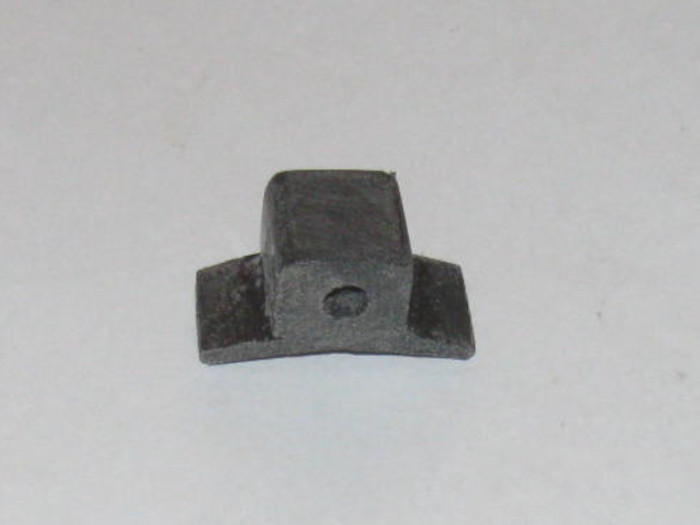
The short stub of brass tubing goes in to a hole driller in to the top
of the cylinder in the ballast tank section.
This is to help hold the plastic in place when the spring loaded valve
is pressing against the plastic body.
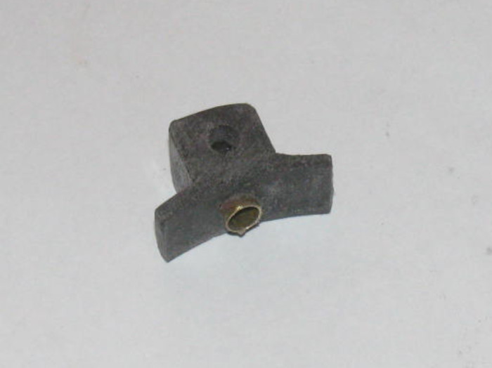
May 31th ===========================
I had a little time this morning before getting to other non sub stuff.
I measured center to center of the propeller shafts in the hull.
Then I put the cylinder with the end cap in it to get the center of
the shaft where it will meet the cap.
If I get this right, my propeller shaft dog bone will be straight.
(no angle except that where the propeller shaft goes through the hull)
I laid out the drive shaft gears on a piece of paper.
Then I took the third gear to see if it would fit above the 2 drive
gears.
But I also checked to see if the third gear would fit under the drive
gears.
If I can fit it under the drive gears, this will leave a little more
than half the end cap for control rod through bearings.
I cut 4 pieces of aluminum from my speed limit sign.
Cleaned the reflective coating off with the disk sander.
Sanded both sides.
Cleaned with thinner.
I glued the 4 pieces of aluminum in pairs.
Used tape to keep the pairs from sticking to each other.
Clamped them in the small vise.
I will shape them after they cure over nite.
I should have the pinon gear in the next couple of days.
Then I can start assembling the new gear box.
My new end cap fits very well.
I may not need to use the safety cables, now.
The original cap was water tight but not very tight in the cylinder.
(I worried that it might pop out)
Did a little more filling of holes in the end cap.
When done, I should have only 1 hole for the main motor shaft.
Remember, I made this cap out of a reject 5.25" diameter cap that had
hole in it for control rods. (not in the right place)
Now I have 2.5" diameter cap.
June 1st ===========================
I made it out to the shop.
The weather in the desert has turned.
By 10 am my shop temperature says 95F.
I am going to have to start earlier.
Okay.
Pulled the 2 gear box side plates out of the vise.
Did a little trimming but the glue is still tacky so I will have to
wait another day before shaping.
Made a brass exhaust tube.
It goes from just past the back of the cylinder to the first flood
hole in the ballast tank.
I cut a notch 3/8" back from the end of the tube.
When I bend it I get a 90 degree turn.
Solded the joint and checked for air leaks.
Good to go.
I cut a notch in the cylinder location plastic pin in the bottom of
the hull.
Well, I tried to cut a notch in that pin.
One side broke off.
So I got scrap plastic pieces from the floor.
Making a new pin with the notch for the brass tube in it.
This will hold the 90 degree bend up in to the ballast tank.
The other end will be made after I get the gear box finished.
Measured the cylinder for length and OD & ID.
Order new cylinder from Mac-Masters.
Pickup on Thursday morning. (I had other things to do which are near
their building)
Mostly of what I can do are busy work parts.
They can wait.
I am done in the shop.
It's up another 5 degrees in the shop.
Oh, while measuring and fitting the air exhaust tube, I measured the
end cap to the propeller shafts.
Withe gear box output shafts now straight withe propeller shafts, I
can make the cylinder another 1" or so longer.
Moving the equipment on the tray and an addition 1" of cylinder, I have
gained about 1.75" inside the cylinder.
I maybe winning the equipment in the cylinder space race. (yea)
June 2nd ===========================
What did I get done today?
I shaped the plastic part that will be in the bottom of the hull to
locate the cylinder.
It sticks up and will go in to the back flood hole of the ballast tank.
It has a slot in it to accept the air outlet brass tube. (air from
the air pumps)
The location is about 1/4" forward of where it was originally.
It was right against the tank bulkhead and I wanted a little space
between the two.
I used 1 hour epoxy to glue the part in place.
The brass tube is sitting in the slot to keep the part centered and
the slot in the correct direction.
Checked on my 2 aluminum plates for the gear box.
A little cleanup and I was ready to drill the 2 output shaft holes.
I marked one of the plates and set it int the hull to make sure the
marks lined up with the 2 propeller shaft dog bone connectors.
A little adjustment and out to the tool shed to drill the 1/8" holes.
Drilled 2 holes in the marked plate.
Held the second plate against the first and drill 1 hole on the second
plate.
I put a 1/8" rod shaft in the 2 plates to hold the plates while drilling
second hole in second plate.
This is all I can do until I get the pinon gears.
-------------
I got e-mail confirmation that the cylinder is ready for pickup tomorrow.
June 4th ===========================
Yesterday's trip to the big city had me coming home with a new length
of cylinder tubing for the Gato.
Today at the post office, there was a small package which contained
2 pinon gears.
I took the gears out to the shop and placed on the work bench.
How ever I will not be working out there today.
11 am it was 102F out there.
Tools on the bench were hot to the touch.
The plan is to get up early (like 5am) to get some work done out there.
See how long I can go before the heat chases me out of the shop.
I did bring the gear box parts in to the house so I can do measuring
and marking later today.
June 5th ===========================
The new cylinder is cut to length.
Fitted in to hull so the location pin is in the correct ballast flood
hole.
Flood holes drilled and cleaned up.
Remove ballast tank frames from original cylinder.
Drilled rear end cap for the motor shaft bushing and installed the bushing.
(I can mount the motor on the back of the end cap)
The rest mounts to the gear box.
I was laying out the location for the other 3 gears when I discovered
the new pinon gears are not the correct tooth pitch. (too small)
The original 3 gears are the same but the packaging and web site gave
no pitch.
I did a chat with Chris at the company and learned the the gears I
got are drive gears and they have no pinons that will work with them.
So I am on the search for new gears, or a pinon with teeth that will
engage.
I have a backup plan.
I have 4 of these drive gears and can use them to make this work.
The reason I wanted to go with the pinon was to get a 2 to 1 gear ratio
so the motor could run faster and the propellers would run slower.
The motor tends to cog a very low speeds.
But not having run the boat, I do not know what the slow speed will
be on the motor to get the cruise speed.
----------------------------
Can anyone point me towards a supplier of small nylon gear?
I braved the heat and went back out to the shop.
I wanted to get the cylinder in place and the location pin in the correct
spot.
Turned out the pin I made a day or so ago was too short and off center.
So I made a piece of plastic to glue on top of the existing pin and
go up in to the ballast tank by 1/8".
Got it made.
Put a slot in it for the air outlet brass tube.
Put the cylinder in and looking through it I centered the flood hole
on the hull over the pin.
I could see where to put the added piece.
Removed the cylinder.
Applied bonding cement to both the pin and the part.
Placed the part on the pin and held it for about a minute.
Carefully slipped the cylinder in to see if I got the part located
right.
In the right place. I just needed to twist it about 1/16" to square
it up to the hull center line.
While making the new cylinder, I found an issue I did not see with the
old cylinder even though the issue was there.
The front of the cylinder was not sitting in the hull saddle.
It was resting on top of one of the ballast blocks.
This made the front of the cylinder high by 1/4" actually.
This put part of the cylinder above the waterline. (not good for trimming)
This ballast block is not glued in yet.
It was one of 2 blocks I left loose so I could move them during trimming.
What to do?
That was easy.
Take the lead block out to the steel work bench out side.
Using a 24 oz ball peen hammer, pound the block thinner.
Measured the hull/saddle height so I would know how much pound I needed
to do.
Not much with 24 oz hammer.
Got it thinned out giving it a little gap now.
Took the ballast block over to the big vise.
I have short pieces of steel pipe I use to shape ballast blocks.
Pick one that has a curve that in close to the hull curve.
Put the block across the vise jaws and place the pipe on top of the
block.
A couple of good wacks and the block now has a nice curve to it.
Took it in to the shop for a test fit.
Needs another wack wit the hammer and pipe.
Back in the shop.
Place the block down in the hull and carefully place the cylinder in
the hull.
I can see the gap between the cylinder and block.
I pushed down on the cylinder at the saddle frames.
No More rocking.
Now I have to get back to try finding gears or make the decision to
use what I have and move on.
2 to 1 would be nice but I know 1 to 1 will work.
I even check to make sure it would fit after moving the propeller output
shafts on the gear box.
In the original gear box the extra gear was above the output shafts.
Now they will be under the output shafts.
The main motor is lower in the hull now by about 3/8". (maybe more)
I going out to the shop to close it up.
I will get a photo of the ballast block in place.
The block on the left is the one I pounded thinner to fit.
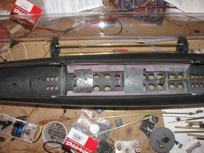
Here the cylinder is in place to check for clearance.
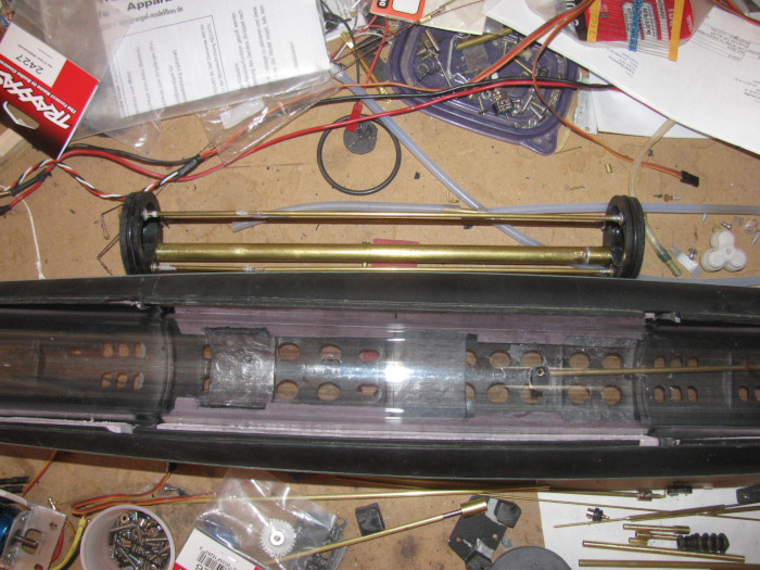
June 6th ===========================
I spent a lot of time researching gears.
What I found is not good.
The size is not something stocked.
What I found were $18 each and up to over $90, plus shipping.
There are custom makers but they do not give pricing.
So I went to the shop and started on plan B.
Using the 4 gears I have.
Easy enough to make them work.
The problem is, using these 4 gears covers almost all the end cap.
There would be no way to get 3 control rods and 2 water tubes in the
end cap.
When I placed the gears so I would have room for the control rods and
water tubing, 2 gears stuck out past the esge of the end cap so far that
they would hit the hull.
Okay, now I know what I am up against.
I reassembled part of the original gear box.
The issue with that gear box was the angle of the dog bone shafts.
With the cylinder and the end cap in place, I held the gear box against
the end cap and lined up the dog bones at both ends.
In the original position the output shafts where very low in the hull.
This was with the motor in the center of the end cap.
The new gear box was to get the motor down lower by 3/8" to 1/2". (with
out a small pinon, this will not work)
Anyway, I moved the gear box on the end cap until the 2 dog bone shafts
where parallel to the waterline. (only reference I had)
This change the dog bone angle to where it was much less of an angle
than original.
I marked the end cap with a pencil across the top of the gear box frame.
Measured the difference from original to new location of gears.
I was surpirses to see abut 3/8".
Tow things made this happen.
I moved the gear box up and remember yesterday I fixed the cylinder
to sit in the saddle frame correctly.
This brought the rear end cap up about 1/4".
I drilled the motor shaft through bushing hole in the end cap.
Originally I was going to cut the cup seal recess this morning after
layout.
The bushing was cut and is now glued in the end cap with the gear box
sitting in place with weights and the shaft going through to keep everything
straight.
I moved on to modifying the gear sizing bushings.
The hole in the center of all the gears is too big.
With a brass tubing I shimmed the hole down to the 1/8" shaft size
needed.
I needed to drill a hole in the bushings so the grub screw could go
through to the shaft pieces.
Did than and cleaned them up and fitted them.
Now the grub screws easily go through to the shaft.
The original gear box never looked right but the gears are in the correct
location
With calipers in hand, I measured the gear box frame.
I have shaped it by hand and eye.
Turns out one side is 1/16" wider than the other.
I will fix that after I get the gear box assemble again.
Little bit of belt sander ought to do it.
This will also lighten the gear box helping with trimming.
After so much time looking for gears, I think I will stay out of the
shop now.
The glue on the gear box needs to cure anyway.
I made the cylinder 1" longer than original.
I may have to cut about 1/2" off.
Still a net plus on the length.
June 7th ===========================
The shape of the gear box can be modified.
This will make more room for the 3 control rods and 2 air intake tubes.
While assembling the gear box, I check each shaft for square to the
box and end cap.
The motor shaft is a little off through the end cap so I will be correcting
that.
Easy enough to do.
Find a brass 1/8" rod to put through the bushing and then heat the
rod with the soldering iron.
This will soften the end cap PVC.
Once hot, I can twist the rod and change the angle of the bushing through
the end cap.
I have a fixture that will hold the rod while down pressure on the
end cap will push the cap down on the face of the fixture which is square
in all directions.
The gear box has been reassembled and glued.
It is in the vise until cured.
The glue holds it together but there are 2 stainless screws that go
through the gear box to the end cap which hold the gear box frame together
as well.
Cut a piece of the aluminum sign that will cover the end cap.
I have decided to go back to using o-rings instead of the rubber boots.
The rubber boots where strong enough in trying to go back to there natural
cast shape they were putting pressure on the servos.
These little servos would fail after some time because of the rubber
boots.
So it's back to the tried and true o-rings in the end cap with a plate
over them to squeeze slightly and hold them in place.
I have 10 years experiences with o-rings under flat plate in end caps.
Not one ever leaked or failed.
Besides, I think the o-rings and plate are actually lighter than the
rubber boots.
Something has come up and I will be out of the shop.
I did glue all the parts I could think of so they can cure before I
get back to the shop.
Found some small magnets I use in the Skipjack on the sail planes.
I think I will try them on the bow planes.
If they work out, I will try them on the 3 control rods at the back.
---------------
The fit for the crooked bushing through the end cap.
Before heating the bushing, I tried using a drill bit the size of the
tube outside diameter.
Placed the end cap over two metal blocks and let the bushing sit over
the gap between the blocks.
Using the drill bit back end, I put it the hole in the end cap where
the bushing is.
The bushing only goes half way through because I will be cutting a
recess for the cup seal.
A light tap of the hammer on the end of the drill bit, the bushing
moved.
Another tap and the busing moves again.
Third tap the bushing is clear of the end cap.
Place a [piece of stainless motor shaft in the vise using the V cut
to hold it square.
I check with my little square.
It looks good.
Cleaned the bushing off with the grinding wheel to get to clean brass
for the glue.
Applied glue and reset bushing in to end cap.
Flush on the inside.
Wondering why the hole was crooked.
I went out to the tool shed and looked at the drill press.
Found the problem.
Total operator error.
I drilled the hole alright but I did not check the drill press table
clamp tight.
The table is not square if the clamp is not tight.
So I think from now on I will tighten the clamp before leaving the
shop or swing the table away from center making it necessary to move the
table which would make me tighten it before use.
Looked for magnets in my parts bin.
Only have enough for 1 and a half control rods.
I may go to town tomorrow and get more.
Moving along every day. Progress!
June 8th ===========================
More measuring and test fitting.
The bushing could be moved using heat but when measuring again, I found
a piece of scrape masking tape in the bottom of the hull.
Yep, it was holding the front of the cylinder up so my previous measuring
was wrong.
So I started measuring, over.
The main shaft bushing needed to be moved up 3/16".
So heating the bushing will not do.
Put the cylinder with end cap in the hull making sure it is sitting
down on the saddles.
Hand held the gear box against the end cap.
Moved the gear box around until the dog bone connectors where straight
inline with each other.
I used a sharp metal scribe to mark the to location of the gear box.
I have been using a pencil but that has turned out to make a line that
is too thick and placement is not correct.
Took the cylinder out of the hull and removed the end cap.
Placed the gear box on the scribed line.
Measured to get the 2 out put shafts centered on the cap.
This will make the motor shaft off center by 1/16" or less.
Drilled the end cap for the bushing.
With a shaft through the bushing and gear box bushings, I located the
2 mounting holes.
These holes will have bolts that go through the gear box, seal plate
in to the end cap.
Marking these holes took some time as everything moves.
Finally I got some small pilot holes drilled.
Looking through the gear box I could see the pilot holes and knew which
way to make the hole so it would be centered.
Did this for both bolts.
Using a small drill with a short piece of brass tube over it, I drilled
the small holes in the end cap which will be threaded by the bolts.
The brass tube over the drill bit holds the bit center of the hole
through the gear box.
Even it it moves off center a little the tube keeps the hole centered
enough for the bolt.
I got the gear box, seal plate mounted on the end cap.
Not tight, I could move the gear box and or the seal plate to make
sure the 3 shafts move freely.
Slowly tightened up the 2 bolts and checked the shafts turning until
the bolts where tight.
Checked the bushing in to the end cap over the drive shaft.
It took several tries but I finally got the gear box tight and the
shafts turn freely with the bushing in.
Remove the bushing and apply the glue. (Gorilla glue expands and will
fill the gap in the end cap)
The shaft through the gear box and end cap will hold the bushing in
place while the glue cures.
Having gone back to the original gear box, the original electronics
tray should fit right in with maybe a little modification to the mounting
hole locations. (I shorten the tray by 1/2" or so)
Tomorrow, on to the electronics tray assembly.
June 9th ===========================
This morning, I finished installing the last bushing in the end cap
and gear box.
Lined every thing up and applied the glue to the bushings.
Make sure every thing turned and set it on the bench and weighted it
down so it does not move.
While messing with the end cap/gear box, I was looking at the ballast
tank frame.
I set the electronic tray sections together on the bench to measure
over all length.
It has changed because I cut a little off here and there to make the
tray shorter.
I also left the cylinder longer so I could cut it after the electronics
tray was compele.
The electronics tray is now about 1.3" shorter.
I had lengthened the ballast frame about 75" longer a while back.
My quick water testing last week says it might be okay but I could
lengthen the frame again while it is out of the cylinder.
So after messing withe end cap/gear box, I did just that.
I unsoldered the frame spreaders and lengthen them 7/8".
Extended the wire through tube as well.
The boat is an air pump boat so the ballast tank will be completely
empty or completely full.
No baffles used.
But if I try to do decks awash, I will have to have the boat at a steady
speed to keep the water in the ballast tank still.
Worst case, I have to remove the ballast frame later and add baffles.
No a big job at all.
June 11th ===========================
Yesterday at the VA seeing doctors on followup surgery stuff.
Everything is good.
Back this morning to VA for some paper work corrections.
This also went well.
No work yesterday on Gato.
Today, I worked on mounting stuff.
First I made sure the motor shaft through the gear box was straight
and turned freely.
Next I measured for the motor electronics tray end cap bracket.
Drilled 2 holes in end cap. (1/4" deep)
Installed this bracket.
Put the electronics tray that the motor is actually mounted on on to
the end cap bracket.
2 bolts and checked with square to get straight.
Tightened bolts and made sure motor shaft turns freely.
In one try.
Next I plan to install the 2 servos to this electronics tray.
I need them there to measure for new holes in the tray that will bolt
to the air pump part of the tray.
I shortened that tray by almost 1/2" so new hole locations is needed.
Tomorrow, I think I can get a few hours in the shop.
Undisturbed hours.
June 12th ===========================
I have been assembling the rear electronics tray.
It is in two parts.
The rear tray is the motor and 2 servos for rudder and rear planes.
I shortened that tray about almost 12".
All the parts fit just fine.
The forward tray has the 2 air pumps and a an actuating servo.
It also has the speed controller, and pitch controller.
The motor section was test fitted to make sure the motor will slide
in and not touch the cylinder wall.
Then the air pump section was slid in to check clearances.
All good.
Now I have to figure out how to connect the two trays together so they
slid in and out together.
The new motor location has changed how the 2 trays meet.
This means I need to figure out a new connection bracket.
The original plastic parts will not work.
I know this because I have already broke them off while trying to connect
the 2 trays.
I am thinking I might try making an aluminum L bracket for the motor
section because the motor section is an aluminum tray.
Then make a solid block of plastic I can bond on to the air pump tray.
Then I can use 2 small screws to mate the 2 trays together.
I spend some time this morning going from hardware store to hardware
store.
Auto parts store to auto parts store looking for wire cut to length.
Most would sell me a package of wire but it was 30' and $9 each.
I need 30" of 2 colors.
I have an old trailer out back, I should crawl under and see if I can
cut some wire off.
The trailer has been sitting for about 20 years.
Maybe more.
The wire may be too brittle.
I might have to use speaker wire and double it up.
=============================
I am finished for today.
Getting hot in the shop.
I was mounting the motor to the end cap.
Then trying to align the air pump tray to the motor tray so I could
build some sort of bracket to hold them together.
I have a short piece of cylinder for testing fit. (about 10" long)
I can see through to line things up and then remove them to make the
bracket.
I made 4 brackets in all.
Each one fit fine in the test cylinder but would bind the motor shaft
in the boat cylinder.
This was becoming a problem.
Then on test 4 the bracket fit fine in the test cylinder and it fit
fine in the boat cylinder.
That is until I put the boat cylinder in the hull.
WHAT?
It did not fit. ? ? ?
Looking down through the cylinder I could see the problem.
The cylinder pin in the hull was lining up with the ballast floor hole.
Took the cylinder out removed the motor tray and turned the cylinder
around.
Put the motor back in and crap?
The motor binds up again.
Something is not lining up and is causing the motor bracket to twist
and bind.
Took the motor tray out.
I stood the cylinder on end on the work bench so I could look at the
motor tray.
Reaching for a file, I see the problem. Big as Lift!
The boat cylinder is not standing straight up.
I turned it over and then the cylinder stood straight up.
Okay. This is where I think of all kinds of names to call myself.
I had made the assumption the factory cut end was square.
Using 2 small metal square, I checked both ends of the boat cylinder.
The end I cut was square.
The end the factory cut was almost 1/8" off square.
Out to the tool shed. (where the band saw lives)
I set the cylinder in the band saw vise and made sure it was sitting
flat on the table.
I set the cylinder to cut 5/16" off the long side I had marked on the
work bench.
I started the saw and I let it down but I held the weight so it would
not cut by just dropping because of it's weight.
I slowly made the cut.
Out of the saw and checking with my square.
The end is not square.
Yes, I checked the other end to make sure I cut the correct end.
I caused this problem because I did not check both ends of the cylinder
for square.
It would have saved me about 2 hours of making small brackets when
the first one will work.
I got the two brackets that hold the motor tray to the end cap installed.
The motor turns freely by hand.
I dropped a couple of bolts and one of the nuts on the floor.
I found the bolts but I could not find the nut.
I am using small bolts for this.
The bolt is 1/4" long and the nut is not 1/4" across. It is smaller.
So after I got the tray problem fixed, I moves a few things and swept
the floor.
Under the bench and around where my milk crate chair sits.
As I made the pile of dirt and plastic and brass filings, I see the
nut.
All is good with the world today.
More tomorrow.
June 13th ===========================
Today, I worked on getting the through tube bushing for the control
rods through the end cap.
I know it shouldn't take very long.
But it does because I put a recess in the end cap for each o-ring.
Rudder, rear planes and ballast vent valve.
The brass tube bushing does not go all the way through the end cap.
They stop short about 1/8" from going all the way through.
I use the bushing to guide my recess cutter.
The cutter is mounted on a 1/8" brass rod.
Both shaft seal cutter and o-ring cutter are on the same shaft.

How I made the cutter. ( along time ago)
[url]http://www.cliffhangershideout.com/cutter/cutter-seals.html[/url]
I also drill the 2 holes for the air inlet/outlets.
Cut the brass tube bushings and cleaned them up so the control rods
would slide through on their own weight. (no effort)
Before gluing them in the end cap, I make the tube for the depth to
push them in to the end cap.
Between the make and the end of the cap end of the tube, I grind notches
around the tubes for the glue to get in to.
The glue will expand during cure and this gives the glue something
to hold on to.
At 11:20am, the temp in the shop has past 100 F.
I am getting old and I no longer feel the need to try and push my way
through working on any thing.
Except maybe lunch.
So closed up the shop with the end cap in the vise to hold it straight
while the glue cures.
June 14th ======================
I have not gotten to making the o-ring cutter yet.
Instead I drilled the pressure plate that will hold the o-rings and
cup seal in place.
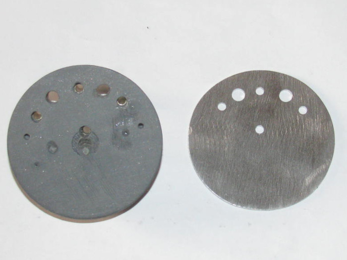
Test fitting all the control rods, air inlet/outlet tubes and main motor
shaft through the end cap and the pressure plate.
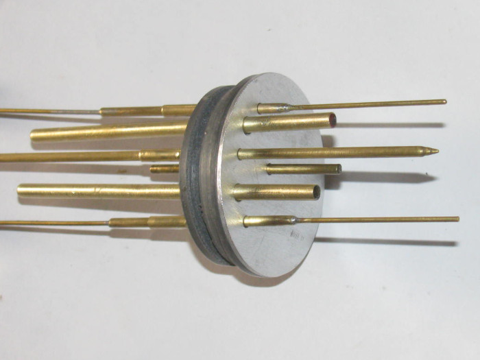
The pressure plate will be held on and down with the gear box mounting
bolts.
End cap, pressure plate and gear box assembled. ( no seals yet)
Rudder, rear planes control rods and ballast tank vent control rod
in place.
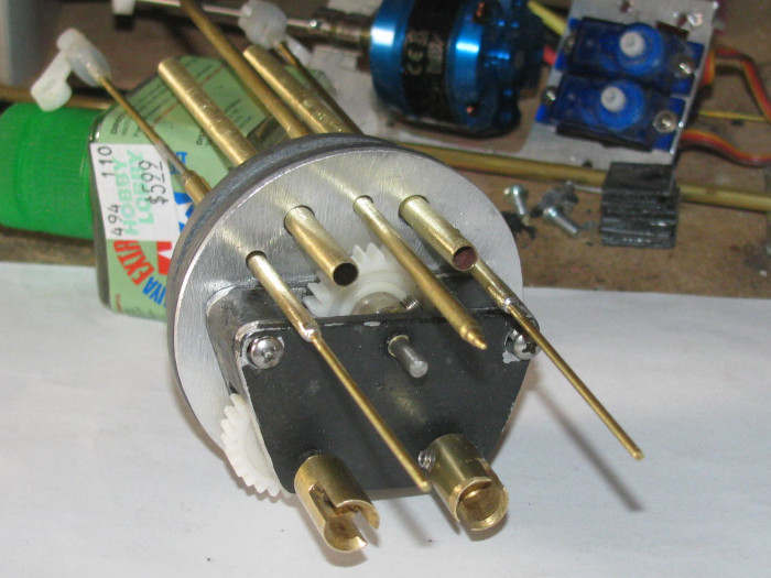
Now I will make the o-ring recess cutter.
June 15th ======================
The cutter was made.
Seals sitting on end cap.
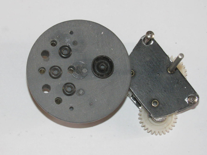
The motor shaft seal recess is cut.
The 3 control rod seal recesses curt.
Cutter still in last cut.
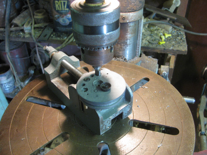
Checking alignment.
All control rods, motor shaft and air inlet/outlets pushed through
seals.
Air tubes get glued in later.
Test aluminum cover plate.
Looks like it will do it's job with 2 bolts holding the gear box and
the cover plate on.
June 16th ===========================
In the shop.
It's getting hot very early today.
I am gluing plastic parts together and the cement is drying before I
can mate the pieces.
I am having to put lots of cement on so it is still wet when I put
the pieces together
Still drying before I can get them mated straight.
Went with a bigger brush which seems to put enough cement on to stay
wet for 10 seconds or so.
I am using 2 pieces of 1/4" wide by 1/16" thick by 5" long.
I am making a plastic ring that fits inside the 2.5" cylinder tube.
Using a short piece of tube I am putting the 2 cemented pieces together
and quickly putting them in the cylinder to make a ring.
The ring will be mounted to the air pump section of the electronics
tray.
The tray keeps tilting as I hook the rubber air hose to the pumps.
The ring will go on the tray and hold the tray down and level in the
cylinder. (I hope)
Until I can keep the 2 trays level when joined together, I can not move
on.
Got the plastic pieces together and in the cylinder section.
Clamped with spring paper clips.
Okay, now that that is out of the way, I measured the air inlet and
outlet brass tubes.
I need the length of brass tube in the cylinder to be just so so the
rubber air hose will connect the pumps manifold to the through cap tubes.
Measured and marked.
Applied glue and push the tubes through the end cap.
Cap held in small vise.
tubes are taped to hold the angle straight and the other end is weighted
to hold tubes correctly.
Checking thermometers, it's 112 F on my front porch and 106 F in the
shop.
I think I am done.
I have cooler in house and just a big fan in the shop.
House wins.
I think I will order some cylinder magnets ans see what I can do in
the way of making magnetic control rod ends.
Seems simple enough.
I will make a plastic jig to hold magnets and allow pouring epoxy in
to make the cover and control rod end.
June 18th ===========================
Yesterday was real stuff to do.
This morning I was in the shop by 8 am.
Already very warm.
I started with the forward electronics tray. (air pumps and servos and
such.
When I put the tray in the cylinder, it would sit high at the back
end.
This caused misalignment wit the motor tray.
The motor tray is mounted on the read end cap.
The misalignment caused the rear tray to bind and not sit tight against
the end cap.
The top was about 1/4" from touching the cylinder.
Using my short cylinder piece, I put both trays in from opposite ends.
I could watch the 2 trays come together.
I made a plastic frame on Wednesday.
Basically a circle that would hold the tray down level at the back.
I worked on it until it fit and the tray was now level.
Sliding the motor tray in I can see the gap between the 2 trays.
l can make 2 plastic blocks to fill this gap and keep both trays level.
(gap is not quite 1/4" on each side)
Might make an aluminum frame piece for the offset.
Now The problems start.
I tightened the motor mounts.
There are 2.
1 mounts to the end cap and is an L shape.
The other is the flat long section with the motor and 2 servos.
The motor turns freely on the tray mount.
When I put the tray on to the end cap bracket, the motor turns freely.
That is until I start tightening bolts.
I put it on and checked it.]
I took it off and made small bend adjustments.
Almost 2 hours of this.
Finally I came to the conclusion that the connector between the motor
and shaft extension is not completely centered.
When I turn the motor off the end cap, It looks straight as it turns.
Then I finally put the tray in a small vise.
Now I can measure the shaft to the bench top.
Well you wouldn't think it but the shaft is off center by 1/64" or less.
(my ruler does go down any more than that. Should have use a micrometer)
I seems that my through end cap bushing is very close to the size of
the shaft and does not allow the shaft to move that 1/64".
Okay, what I did is I tightened the L bracket to the motor tray making
sure the motor turned freely.
As I tightened the bracket to the end cap, there is a point where the
bracket goes tight and flattens out on the end cap.
This is where the motor gets harder to turn. (not good)
I Moved the bracket here and there.
No luck getting the binding out.
If I untighten the bolt just a little, (less than 1/8 turn) the motor
frees up and turn nicely.
Okay. With the bold loosen, I can not move the bracket but I can see
it rocking back and forth as I turn the motor.
Solution.
Remove bracket so I can get under it.
I put a small bit of silicone glue on each end and in the middle. (talking
about 1/8" square blobs)
Now I reinstall the bracket testing the turn of the motor.
When the motor binds up, I backed the bolt out 1/8 turn.
Motor freed up.
I will let this cure and I should end up with a rubber gasket between
the end cap and bracket.
This will allow the bracket to move slightly.
When I make the connector brackets from the motor tray to the air pump
tray, I will use small rubber square on the bolts.
I might even make the space blocks out of rubber.
This will let the motor tray move and the pump tray will not put pressure
on the motor tray.
I will over size the bolt holed so the air pump tray will more or less
float up and down but not back and forth.
I just need the 2 trays to slide together in and out of the cylinder.
The 2 air hoses may do the trick.
They fill the end cap tube to air pump tray gap which is all of 1/2".
The weather here has turned ugly.
Last night I had lightning without thunder.
There were 1 minutes burst of big rain drops for a minute or two at
a time. (about 15 minutes apart)
Nothing is wet but the dust on my car is a mess.
And now that the heat is up, 9:45 am it was 104 F in the shop with no
wind at all.
Time to call it quits because think has come and gone for today.
June 20th ======================
Not much y
Today I was still working to get the motor bracket straight so the
motor runs free.
Well, I have been putting pressure on it here and there.
Finally I broke it back were the servos mount to the bracket.
No way to fix it so I have to make another one.
Out tot he tool shed and cut a piece of aluminum sheet.
Measure out where the opening for the motor and servos go.
There is also an opening for the wheel collar grub screw that hits.
Got the plate cut out of the big sheet.
Using a 1/4" mill bit, I straightened the free hand cutting edges.
Well almost.
I was about 3/8" from finish when the bit grabbed and moved the plate
binding the bit until it broke.
The bit was my dad from about 1946.
So now I have to find a new one.
Moved on to using the Dremel grinding wheel to cut in to the plate so
I can knock out the openings.
As I started the first cut, BANG! the wheel disintegrated.
Looked to put another wheel on and there it is.
An empty grinding wheel box. (that's just not right)
I finish measuring for the opening and bolt holes and set the aluminum
piece down on the bench.
Done for the day before I get hurt.
Tomorrow will be go to town and find grinding wheels and a mill bit.
Only good thing about all this is I can make the opening for the motor
small front to back by 1/4". (more room in the cylinder)
Oh. . . I will not be mounting the front rear tray to the back rear
tray.
While fitting the motor tray in an out trying to align it, I noticed
the air pump tray will bounce up and down with the motor rotation because
of the1/64"-minus offset.
But while turning the cylinder over and over checking clearances, I
see that I can make 2 aluminum strips to go from the tray under and around
the motor to the air pump tray.
The motor will not effect the air pump tray and the 2 trays will be
solid to the end cap. (they can move independent of each other)
So I made 2 strips to mess with and see if this works out.
Weather says tomorrow and next 4 days the high will be in the 90s so
I should be able to get more time in the shop.
Drilled holes in corners of the openings.
June 21th ======================
My job today is to find tools to replace the ones I use and have broken
First I did some searching on net.
Found the mill bit.
I should have know so looking would have been easier, it was not a
mill bit.
It was an air grinder burr bit.
Any way. I found a set of 5 that has the size I use and 1 smaller and
3 bigger.
Price as okay compared to others I looked at.
Not expensive but not cheap either.
Ordered it and it will get here in about 2 weeks.
Now to find Dremel grinding wheels.
I only have about 4 places with in 30 miles that might carry them.
Check Lowes and found that 1 of their 2 stores has 3 packages.
The other, none.
For back up there is a little tool store that has some but at a high
price.
So, I think I need to get in the car and go.
I can not continue on my Gato work with out the grinding wheels.
The mill bit I can do with out using small files.
Just much slower.
I hope is to find the grinding wheels and get back in the shop tomorrow
morning.
Weather tomorrow says low 90s. That is great.Weather for Tuesday says
mid to low 80's.
I might have to get my coat out again.
Beings I have to go to big town (34 miles) I will get other stuff not
related to subs while there.
Finally home from today's trip to town.
I have in hand small plastic tube sort of with 12 metal grinding disks
for my Dremel.
This means I can continue working on the electronics tray.
I found some 20 gauge wire to replace the bigger wires through the ballast
tank.
I will run test with the motor to check current draw.
The mill bit I want to replace is not a mill bit at all.
It is an air grinder deburring bit.
Got those on order and will be here in a week.
I continue working without it. (files)
Tomorrow I have no place to go and can start early in the shop.
I hope to get the tray finished and mounted on the end cap.
===================
Forgot to mention, I was at the post office and the magnets for the
control linkage are here.
They are strong little buggers.
3/16"x1/4" at N48 strength.
There are 50 of these little magnets.
I opened the package and messed with them.
I found I could put them all in line, one after the other and then
pick up the complete line of magnets from just hold there end magnets.
Not hanging down but holding then horizontal to the desk.
June 22nd ======================
Out in to the shop early.
I finally got the motor to turn freely.
I cut the tray removing the servos from the tray leaving only the motor
on the bracket mounted to the end cap.
The servos were heavy enough to apply down pressure on the end of the
tray binding the motor in the bushings.
Once the motor turned freely, I installed the gear box.
Gain the motor start binding.
Measuring and using a square, I found the gear box was lifting the
shaft up as it came through the end cap.
The end cap has a brass tube bushing. The gear box has 2 brass bushings.
(one on each side of the gear box frame)
The end cap and inside gear box bushings where so close they touched.
I knocked the inside gear box bushing out of the frame and no the shaft
uses the end cap bushing and the outside gear box bushing.
Motor now turns freely again. (there is plenty of support for the shaft.
On to the air pump tray.
I have to figure out how and then build a tray to add to the air pump
tray to hold the 2 servos.
Currently building up the plastic section under and behind the air
pumps.
Once built and cured, I can start making the frame to hold the 2 servos.
I have checked for clearance and it is there with room to spare.
Just a lot of small parts in plastic and aluminum to make and assemble
to get every thing to line up.
I gained another 1/4" in the compartment by cutting the servos from
the motor tray.
All these small parts make it a slow build.
I looked at the magnets I received and I have all the brass tubing sizes
to make connectors.
What I found to be short of was 1/8" wheel collars. I have plenty of
1/16" collars.
Order 1/8" collars and will be here next week.
Things are going slow but progress is being made.
-----------------------------
The plastic parts will not work where I want then.
So, I made aluminum parts.
The aluminum tray section that holds the 2 servos and connects to the
air pump section is now cut out and drilled for screws and bolts.
I need to make 2 strips about 3/16" wide and about 3.5" long.
I need to bend one end of each 90 degrees to mount to the end cap next
to the motor bracket.
Once I have those made and bolted to the end cap, I can slip the air
pump and motor trays in to my test cylinder to see how long the 2 strips
need to be to hold the air pump tray clean of the motor.
Knowing the length I can drill and bolt the strips to the air pump
tray.
This will keep every thing clear of the motor tray and motor.
If the aluminum strips do not do the job, I think I can use brass tubing
with flatten ends.
I am done for the day.
I forgot to take my morning meds and I just ran out of energy.
I will go fix this issue with lunch.
June 23rd ======================
I think I have finished making aluminum brackets.
I need 4 very small bolts which I will get today.
Now for some photos. (FINALLY)
Here is the servos bracket mounted to the air pump tray.
Side view.
Motor tray with the bracket extensions mounted to end cap.
The extensions do not touch the motor tray.
One on each side about 1/4" wide strips of aluminum.
Looking at bottom of tray.
Here both the air pump tray and the motor tray on end cap slid in to
my short test cylinder.
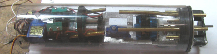
Side view.
4 small bolts, 2 on each side will hold the extensions to the servo
tray.
This will make all the trays in to one units so the servo control rods
can not push them apart.
I will need to shorten the air intake/outlet brass tubes.
I also will need to do a little bend of these tubes so they line up
again.
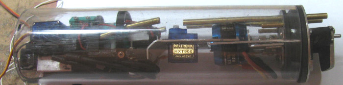
It all fits and is about 2" plus shorter.
-------------
Back with the 4 bolts.
Took the trays out to the tool shed.
Tool shed has the drill press.
Now to drill holes in the 2 tray parts.
Measured the motor frame with the air pump frame and marked where I
needed 4 holes.
I only drilled holes in the motor tray.
I will then drill 1 hole in the air pump tray with the motor tray clamped
to it.
Once I get 1 hole drilled, I will put a bolt through and tighten it
up when I get the 2 frames straight. (by testing in cylinder)
Drill another hole and put in another bolt
Continue until all four bolts are in.
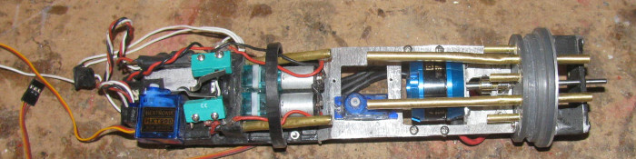
All the rear compartment trays and brackets are assembled.
Next will be installing 2 servos and running wires.
June 23rd ======================
Today, I have bent the air inlet/outlet brass tubes so they line up
for the rubber hose.
I did not have to cut the brass tubes.
There was enough room to slip the rubber hoses on.
This also gave me more clearance from the motor.
On to the 2 servos.
The holes I driller were off a little.
But to make them work I files the screw holes on the servo tabs a little
wider.
Worked out great.
Mounted the rudder and rear planes servo.
Time to test fit the control rods.
Fit like I measured it all.
I sort of used the old cap to guide me.
Small changes here and there.
Looks like I will need to bend the 1/16" rod at the servo ends about
1/16".
There is 1" 1/16" rod from the clevis to the 1/8" brass tube that goes
through the end cap and seal.
That will wait until I power up the systems to see how the control
rods move.
With the shortening of the trays, I needed to make the 1/16" control
rods that are on the servo end, shorter.
I measured what I needed which was 1" on both control rods.
Got out the soldering iron and small vise and removed the clevis ends
from the control rods.
Ended up cutting about 1.25" off each rod.
Soldered the ends back in to the larger tubes making sure I have 1"
between the clevis and the larger tube.
Next I test fit the long 1/8" brass tube that activates the 2 air pumps
and the ballast tank vent valve.
In the photo above, tube goes through the center end cap tube.
Between the 2 larger air tubes.
It goes back through a plastic guide just to the right of the green
switches.
The long tube goes between the 2 switch with wheel collars on the tube
to activate the switches.
The test fit shows it will work but the control tube is so close to
the motor housing I decided to move the bushing tube in the end cap.
I have a brass 1/8" rod with a ring of brass tube slipped over and
soldered just for removing through cap bushings.
Couple of taps with a small hammer while the end cap is supported with
crack the glue and the tube comes out with a little effort.
Cleaned the glue off the bushing tube and then I cleaned out the hole
through the end cap.
With a small file I enlarged the hole in the end cap .
I move it up and away from the motor.
Testing several times as I go.
Got to be careful not to file in to the o-ring groove.
Files until I got about 1/32" clearance from the motor.
Checked the material on the end cap to the tube.
Plenty.
Looks like about 1/8" or more from the bottom of the o-ring groove.
I put the control tubing through the end cap and through the guide by
the switches.
I put the short brass tube bushing on the control tube.
I silicone grease the control tube so if an glue gets on it, the tube
will slip out.
Put glue on the bushing tube and pushed it through the end cap to the
proper depth.
I put a small wedge of soft foam between the motor and the control rod.
Making sure the control rod does not settle down on to the motor housing.
Now to let the glue cure.
Once the bushing is cured in place, I will use a short control rod
piece and put it through the bushing.
Tape it on the inside of the end cap.
Set it up in the vise and file the o-ring recess.
Then I can fill the recess with glue and when cure recut the recess.
Now a thought.
I should test fit the o-ring seal before filling the recess.
I may not have taken enough material out of the end cap to make this
step necessary.
Yep, test fit o-ring first.
June 25th ======================
The control rod for the air pump switches and ballast tank vent has
been cleaned up and works great.
Plenty of clearance from the motor.
I installed the rudder, rear planes and air pump control rods.
Connected servo horns.
Charge the 2 boat batteries.
Now to connect the power and start connecting the servo plugs.
One by one I plugged in servos and tested.
As I go they are working as they are suppose to.
I have 1 bad servo on the bow plane retract.
Sounds like the gears have a lost tooth or two.
Not a problem, I have plenty of these little servos.
I will replace it.
Now the fun begins.
Powering up the main motor.
ECS beeps when turned on but it did that when powering up the servos.
Okay, operate the Tx control stick.
Motor stutters in both directions.
Tried this several times with the same effect.
Then the motor stopped all together.
Removed the motor from the electronics tray.
Dis assembled the motor.
A single spring "C" clip and then tap the shaft with wood block.
I have the motor a part on the bench.
Well I see the problem immediately .
The several months I have been rebuilding the electronics trays, I
have had to move the motor wires and all other wire so many times to work
around them, that the 2 wires to motor have separated or broken.
This is something I can not see me fixing.
Not a motor guy.
I am seeking help to repair and I have also sent a message to Engels
about replacements. (their web pages say OUT OF STOCK)
So the Gaot project is now stopped until I can find out what I can
do.
I might be able to reassemble the motor and reinstall it to do water
trimming.
Everything works except the main motor. (just not plug it in to power)
The Engel's motors are low RPM and high torque.
I looked for weeks for a similar motor for the rescue barge.
NO luck at all finding a match.
The Engels motors run so smooth without cogging at low speed.
If I can get another Engels motor, I may have to order several just
for shop stock here.
So today was a good day except for the motor issue.
June 27th ======================
Yesterday, I looked at the motor armature (where the wires connect)
with a 10X magnifying loop.
After a few minutes the conclusion is the motor is junk.
So I am looking for a new motor and Engel's does not have the correct
motor in stock.
Been a couple of months out of stock.
But they have a large motor. (500)
I did some research and learned what all this stuff about brushless
motors means.
Okay, the motor I wanted is a 300kv motor.
I have it in 2 subs and like it a lot.
When comparing the 500kv motor it was a first a problem.
The kv number multiplied by the battery voltage gives maximum rpm.
Out comes the spread sheet.
Reason for that is the Gato is 7.4v and the other 2 subs are 12v.
Turns out if I use the 500kv motor the rpm comes down to only a 100+
rpms difference.
The Tx I am using to runt he Gato is a Futaba with computer adjustable
channels.
If I adjust the Tx to 50% then the 500kv motor will run slower than
the 300kv motor in my other boats because of the battery voltage difference.
So the Gato is back on track.
I will order motor Friday because Engel's is closed for a week.
Now in the shop, I am measuring the cylinder and the electronics trays
to see where the ballast tank frames will go.
Starting at the back, I slid the tray and equipment in to the cylinder.
Marked the cylinder for the ballast tank frame.
With this mark I can fine where to put the vent valve body on top of
the cylinder.
3/4" in front of the frame. (used old cylinder to see where I put everything
on it.
Drilled the vent hole in the cylinder.
Place the vent valve body over the hole.
The vent body has a short piece of brass tubing sticking out that goes
in the vent hole in the cylinder.
Keeps the valve body from moving when the control rod and springs are
attached.
Drill the 2 bolt holes to hold the valve body on.
Moved on to make the 3 plastic control rod guides that will mount on
the top of the cylinder.
Currently in the vise and will be shaped later.
Well it is hot in the shop but still tolerable.
So, I started cutting brass tubing pieces in various sizes. (diameters)
The little magnets showed up Friday.
I am going to slip the magnet in to the large brass tube and then size
it down to the control rod size.
I have 2 sets at different point of completion.
I am going to wait and see how these work l before doing the bow plane
connectors.
These little magnets feel like they might be too strong. (I might have
to go 1 size smaller in diameter 1/8")
Okay, now it is hot in the shop.
I give up.
June 28th ======================
Saturday, I got an e-mail saying the wheel collars I ordered last week
where delivered to the post office.
Went to town and picked them up.
Did a couple of other things while in town.
Out to the shop.
10 am and it is already hot.
No matter, I will see what I can get done.
Got the 3 plastic pieces out of the vise.
Set them aside with the other parts.
Not going to work on them in the heat.
So I will continue making the magnetic connectors.
Cut lots of brass tubing in various lengths.
On to assembling them.
Get 4 magnets out of the baggie.
I made the parts that hold the magnets the other day, so now I am slipping
tubes to go from 3/16" ID tube to 1/16" id tubing.
The part that holds the magnets is made of 2 brass tubes slipped together
to give me a shoulder to push the magnet against.
I have cut enough parts.
Put glue on magnets, one at a time and slip in to connector.
Next I put glue on the 2 tubes that slip in to the connector.
Did this to 2 magnets.
Put the unit in the vise.
Now I take magnet and place it on one of the magnets in the connector.
It will self align by flipping around to mate up.
Glue in connector and on tubes.
Slip together.
Do the 4th one.
I now have 2 magnetic connectors for the control rods.
I will let cure over night and then clean them up.
Okay, it's now 12:30pm and I am hot. (112 F in the shop)
The tools are hot to the touch.
Time to go inside the house.
Making the magnetic connectors was easy enough.
I think I will make connectors for the bow planes.
Not today.
June 29th ======================
Good news from Engel's.
The 300kv motors are in stock.
I ordered 3 this morning.
Out to the shop to work on magnetic connectors.
I made the 2 sets for the rudder and rear planes.
Forgot photos.
So I started making 2 sets for the bow planes.
I cut all the brass tubing pieces.
I tried to show them all but the magnets would not let me put them
all in the same photo.
The magnetic attract from 5" away.
So here are the parts for 1 magnetic connector.
Top part is the magnet.
Going down are tubes reducing in size to slip together.
At bottom of photo is a completed connector.
It will slip over the control rod end which is 1/16" brass rod.
A wheel collar will hold it in place.
There will be 4 with the wheel collar which go on the control rods
coming through the end cap.
The control rods going to the planes and bow stuff will be fixed on
the control rods.
There is 1 more brass tube. I do not have the one that slips over the
1/16" rod.
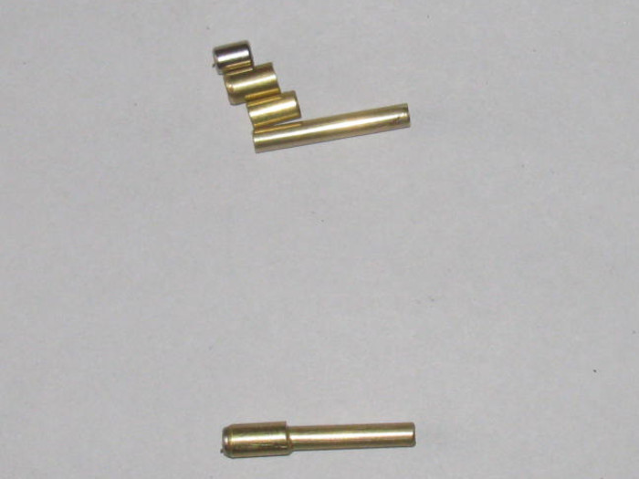
I will get these assembled today except for the smaller tube.
June 30th ======================
Today was a VA appointment.
Followup to eye surgery a year ago.
All good.
Got home about 10:45 am.
Decided to go out to the shop and see what I could get done in the
106F heat.
I assembled the 4 magnetic connectors for the bow planes.
Just a matter of applying glue and slipping together.
Making sure I have the magnet ends correct.
Okay.
I have 3 plastic parts that will guide the vent control rod that I
assembled the other day.
I shaped them and fitted the base to the cylinder diameter.
Got to wait for the glue to cure.
17 hours minimum.
Good time to stop and go inside the house where I have the cooler running.
Tomorrow I may not get any thing done.
Tomorrow I think I will run around town for brass tubing and other
parts like bolts to replace the grub screws in the wheel collars.
Something I do because the little Allen set screws tend to strip out
where the Allen wrench does not work, I replace those with stainless bolts
with Phillip's heads.
These work on wheel collars I use on control rods and do not need to
be balance for spinning.
With the Phillips head bolts, I can get them tighter and still loose
them when needed.
July 2nd ======================
Nothing was done yesterday.
I did get some parts while out and about.
So far this morning, I have finished cutting the brass tubing to make
16 reducers for the magnetic connectors.
Went from 3/16" id diameter of the magnets down to 1/16" id of the
control rods.
4 connector pairs have been assembled and the glue is curing.
Now I am off to do real life stuff. (sure does get in the way)
-----------------------------
Back for town and took the bolts out to the shop.
These bolts are for the wheel collars.
I even put a bolt in to a few of these as I need 4 now.
Took a wheel collar with the bolt and slipped it on to the magnetic
connector shaft.
Wait, did I screw the bolt in to far?
Nope!
Okay, what did I do wrong.
A quick inspection and it was easy to spot.
I had added 1 too many long brass tubes while reducing the size from
the 3/16" to the 1/16".
The wheel collar would not slip over the outside tube.
Second or third one in the reducing sequence.
Easy enough to fix.
The glue I am using takes 17 hours to cure.
So I took 2 pairs of pliers and twisted the tubes and they cam out.
I cleaned up the inside of the tube with a drill bit.
Cut the over sized tube down to be flush in the connector and leave
the correct tubes sticking out.
Cleaned up those tubes and applied glue and slipped together.
I did check the wheel collar fit before the gluing.
So by morning, the connectors should be ready to cleanup and fit to
the control rods sticking out ot eh end caps.
The I can measure in the control rods in the boat.
Rudder, rear planes, bow plane retract and bow plane pitch.
With the wheel collars I should end up with 3/8" of adjustment on each
connector.
Not so hot in the shop.
Only about 100 F.
Should not get hot until next Wednesday or Thursday.
Next Wednesday I plan to prepare my Akula II and my barge for Saturday's
gathering at the lake.
Just need to check the batteries.
July 3rd ======================
In the shop about noon.
Warm but not to bad.
I have to trim glue before it turns in to rock and I can not
cut with knife and have to use a grinder.
I finished 4 sets of magnetic connectors.
Rudder, rear planes, bow retracts and bow pitch.
As I assembled them I made sure the magnets where installed so they
were opposites.
Take the top pair. (rudder and rear planes)
They will not connect any way but like they are.
If I try to switch the top to bottom they will repel.
So as I put the cylinder in the hull, they should connect on their
own to the correct partner.
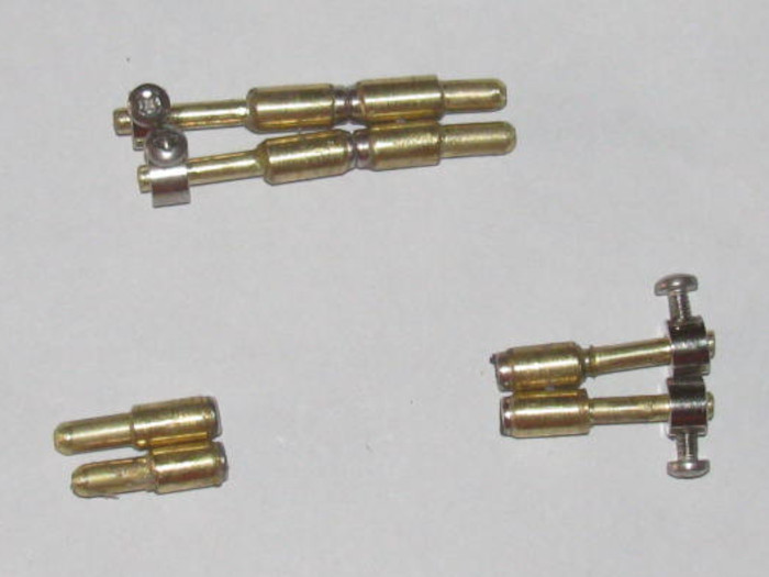
I put the rear end cap in the photo.
I have cut the control rods coming through the end cap to length.
The 1/16" control rod will slip in to the connector all the way to
the magnet base.
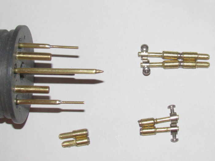
Here the adjustable connector is slipped on to the control rod.
The top one is all the way out to full length.
The bottom one is all the way in .
The amount of adjustment can be seem by how much control rod is showing
in at the top connector.
About 3/8" plus.
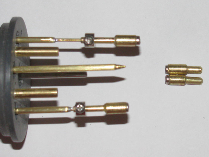
Put the non adjustable connector on to the end cap connectors.
The bottom one has a length of 1/16" brass rod in it.
You can also see the small bolts I use instead of the Allen screws.
These are so much easier to tighten and loosen that the Allen screws
that strip out too easily.
The bolt goes through the tubes on to the rod.
No soldering required. Just a drill.
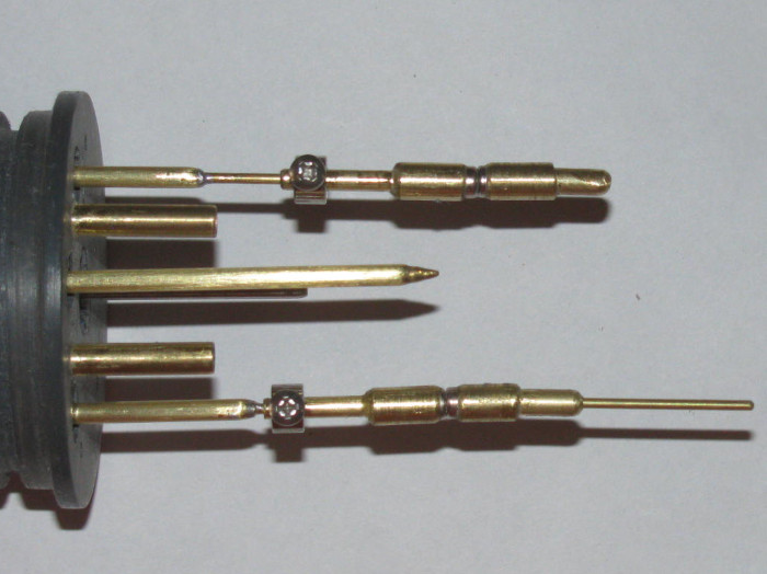
Once I get the cylinder completed, I can put it in the hull and then
cut the control rods in the boat to length.
July 4th ======================
I had about 20 minutes out in the shop before other stuff happens.
So I measured the 2 dog bone extensions.
[img]http://www.cliffhangershideout.com/Gato/gato-318.jpg[/img]
I need to shorten the dog bone by 7/8".
Grind off the heads of the brass pins.
With a piece of 1/16" brass rod, I tapped the pins out on one end leaving
he other end intact.
I need 2" end to end on the dog bone.
Mark the tube and cut with grinding cutoff wheel.
Well that did not go well.
I cut on the wrong side of the mark and my tube is too short.
I will have to make another tube.
Looked around t find I did not have a length of the tube the long enough.
I will have to pick some up later.
On to the second dog bone.
Using tape to mark the tube, I got a good cut with the correct finish
length.
I installed the dog bone end in the tube and drilled and pinned it
in place.
Test fit in the hull with the cylinder in place with end cap.
There is not quite 1/8" movement between the dog bone connectors.
The propeller turns easily.
I have a good dog bone.
I have an appointment in town tomorrow so I will go over and see if
I can find the more tubing after it.
Have a 1/2" sample to take with me.
July 6th ======================
I found brass tubing yesterday.
This morning, I got ready to make a new dog bone extension.
Of the 4 sizes of tubing I got, I was 1 size too small.
They did not have the next larger tube.
So in the shop I found 2 short pieces of the right tube and soldered
them together with a brass tube sleeve inside.
I could not bend them apart so I am going to use it.
Dog bone extension is complete and tested in the hull.
Next, I decided to mount the 3 plastic brackets for the ballast tank
vent valve control rod.
I measure and locate where the 3 brackets will go and I tape on the
cylinder the areas to be lightly sanded.
Apply CA to the bottom of the first 2 brackets and place them on the
cylinder making sure the valve seal is lined up centered and straight.
Put the second bracket so the control rod is at the mark on the end
of the cylinder to line up with the end cap control rod.
finish with the third bracket.
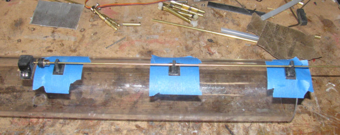
July 7th ======================
Got out to the shop early so I could get some thing done before doing
real life stuff.
With the front and rear electronics trays out of the cylinder and on
the bench, I connected the battery wires and powered up the system.
What I wanted to do was center up the rudder and rear planes servos.
Once centered I put the retaining screw in the servo arms.
Turned off the power and disconnected the battery wires.
I didn't want to mess with pulling the battery wires through the ballast
tank and stuffing everything in the cylinder.
With the rear electronics tray disconnected from the batteries, I carefully
slide the rear electronics tray in to the cylinder making sure not to move
the servos.
I put the 2 magnetic connectors on the control rods making sure they
were centered in the adjustment on the rod.
Put the cylinder in the hull watching to make sure the alignment bracket
hooked the flood hole. (keeps the cylinder from moving)
I connected the back part of the magnetic connectors on to the front
connectors.
I carefully lifted the rear planes control rod up to the magnetic connector
and set it in top of the connector.
From the side I looked and adjusted the rear planes to level.
Marked the control rod wire where it sat on the connector.
Took the rear connector half out and slipped the control rod in to
it.
Checked the mark I put on the rod.
I had to cut about 3/32" off the rod.
Slipped it on again and put in the hull and let it connect to the front
magnetic connector.
Holding the control rod with needle nose pliers, I adjusted the control
rod while connected until the rear planes where level.
Then I did the same with the rudder control rod.
Now I know I can adjust both with the connectors on the end cap centered,
I have adjustment on the magnetic connector on the end cap control rods.
I marked both control rods where the connectors sat.
Removed the connectors from the control rods and files a few marks
in to the control rods for the glue to catch.
Applied glue to the rear planes ans slid it on. the control rod.
With the glue the connector moved easily.
Connected the 2 magnets and adjusted the rear planes to level while
holding the control rod coming out of the end cap.
Did the same to the rudder and got rudder centered under the hull.
I will leave it all to cure and get to the real life stuff before it
get too hot.
Photo of connectors in place.
The wheel collars have bolts instead of Allen screws which makes tightening
so much easier.
No stripped Allen sockets or threads.
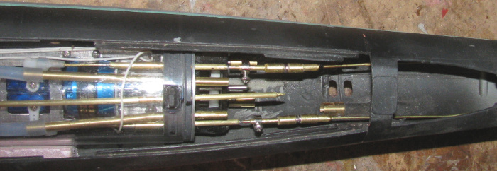
July 9th ======================
Went out to the shop to gather up tools for the lake tool box.
It is still cool but going to get hot.
Before moving the Gato so I could put the tool box on the bench, I thought
I might measure for the bow plane retracts and bow planes control rods
with magnetic connectors.
Shorten the control rods coming through the front end cap.
I have not decided if I will put o-ring seals instead of the rudder
boots.
The boots have been working so I think I will leave them for now.
Ground the tube with a notch so the set bolt will go through to the
control rod. (ones at the end cap)
Cleaned out the brass tubes so they slipped on to the control rod easily.
I made new control rods to the bow planes assembly.
They needed to be much shorter so 90 degree bends where required.
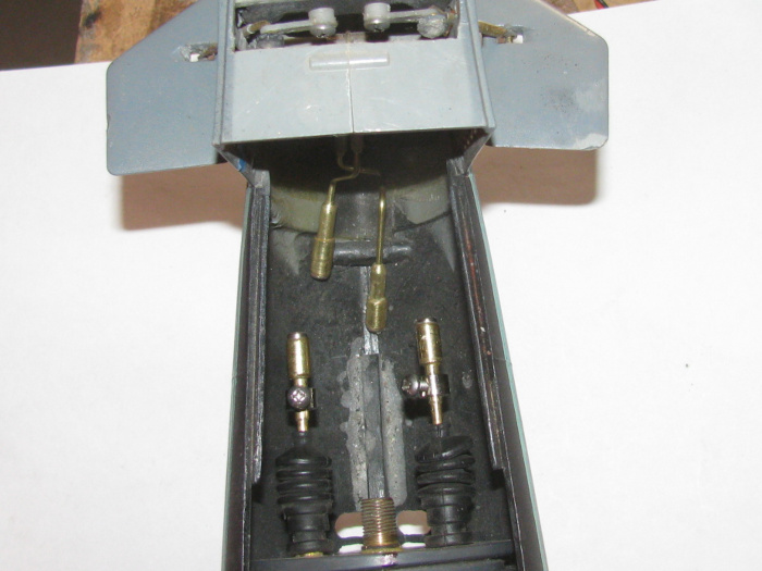
Testing connectors for travel.
Bow planes are in the up position.
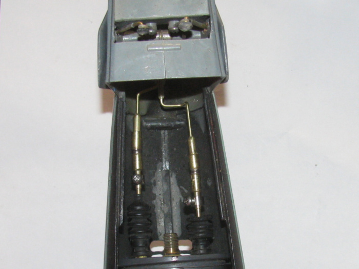
Bow plane extended.
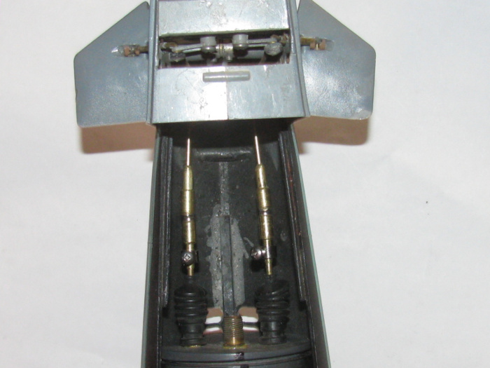
July 12th ======================
In the shop very early.
Temperature gets over 110F by 10am.
Got home Saturday from the lake gathering to be greeted by 119F on
my front porch.
Animals hibernate in the winter.
I hibernate in the summer.
Okay, in the shop.
I put the rear electronics tray in the cylinder.
I hooked up the front electronic tray through the cylinder.
This was easy because the ballast tank frames are not in the cylinder
yet.
Powered up the Tx and Rx.
Made sure the front servos where on the correct channel.
Put the cylinder in the hull and linked up the magnetic connectors
to the bow planes.
I needed the Bow plane retract in the stowed position (up)
I needed the bow planes level.
Put the Tx controls in those positions.
Then I slid the magnetic connectors on the bow side until I got the
bow planes up and marked the control rod with black marker.
Got the planes level and marked that control rod with black marker.
I removed the retract control rod and I made cut marks on the rod with
the wire cutters.
I did this until the rod was tight in the connector.
I put glue on the rod and pushed it in to the mark.
The cut marks also hold glue.
The glue will expand and hold on to the notches.
Did the same to the pitch control rod.
Set aside to cure.
The frames that my cylinder sits on where place for the first cylinder.
Now that there is 2" plus more inches at the rear of the cylinder,
when I push down on the end cap, the cylinder rocks in the 2 frames.
Easy fix.
Make a plastic block.
Shape it to the hull bottom and to the cylinder diameter.
Measure the end of the cylinder height from the bottom of the hull
when in the 2 original frames.
Test fit plastic block and trim until the end of the cylinder measures
the same as without the block.
Testing includes pushing down on the cylinder.
Glue it in place 1/2" from end of cylinder.
Cylinder is now solid in place.
With the hull block curing.
The control rods curing.
There is not much I can do at this point.
96 F is a good time to stop for the day.
July 13th ======================
I was going to take video of rudder and rear planes.
Bow retract and pitch control.
As I installed the bow plane magnetic connectors I could see I had a
problem with the retract connector.
It was too long by about 1/4".
I put it in the boat and sure enough I could not adjust in the bow
planes retracted position.
Bent the control rod but it was not enough.
Removed the retract connector from the boat and went on to disasembling
the rod from the connector.
Hoping not to damage the connector tubes.
Success.
Using a 1/16" drill bit, I cleaned out the connector for the control
rod.
I cut just short of 1/4" and cleaned up the end of the control rod
with the grinding wheel.
Test fit and measured.
Applied glue and pushed the control rod in to the connector making
sure to get to the black mark.
This time I clamped the connector and control rod to a steel straight
bar.
What I think happened is as the glue cures it expands and it pushed
the control rod out of the connector.
The other control rods may have done the same but there is enough adjustment
that I did not notice if the rod was pushed out a little.
======================
Just remembered I need to go out and get the battery out of the Tx.
I have ran test so much the low battery beep started up on me.
July 14th ======================
This is with retract link shortened, 1/4".
Planes up.
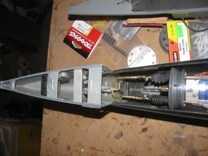
Planes down.
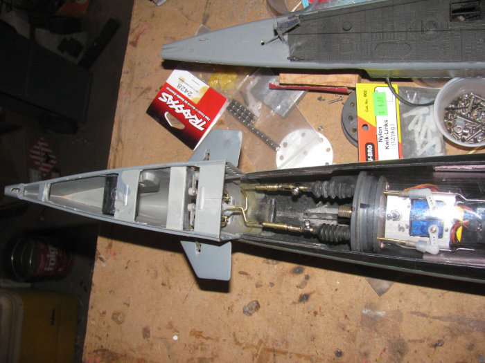
I did a video of the planes operating.
However I do not know how to rotate the image so it is not on it's
side.
===========
Back from town.
I got a message last night that my Engel's order was at the post office
and ready for pick up.
I have three 300kv motors and 2 speed controller.
It's like my birthday or Christmas!
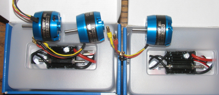
It will take about 10 minutes to remove the bad motor and replace it
with a new motor.
Sorry to say, I may not get to it until Friday.
Or if I get up early tomorrow before leaving for the day.
Never know.
Note: the power wires are smaller in sized.
I always thought the originals where over sized for the job.
===continuing=================
Well, we know what happened.
Sitting here on the computer with 3 new motors sitting there.
JUST sitting there.
I could not resist.
Took 1 motor and headed out to the shop.
It took 7 minutes to remove the old motor and install the new motor.
I pulled all the plugs out of the Rx.
Ten I plugged in the motor speed controller.
Plugged in the power from the speed controller to the Rx.
Plugs the 2 battery wires in to the speed controller.
This should give me the speed controller and motor.
Yep, it came alive.
Now the fun starts.
I can only get forward from the Tx.
Something changed (speed control programing)during all this messing
with the motor over the last couple of months)
I change wires. (Brushless will change direction by reversing any 2
wires)
Okay I have the direction correct but I still only have forward on
full stick movement.
Bottom to stop and top for full rpm.
I came in and did research and that was no help on programming.
Other than is is Tx programmed.
Back out to the shop.
I tried everything I could think of to get reverse to work.
After about 20 minutes of failure, I did something and there was reverse
with center stop.
Don't ask me what I did.
I don't know.
I was just trying every position I could think of.
Remember what I did. . . NO!
As the system stands right now, I have throttle in both directions with
center stop.
I plugged in the rudder,rear planes and ballast air pump motor servos.
This means every thing on the rear electronics tray now works correctly.
The front tray has always worked so it is just a matter of getting the
servo plugs on the correct long wires extensions.
I will ask others at the next gathering and I will write it down.
======================
I now have to move on to final trim for the ballast tank o-rings.
The ballast tank has to go in before I can put the front electronics
tray in to stay.
I think I just have to clean the bottom of the o-ring grove with some
400 wet/dry sand paper.
I will make a wooden block with a tongue that I will put the sand paper
on.
The shoulders on each side of the tongue will keep ride on the end
cap and keep the tongue from reaching the bottom of the o-ring groove.
I will then file a little off each side and slowly remove material
from the bottom of the groove.
July 15th ======================
Today I was working on the ballast tank vent valve control rod.
It goes over the main motor and there is clearance but when the motor
runs the slight movement of the motor cause the motor to touch the control
rod.
Looking at it from the side so I could see the control rod where it
passes over the motor and watch the clearance, I could see the touch.
Not enough to slow the motor but in time it would remove the finish
on the motor.
Thought about putting a bend in the control rod.
But then it might not slide easily during operation.
On the bench are parts from the George Washington which has it's cylinder
all apart for updating, I see the control rods for the rudder and stern
planes.
The control rod is 1/8" tubing then down to 1/16" outside the cylinder
to the rudder and planes control rods.
Idea!
Cut a 2.25" section in the middle of the Gato vent valve control rod.
Right over the motor where the 1/8" tube will still be in the end cap
bushing.
The 1/16" rod will go over the motor and then back to the 1/8" tube
for the long run to the servo.
15 minutes later I have made the modifications.
This gives plenty of clearance above the motor.
On to the issue with the bow planes retract servo.
Took it off the electronics tray.
Hooked up and tested.
It works fine, most of the time.
But then there is a spot where the servo misses a gear.
Opened up the servo and found 1 gear tooth with the top 1/3 missing.
When the servo gets to that spot and the control stops the movement,
the servo will not move the arm until several tries.
Easy fix.
Replace it with a new servo. (I have a box full of those littel things)
With that issue taken care of, time to work on the ballast tank o-ring
fit.
When I first make the ballast tank end frames, I did not cut the groove
deep enough.
In the original cylinder after months of sitting on the bench, I see
cracks forming all the way around the cylinder.
The o-rings where too tight and the cylinder expanding and contracting
cause the cylinder to start cracking.
The cylinder does not leak, but this was a good time to get a new cylinder
and make it longer for more ballast tank volume.
I am using the original front end cap but I made a new rear cap due
to having to relocate some of the control rod exits.
Using my 3" long cylinder test piece, I can slip the ballast tank frames
in but there is needed force.
So I made the wooden block to deepen the o-ring groove.
I have some 320 grit wet/dry sand paper.
And it is used and worn down.
With sand paper and block I sanded around he frame in the groove.
Testing the fit ever couple of minutes.
It took about 15 minutes to get the first o-ring to slip in with very
little effort andn seal the frame to the cylinder.
Tested by blowing in to the end of the cylinder and putting my finger
over the through brass tube to seal the cylinder.
Did the second ballast tank end frame the same way.
This one took less sanding to get the same results.
While testing the electronics, I could see the out put shaft for the
gear box rubbing on the aluminum compression plate for the seals.
I removed the gear box and filed 3 of the 6 holes a little bigger for
control rod clearance.
I found that the gear box was too tight on one of the gears.
Files a little on the bushing that goes through the gear.
This fix it right up.
Reassembly will be tomorrow.
I got to go for the day.
Also I have 1 plastic bracket to glue on permanently.
It was glue on temporarily with just 2 little spots of glue.
Now it needs to cure.
Good place to stop for the day.
July 17th ======================
Got a late start out in the shop.
Was already getting hot.
Got to do something, I wasn't in the shop yesterday.
I cleaned up the rear end cap and greased the 3 o-rings and 1 cup seal.
Put them in to the cap seal recesses.
Slipped the aluminum compression plate over the control rods and water
inlet/outlet tubes.
Put the gear box on and 2 bolts.
Test ran the rear planes, rubber and motor.
There is binding on the motor extension shaft.
Close inspection I can see the new stainless Allen screw holding the
motor to the extension shaft is touching the aluminum motor mounting bracket.
This requires disassembly to fix..
I need to cut more off the bracket to let the set screw pass by the
bracket.
Cutting and rounding the aluminum edges off.
Reassembled.
Testing the motor again and tightening mounting bolts while moving
the motor on the 2 brackets to get the least resistance.
Found the spot.
The motor turned by hand will coast when let go.
Check all controls on the rear electronics tray.
It will soon be in the cylinder and hard to gt to without full disassembly
of the cylinder.
Move on to the ballast tank frames.
This unit slides in to the cylinder.
It has to pass all the flood holes in the cylinder.
I took some time to clean the edges up on each flood hole.
I want to make sure the ballast tank frame o-rings do not get caught
or cut as they pas the flood holes.
Well actually only the back end frame moves over the flood holes.
Cleaned the flood hole edges greased the o-rings and placed them on
the ballast tank frames.
Now to slide the frames in to the cylinder.
Front the front has the least distance to travel.
Done.
Looking at the o-rings, I see the grease line all the way around the
cylinder.
Put the two small bolts that hold the vent valve on the top of the
cylinder.
This has some silicone glue.
Going to let it sit until tomorrow.
It's hot in the shop now.
So leak testing tomorrow will be first.
This is easy to do.
Put a piece of tape over the vent body hole.
Turn the cylinder upside down and put water in the cylinder through
a flood hole until full.
Let it sit for an hour or two and see if the water level drops or the
table it's on is wet.
Here is the cylinder with the frame inside and the electronics trays
sitting along side to make sure there is room at both ends.
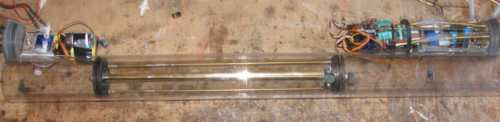
July 19th ======================
I have removed the ballast tank vent valve.
Cleaned all the silicone glue from the valve body, bolts and cylinder.
Lightly sanded the cylinder for better bonding.
Looking at the silicone on the bottom of the valve body, I do not see
any gaps in the layer.
Okay, time to look closer. (10X loop)
Possible gap in valve body itself on the back panel piece.
Cover the outlet hole on the valve body.
Using a brass tube and rubber fuel hose attach to inlet hole on valve
body.
Blow in to hose.
Sure enough the back panel on the valve body has a gap in the layers
of plastic sheet.
There was also an air leak on the port side mounting bolt of the valve
body.
The fix was to build an new valve body and make the base longer.
Longer so I could move the port side mounting hole on the cylinder.
The leak was threads through the cylinder not being cut correctly.
I use stainless bolts to cut threads in my cylinder.
It appears, I use a slightly large bolt to make the threads then uses
a smaller bolt to install.
I looked for the lager bolt but it is no where to be found.
So I will fill the over size hole.
I will drill the new hole to match the new valve body.
Make sure I use the correct bolt to cut the threads.
This part of the fix is done.
The valve body base is made and drilled.
The valve body is in the vise while curing.
I will drill the valve body for the inlet and outlet openings later
today.
Back later
-------------------------------
The ballast tank vent valve body is complete.
Drilled and assembled.
Like all plastic parts, it is in the vise to cure.
July 21st ======================
The last 2 days have been interesting.
First, everyone's break from reading my almost daily posts is over.
My internet connection is through a small 9" dish and it stopped receiving
yesterday.
The repair tech came this morning and replaces a couple of parts and
I am on the internet again.
Progress report.
Yesterday, I completed the ballast tank valve body repair and reinstalled
it on the cylinder.
The cylinder is currently in the kitchen up side down with the ballast
tank filled with water while I watch for leaks.
After the tech left, I was going to go out to the shop and see about
stuffing the electronics in the cylinder.
Opened the back door and the heat rushed in.
I decided to wait until early tomorrow morning to work in the shop.
I think I am at the point to put everything back in the cylinder and
do water testing.
Then in to the hull to trim test.
------------------------------
I did not realize how much e-mail and other messaging I get until I
was without for about 22 hours.
I need to trim some of that down.
July 22nd ======================
Well the ballast tank water leak test went far better than I thought
it would.
Yesterday, I filled the ballast tank with water and left it sitting
in the kitchen so I watch for leaks.
After the net tech left, I got busy with other stuff.
I did not get back to the cylinder and the leak test.
This morning, the ballast tank is still full of water and there are
no signed of water leaking around the ballast tank frame o-rings or from
the vent valve body.
I think it is safe to start putting everything in to the cylinder.
All the electronics has been bench tested and a couple of issues have
been corrected. (plugging in a servo to the Rx backwords was the worst
of it.
The problem now is the heat coming on so early in the morning.
It is beating me up more than I would like.
July 24th ======================
Yesterday was not a good day.
Felt bad all day.
Today is better and I made it out to the shop for a little while.
I fitted the front end cap compression plate.
Drilled and tapped all the control and mounting bolts holes.
Here is the end cap with the control rods sticking through and the o-rings
in place.
The Schreader valve body with the insides removed.
There are 3 holes for the pressure plate bolts.
They have been threaded..
There are 2 brass lined holes for he the 2 safety cables. (not sure
I need them now)
The pressure plate and 3 bolts below the end cap.
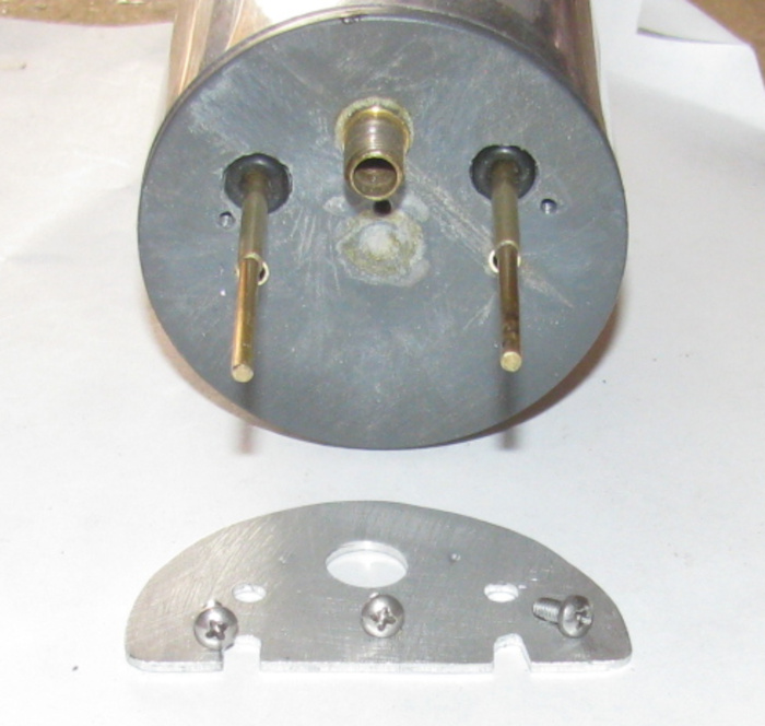
Pressure plate installed with 3 bolts.
Valve cap on.
The 2 safety cable pins are in place just for show. (black knobs with
brass centers)
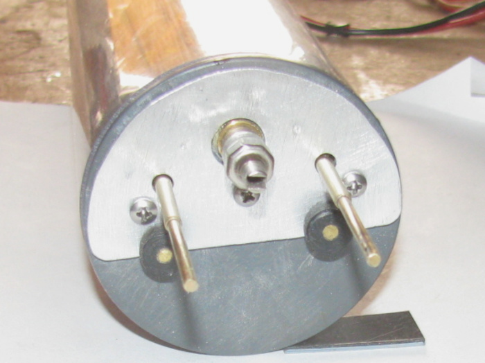
Both bow plane retract and bow plane pitch magnet connectors in place.
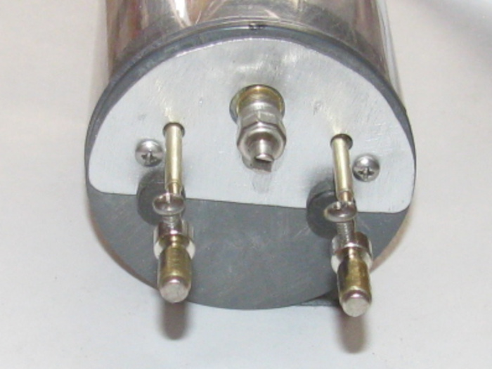
July 25th ======================
Still not feeling my best.
Anyway, out to the shop.
I pulled up my wooden milk crate and sat down.
I decided to work on both the rear and front electronics trays.
There is so much wire!
Servo wires, power wires and wires from the pitch controller and fail
safe board.
Started by pulling the 2 long servo extension wires through the ballast
tank brass tube.
Then the the 2 power wires.
That makes 8 wires through the ballast tank through tube.
Next, I worked on the front electronics tray.
I have wires to 2 servos that are taking up way too much space.
I wrapped the servo wires around the servos and taped them in place
so I had about 1" of wire and plugs to each.
Then I have wires to both batteries. (parallel)
The wires are not a big problem but there are 2 connector plugs.
Long red connector plugs that come on the batteries.
I folded them until I got them next to the end cap under the tray below
the servo control rods.
There is a electronic control board. (now I am thinking I don't know
what it's for)
Going to have to figure it out.
On to the rear electronics tray.
There are 3 servos with all their wires.
There are 2 switches to operate the 2 air pumps.
There is main power to the ESC and it's Rx wires.
There are the 3 motor wires.
There is a circuit board with it's wires.
Spent time routing the wires and tie wrapping in place.
The most important wires where the main motor wires that cross over
the spinning motor case. (motor is an out runner)
I ran the servo plug wires back to the Rx and taped them to the aluminum
tray.
Now, both trays will slide in to the cylinder and nothing touches the
cylinder wall.
The end caps push in to where the cap ledges touch flush all the way
around.
This was enough.
Temperature has made it to 105F and no wind at all.
======================
I could not stand it.
I had to go out and look at the circuit board on the front electronics
tray.
I now know what it is.
I will have to go to my build notebook to see why I put the Fail Safe
circuit on the bow planes.
I will also have to wire the system up and test it to see if the Fail
Safe is on the retract or planes pitch.
A quick trace of the servo wires tells me it may be the bow plane pitch.
-------------------------
Thinking about it, if the signal fails while running submerged, the
Fail Safe on the ballast tank air pumps would be of no help.
They would pump water in to the ballast tanks which are already full.
The mast that is hooked up to the air pumps would be under water so
no air.
Running under water the boat could stay submerged so having the bow
planes Fail Safe in the rise position would bring the air mast up above
the surface and the pumps would start pumping air, surfacing the boat.
If the boat is submerged and the main motor stops, the boat will be
trimmed to bring the mast and 1/4" to 1/2" of the conning tower above the
surface of the water again allowing the air pumps to pump air.
This boat basically is a dynamic diver but able to submerge to the top
of the conning tower.
The bow planes will have no problem pushing the boat down below the
tower and masts.
The boat is also setup so if the BEC turns the main motor off, all the
other equipment will continue to work.
This allows the air pumps to work right down to a dead battery.
I hope the build notebook tells me this is what I did.
July 27th ======================
Feeling a little better.
Out to the shop.
With the 2 servo extensions and power wires through the ballast tank,
it is now time to install the rear electronics tray in to the cylinder.
Connect the 2 power wires, then plug in the two servo wires to the
Rx.
Slide tray in to the cylinder and pull the wires out the front of the
cylinder to take up slack.
Before pushing the end cap in to the cylinder, I cleaned the groove
and o-ring.
Greased the o-ring and put it on the end cap.
Push the end cap in to cylinder and line it up with the indexing marks.
Next I plugged the power wires to the front electronics tray.
I have to turn on the Tx and Rx to check which servo wires go to which
servo.
While I am testing, I checked the inlet and outlet air tubes.
I need to know which is the air from pump to ballast tank.
Got it.
Clean o-ring groove and o-ring.
Grease o-ring and slip on to end cap.
Now I have to bend or fold the wires back on themselves to get them
in the cylinder.
Push end cap in to cylinder and turn to index marks.
With the cylinder electronics in place, I can measure for the 2 safety
wires.
Made them up and covered the brass tube connectors with shrink tube
this time.
I kept getting stuck by the wire ends before.
This fixes that.
Cyliner was pressure tested by blowing in to the cylinder through the
Shreader valve.
Holds pressure.
Next test will be in the water.
Here is the completed cylinder sitting on the hull.
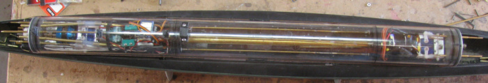
The cylinder assembled, I can mark where the air inlet location is.
And which side it is on.
I need an air tube to the bottom of the cylinder under a flood hole
so the air will go in to the ballast tank.
On the left side there is the air tube outlet in the center of the
ballast tank pin.
The pin goes up in to the ballast tank through a flood hole.
Holds the ballast tank in place.
The right end of the air inlet tube will get a rubber fuel hose that
will be glued to the hull side and brought up to where I can bend it to
connect to the air outlet end cap tube.
Need to let the silicone glue holding the brass air tube cure.
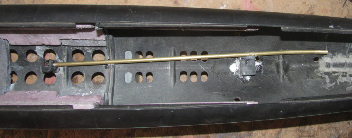
I think this is enough for today.
It's getting warm and I need to try and get better.
July 28th ======================
Back in the shop.
I put the assembled cylinder in to the hull.
I connected the rudder and rear planes magnetic control rods.
I turned ont he Tx and Rx and went about adjusting the length of the
control rods.
Center the rudder and level the rear planes.
Move tot he front and the bow plane.
Connected the magnetic connectors and started adjusting the control
rod length.
Going fine until I moved the retracts from up to down.
The control rod bond a little over half way down.
Looking down through the cylinder I see what might be the issue.
Move the bow planes to center and then worked on the bow plane pitch
control rod.
At center everything is fine but when I moved the planes to up or down,
the control rod bond up as did the retract control rod.
Looking through the cylinder I see the same issue with the pitch control
rod.
Removed the safety cables.
Pulled the front end cap off with the electronics tray.
Here is the electronics tray without the Fail Safe board which sits
on top of the batteries.
The issue is the distance from the end cap control rod bushing to the
servo.
The swing of the servo at center is fine but at either end the control
rod binds in the bushing.
The length of the 1/16" brass rod from the clevis to the 3/16" brass
tube which is inside the busing, does not have an bending play.
No flex at all.
The only thin I can think of is to modify the location of the servos
and batteries.
Move the batteries forward and the servos back as far as I can on the
tray.
That will add almost 2" to the 1/16"control rod.
I checked the batteries in front of the servos and the control rods
will fit with plenty of room on each side of the batteries.
Also, I made a measuring mistake for the location of the control rods
through the end cap.
The control rods need to be moved 3/16" out form where they are now.
This will make the control rod line from the end cap to the servo horn
straighter when the servo is at 45.
This will give equal bending of the 1/16" rod on each side of center.
I thought about making a new cap.
But it is hot right now.
So, I decided to remove the end cap control rod bushings.
Just a matter of setting the small vise up on the bench.
I made a small driving pin.
A tube larger than the inside hole of the bushing and a tube that fits
in the bushings to hold center while I hit it with a hammer.
To make this so much easier, I plugged in the soldering in and heated
it up.
Once it was hot, I held the tip in to the busing fr abut 20 seconds
or so.
Drop the driving pin in to the bushing and tap a couple of times with
my 11 0unce hammer.
Comes right out because the bonding glue is soft.
Drove both out and then cleaned it all up.
It has silicone grease in the o-ring recess.
Once clean, I put tape on the small side of the hole in the end cap.
I put a few drops of glue on the o-ring recess and let it run to the
bottom of the hole.
Did this to both holes slowly until the holes were filled.
I will let cure over nite,
Well a couple of days.
Got things to do away from the house tomorrow.
I will redrill the holes in the end cap after carefully measuring the
locations this time.
I have to cut a new aluminum tray and make all the bends for the batteries
and servos.
This may be a better layout.
I will have room under the servos for all the excess wires.
I only have 4.25" from cap to ballast tank to put all this stuff.
This day after day of heat and not feeling my best is slowing things
down.
Maybe I should have just stop until I felt better.
I just can't help self.
July 29th ======================
Well, I got up very early this morning.
Was in the shop by 5:30am.
I looked over the glue on the end cap.
It is coming long nicely.
The glue requires air moisture to cure so the exposed side has expanded
and hardened up.
I trimmed the expanded glue from the end cap with an Exacto knife.
I turned the cap over and removed the tape.
This side the glue is just like it came from the bottle.
I put the cap on the small vise to make it level.
This side has the Shreader valve sticking out so it will not sit flat
without the Schreader valve clearing the table.
So I will let this cure over night.
I needed to measure the recess in the cap made by my cutter.
I found an old test cap of the same material.
Out to the tool shed and I drilled several 1/8" diameter holes through
the cap.
I placed the cutter in the drill press and cut 1 recessed hole.
I measured this hole with the calipers and then the o-ring.
The recess hole is a little bigger than the o-ring.
On the caps the o-rings were sealing just fine.
But I thought I might make the hole diameters smaller,
I got my Dremel with the grinding wheel.
Spun the cutter and lightly touched the cutter with the grinding wheel.
Removed a little material from the cutter. then tested it on the cap.
Measured the recess and put the o-ring in the recess.
Put a brass tube through the o-ring to see how it tightened up in the
recess.
I did this about 4 or 5 times. (said I did it slowly)
I now have a cutter with the side edges cutting straight holes.
The o-ring is not squeezed in the recess.
The o-ring does not move side to side any more but still is loose enough
to turn in the recess with little effort.
I have had problems with the ballast tank control rod inside the cylinder.
When turning on the system, Tx first then Rx the servo that works the
ballast system, moves to find the signal location.
When it does this, it runs to the extreme pump side of the throw.
This is not good because the cams on the control rod run past the metal
switch levers and when the servo tries to go back to the signal position,
the cams can not pass the switch levers.
This stops the servo travel to the point the servo strips the gear
inside the servo.
I have repairs so many servos.
So I looked it over and I am making a longer plastic barrel that will
go over the control rod that will be longer than the servo through so it
should not go past the end and jam.
I have to make a new guide and move it farther away from the servo
to give the control rod more range to move without running past the switch
levers.
The plastic pieces were cut and are in the vise under pressure to cure.
I ordered more servos from a different manufacturer to see if they hold
up better.
I did this because I could not find the original brand of servos on
sale.
Any way, things are moving ahead.
I might have time tomorrow morning to shape the new switch part.
July 30th ======================
Today, I made the new electronics tray to move the servos back away
from the end cap to get more bend in the control rod so the rod will go
through the bushing straight without binding.
The original tray in the top tray.
I put the servos on the new tray and I set a servo in the original
tray to show the difference.
The measured center to center of servo gear shows a move of 3" +.
The batteries will be put in with the bottom battery laying flat on
it's side and the top battery sitting on edge coming up through the tray.
The control rods will go down each side of the battery.
This gets 1 battery much farther down in the cylinder and about half
the 2nd battery below the center line of the cylinder.
I can put the Pitch Controller on either side of the top battery and
it will be out of the way for the control rods.
I still need to trim about 1/4" off the tray behind the servos to fit.
I still need to measure and drill the 2 holes to mount the tray to the
end cap.
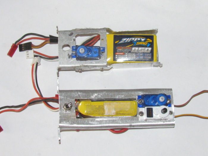
July 31st ======================
I started by cutting a rectangle of very think aluminum.
This will be the new battery tray. (you can see the aluminum battery
tray on the lod electronics tray.
I cut it with scissors.
I bent the 2 90 degree sides,
I left the sides tall so I can cut to height when I get that far.
I drilled the mounting tabs on the electronics tray to match the original.
I want to use the original holes in the end cap.
Done.
Tested the fit and I did not have to enlarge the tray holes to match
up.
Put the electronics tray on the end cap.
Using the old control rods, I found the new location for the tube bushings.
About 3/16" move up and out on the cap.
Marked and drilled the holes for the bushings.
Installed the brass tube bushing and made sure they were square with
the end cap surface.
I need to wedge one to get square.
Removed the bushing and applied glue.
Installed and wedged the one.
Both bushing glued and installed.
Set to the side.
I made the new plastic part that will go on the vent system control
rod that will activate the 2 air pumps.
Making the part was easy.
Lining everything up so it operates smoothly has turned in to a real
project.
There is a 1/8" or 3/16" drop from the end cap bushing line and the
air pump switches.
I thought I would put a small bend in the center brass rod and be done
with it.
The control rod is 1/8" brass tube on each end and has a 1/16" brass
rod in the middle to clean the out runner motor case.
What is causing me problems is the1/16" brass rod.
If flexes just enough for the plastic part on the switch end of the
control rod to move up away from the switch levers.
I had a plastic guide on the original system before I put the1/16"rod
in the middle.
The old guide will not go back were it was do to the longer plastic
piece that hits the switch levers.
So I have to move the guide about 1/2".
Maybe 5/8".
I have been working on that part.
Where I was going to mount it turned out to not be stable.
It moved up and down when the pumps come on.
There is a frame that holds the tray level in the cylinder.
In this photo, the plastic ring is over the 2 pump motors.
I am think I can mount the guide to the under side of that plastic ring.
I am making part to modify the original guide.
The parts are in the vise.
I have glued up several parts and now have to wait for them to cure.
Time to stop.
The temperature gauge on the wall, say 100F and rising.
August 1st ======================
Progress for today.
I cleaned the excess glue off the end cap.
Sanded smooth.
Out to the tool shed and I drilled the o-ring recesses in to the end
cap.
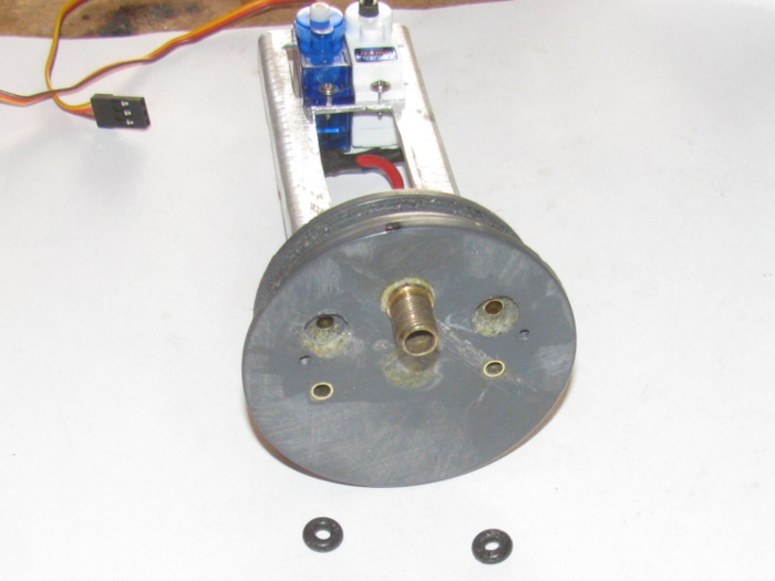
End cap with o-rings in place without the pressure plate.
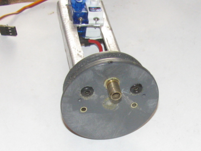
Made 2 new control rods.
The control rods are soldered at the left end and the 1/16" rod can
flex from the servo horn to about 1/2" from the left end of the large brass
tube.
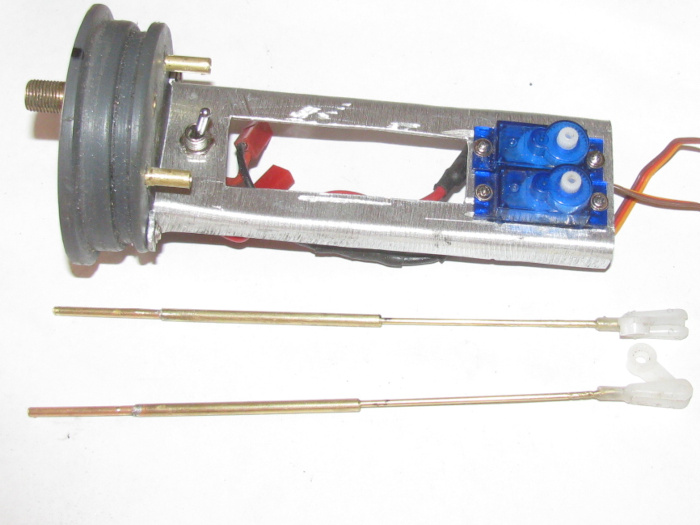
Put in place to measure and then I soldered the parts together.
Tested for air tightness. (leaks)
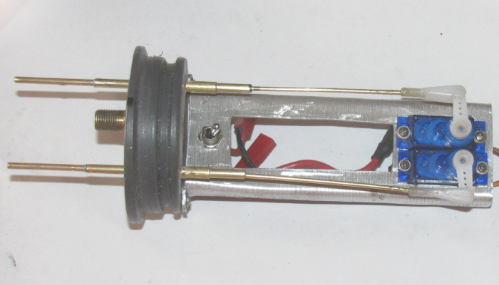
Will finish making the battery tray.
August 2nd ======================
Let's see how the batteries are going to fit.
I made an aluminum tray yesterday for the batteries.
I had planned to place the bottom battery o flat on it's side and then
place the 2nd battery on it's edge.
Sort of a "T" arrangement.
This morning I trimmed the aluminum tray to fit under the electronics
tray with room for 1 battery.
I put the aluminum battery tray under the electronics tray with the
battery in place and slid it in to the test cylinder.
What I was looking for was the battery tray bottom coming down an almost
tuching the cylinder wall.
Pulled the tray out of the cylinder and marked the battery tray against
the electronics tray.
Drill holes in the electronics tray for the 4 very small screws.
Then I marked the battery tray and punched holes with the end of my
small round file. (I have no drill that small)
Place the battery tray in place and forced the screws to thread the
tray holes.
I test fit the top battery through the hole in the electronics tray
and slid it all in to the test cylinder.
Fits nicely with the control rods going down each side of the battery.
BUT looking at it all, it looks like the top battery could sit flat
like the bottom battery making the center of gravity a little lower.
Okay what is needed to make this happen.
Enlarge the hole in the electronics tray so the battery will go through
the hole while flat.
Dremel and grinding wheel in hand, cut the needed width.
File the edges smooth.
Test fit the 2 batteries.
Needs more off one side.
Did it with a file.
Here is what I have.
Side view of battery tray installed on electronics tray.
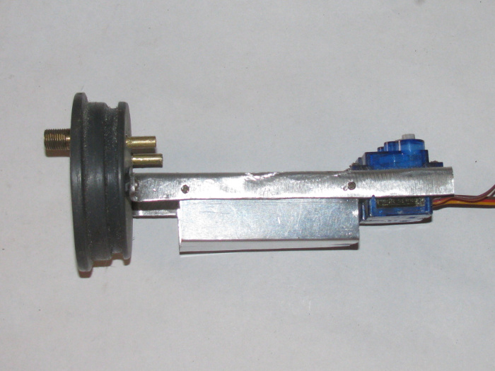
Top view.
There are notches at both ends of the tray.
I don't know how I will run the wires just yet.
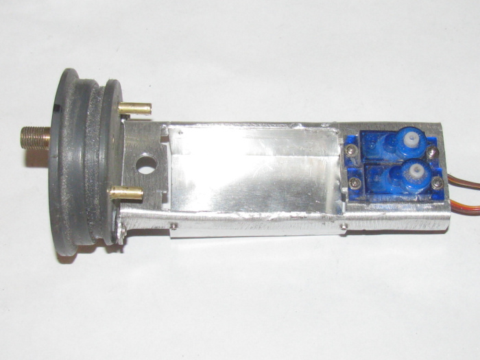
Here both batteries are in place.
One on top of the other.
Control rods in place.
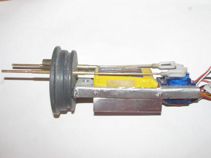
Top view.
You can see the control rods have plenty of clearance.
I need to put the on/off switch back on the electronics tray.
Test fit in cylinder.
Everything looks good.
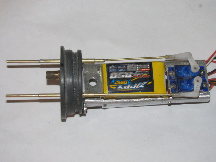
August 3rd ======================
I got a little done before it got too hot.
9:00am 107F. (no wind)
Got the power switch installed.
I tested the Tx and Rx to find working servos for the bow retract and
pitch control.
I have 1 blue servo and I have 3 white servos.
I tested 1 vs the other for turn rate and smoothness to the Tx control
knobs.
If there is a difference, I can not see it.
The difference in the servos is the blue have nylon gears and the white
has mostly brass gears.
I think the pinon is nylon.
Installed the 2 white servos.
Found the control horns for those servos. I think they are the same
as the blue but I did not check.
Grease the control rods and push them through the cap bushings.
Greased from both sides.
The are so much smoother now that everything is lined up.
No binding.
I pushed the front electronics tray in to the cylinder.
The tray stopped when it got to the ballast tank frame.
I thought about cutting some off the electronics tray but then I removed
the tray and dropped my 18" steel ruler in to the cylinder.
With a tap on the end of the ruler the ballast tank frame moved about
3/16". (both frames moved because they are mechanically connected)
This gave me room to push the electronics tray all the way in to the
end cap stop and have just a little gap between the tray and the ballast
tank frame.
There is rood to the rear electronics tray with about 1/2" gap.
Cut two 1/4" wide plastic strips.
By hand I heated the strips between my fingers, one by one.
Slowly bent them in to a 2.5" circle.
Made sure I could get them in to the 2" short cylinder peice.
Glued the two strips together and quickly place them in the cylinder
piece. to hold them in shape.
This ring will be mounted on the end of the front electronics tray
to keep the tray centered in the cylinder.
Made sure everything is turned off and closed up the shop.
Left my Tx on the other day and the battery was dead. Hope it comes
back up.
An update to this morning goings on.
When I went to test the servos I had a problem.
The Tx when switched on, had no power.
Why because the Tx was already on.
The last time I used the Tx was 2 or 3 days ago. Maybe 4.
I got a backup battery and went on with the testing.
When I came in the house I brought the dead battery with me.
Got the charge out and hooked it all up.
Found the correct charging selection for the LiFe 1500mah battery.
Started the charge.
What I got was beeps and an error message saying something like the
cell count was wrong for this setting.
I tried going through the settings to make sure I had it right.
Got same message.
My charge has 2 chargers in it so I tried the other charger.
Same results.
Okay.
I read searched and found information to try.
No luck.
Then I thought I would try charging with out the cell reader and a slow
charge.
I got out the old wall block that you charge the batteries in the Tx.
Plugged it in and got a red charge light.
Left it there for about 3 ours.
Then I noticed the red charge light was out.
Removed the battery and moved it back to the big charger.
This time I did not get the error message.
It actually showed it was charging at 1 amp.
On the individual cells it was reading the charge but not reading the
cell voltage.
I left it on charge for about 2 hours. (watched a movie)
When I checked the charge it showed "Finished".
I put the battery in one of my Tx and turned on the Tx.
The Tx powder up and showed a full 9.6 volts.
I will use this battery for testing and see if I was lucky enough to
save it.
Mean while, I order 3 new batteries.
I did this a couple of months ago but no one had this battery in the
USA and no deliveries from out of country do to virus and USA stopping
imports from certain countries.
The reason I ordered 3.
I have 3 Tx I use with my various boats.
I like having a second Tx in the case with the Tx.
Backup and I have loaned it to other captains that had their Tx batteries
die at the pond.
Yes, I have backup batteries but they are NiCad and I have been moving
away from those to LiFe batteries.
This will give me 2 batteries for each Tx.
Why the move to LiFe batteries?
I had to charge the NiCads a day before going to the pond every time.
These LiFe batteries have been holding a charge for more than 4 months.
When I get read to go to the pond, I put all the batteries on the charge
and I find the backup batteries are still fully charged after 4 months.
The Tx batteries run as long as I run my boats.
My boats run between 3 and 4 hours continuously.
I do not have backup batteries for my boats. 3 to 4 hours is long enough
and I take at least 2 boats.
Well not the time I ran my Akula II down.
I will bet I do not leave a Tx on after using again.
Once should be enough.
August 4th ======================
I am assembling the electronic trays.
The front tray only need the battiers slashed down.
Black tape near the front and then again near the rear of the batteries.
I put a short length of black tape on the longer piece sticky side
facing each other.
This keeps the tap from sticking to the battery labels and makes it
easier to get the batteries out.
On top of the batteries I have room for the Fail Safe board.
Taped the board as I did the batteries so the tape does not stick to
the board.
Checked servo movement and the control rods do not come close to the
batteries or Fail Safe board.
On to the rear electronic tray.
I have to adjust the ballast tank control servo and control rod.
I modified the control rod where it engages the 2 air pump switches.
This took a lot of trial and error to get it right.
With the new plastic piece to operate the switches, the servo can run
to either end full without running off the switch metal levers.
This was a problem.
When I turn on the Rx the servo would cycle to both end causing the
wheel collars to run past the metal switch lever.
When the servo came back to center, the wheel collar would catch on
the end of the lever and strip the gears in the servo.
Problem solved.
I put the pressure plate on the front end cap after greasing the o-rings
and control rods.
I can now put the rear end cap pressure plate on.
I can now put the rear tray in the cylinder after hooking the 2 power
wires and 2 servo extensions.
This will not be done today.
I started about 5:45 am this morning because weather says today is going
to be hot.
I liked it when weather use to get it wrong.
8:00am and it's 103 F in the shop.
Going to make sure everything is turn off and close up the shop.
I think I get to water trials in a day or two.
Got to look at my hospital appointments.
They are starting up again.
Looks like I have this week and next before that happens.
I so want to finish this boat.
I have built and rebuilt the cylinder insides 3 times so far.
First time was good.
Everything works.
I used a roller pump and it was so slow.
It took 3 minutes to surface completely.
Not good enough.
Second time with air pumps.
Surfacing time was about 40 seconds.
But I could not get up to waterline by 1/2".
Not good.
Third time is this time.
I have made the ballast tank bigger by over an inch.
I hollowed out the ballast tank side of the end cap giving me another
1/2" in the ballast tank.
I think I will have plenty of positive buoyancy.
I hope so.
Nothing more lead and more foam can not correct.
Weather says a 10 degree drop on Friday.
I hope they are right, again.
Low to mid 90s is fine with me.
August 5th ======================
I got the wires straightened out on the rear tray.
Slid it in to the cylinder and pulled the extension wires out the front.
Connected the 2 servos and 2 power wires.
Turned on the Tx and Rx.
Testing the rear planes, rudder and ballast tank vent.
It seems to always work on the bench but once in the cylinder something
fails.
The vent valve control rod works fine but the air pump switch is on
and stays on.
Looking at the linkage and I see what might be the problem.
Remove the tray from the cylinder.
I for got to trim the ballast tank control rod plastic guide down to
the centering frame top.
This makes it a little over 1/16" and pushed the frame down which in
turns puts pressure on the control rod moving it down on to the switch
levers.
Remove the ray and file down the plastic guide so it does not stick
up.
While doing this, I disconnected the control rod from the servo horn.
Moving the rod back and forth by hand I see the link from control rod
is more straight in line now.
So I thought I would remove the plastic piece and see if it will work
without it.
The piece is between the servo horn and the brass control rod, has
the long brass pin while making it.
I tested the servo and the direct connection.
It works.
I found a small bolt and nut.
I driller the brass control rod end a little bigger for the bolt and
I threaded the bolt in to the nylon horn then put the nut on with glue.
By removing the plastic piece, the connection has no movement in it.
Control is more positive.
With the Tx and Rx on I adjusted the servo so at full right on the knob
the air pump switches are off.
At center on the mark, one air pump is running.
At full left on the knob, I have two air pumps running.
This is good.
Now to let the glue cure.
------------
Went out to the shop to check on the glue progress.
Solid as a rock.
You might think I could go on but I don't think so.
Opened the door to the shop to be hit in the face with 113 F.
Checked outside temp in shade and sure enough, the cool weather did
not show up today.
Hoping for tomorrow.
Still meeting my 10 minute minimum per day do something to keep the
project moving forward.
August 7th ======================
I was not in the shop yesterday.
Stopped at the post office because I had gotten 2 e-mail messages saying
my orders were delivered.
I ordered servos on July 28th and batteries on August 3rd.
The batteries where USA local (about 60 miles away)
The servos said they were coming from China but I think they have a
USA warehouse somewhere.
Unpacked the servos.
All look like the web page.
Info on packages is correct for what I ordered.
Now for the disaster part of this.
Unpacked the batteries.
Individual boxes.
Inside more plastic bubble wrap packaging.
So much clear tape.
I got the first 2 out and every thing is find.
The third battery was not so lucky.
While cutting the tape, it appears I also got one of the two power
plug wires.
A quick sparking flash and a little smoke.
Finish unwrapping the battery and found the wires were not cut but
the insulation was missing for about 1/2" on both wires.
Also my scissors have a nice 1/4" notch in the middle of the blades.
I ground and sanded the scissors and they are now dedicated shop scissors.
I looked over the battery and between two cells has separated.
I tested the voltage and found it to be correct.
I tried soldering the tabs back together.
No luck.
I will keep this battery and think of some how making a tray for it.
I have 6 good batteries.
So with 3 Tx I have one for each and a backup for each.
----------
On to the boat.
A problem I have had for some time is room for the power wires.
They barely fit through the brass tube going through the ballast tank
with the 2 servo wires.
I made straight inline brass tube connectors which work well but when
they go under the electronics trays, they tend to life the tray slightly.
Before I left the shop on Thursday, I decide to make small connectors.
The original connectors had 1/8" tube plugs going in to large brass
tubes.
Today, I made the new connectors and installed them.
The new connectors have 1/16" brass rod that goes in to a 3/32" brass
tube.
The new connectors are much smaller in physical size.
I ran current test before starting on the smaller wires I have.
They are the same size as the wires that came on the new motors.
Ran at full throttle and with the air pumps.
After 5 minutes I touched the wires and they are not even warm.
I do not run my boats at full throttle and I actually have them programed
at the Tx down to 40%.
In the cylinder the new connectors leave a clearance of about 1/8".
That's it for today.
August 7th ======================
Today started with trying to stuff both electronics trays in to the
cylinder.
Pulled the new power wires through the ballast tank through tube.
Plugged everything in and tested.
Of course I had to change the bow plane servos because they were reversed.
Slid the rear electronics tray in while pulling the servo and power
wires through the ballast tank tube.
No problems at all.
Move to the front tray.
It slides in easily but then all the excess wires started bunching
up.
I turned the tray and got move to the wires to bundle up behind the
tray.
Now of course there is a problem.
The rear tray is all the way in the cylinder but the tray is not sitting
level.
Something is holding the back end up about 1/4".
Took it out and slid the tray in to my short test cylinder.
The tray still is not level but I can look down the cylinder from the
back end.
With a long screw drive I moved wires around but they all seem to be
loose and not touching the cylinder.
So I used the screw drive and pushed down on the electronics tray at
the back.
I could see the tray rocking up and down a little.
Looking through the side, I looked for the fulcrum point.
There it is!
The 2 small battery plugs which are under the battery tray where touching
the tray and the cylinder wall.
Took the tray out part way and stuffed the 2 plugs to the side of the
tray where there is more room.
Slid the tray back in to the test cylinder.
This is the problem because the tray slid in all the way and sits level
with no effort.
Okay take the tray out and see if I can re route the wires to the plugs
so the plugs are in front of the battery tray.
1 plug makes it there but the other one does not.
Needs about 1/2" more wire in length.
Took the tray out and removed the power switch which the 2 plugs are
soldered to.
Found a new plug with the original 8" of wires still on it.
Unsolder the original plug and soldered in the new plug.
Plugged the batteries in to their plugs and taped the plugs in front
othe battery tray, under the power switch.
Also taped down the 2 battery charging balancing wires and plugs.
Checked the tray in the test cylinder.
It dropped right in.
Next is to plug in the 2 servo extensions and power wires.
Put the tray in the cylinder and see if it slides in all the way.
It does and then I tested the system.
Everything works.
Rudder, rear planes, main motor, bow plane retract, bow plane pitch
and ballast tank air pump.
Everything works.
Then I thought, I have never tested the Lost Signal Fail Safe which
should move the bow planes to full rise.
Well the Fail Safe works but I have full retracted bow plane servo.
Pull the tray out of the cylinder and trace the 2 servo wires that are
now taped in place.
Reversed the 2 servo plugs.
All is good now.
I can put the tray in the cylinder.
I need to reinstall the gear box with the o-ring pressure plate.
Then the 2 safety cables.
I have run out of time for today.
I will go out and make sure all the power is off on the Tx and Rx.
Later this evening after the sun goes down and temp drops abut 20 to
30 degrees, I will see about filling the water test tank.
Maybe water test the cylinder tomorrow.
August 9th ======================
All the electronics are in the cylinder.
I have used the fuel hose to blow pressure in to the cylinder and all
seems to be leak free.
This is promising.
But then this build has been a nightmare of broken parts and other progress
stopping issues.
Testing the system on the bent before putting in to the water test tank,
I find that only the secondary air pump activates.
I looked and looked through the cylinder wall and could not find anything
wrong.
So, I have to remove the front tray to pull the wires through to get
the rear tray out of the cylinder.
Done.
This is become an easier and easier jog do to lots of practice.
Now looking at the 2 micro switches that operate the air pumps individually,
the number one switch lever looks odd.
I touch it with a small screw drive to activate it and the metal arm
that push the switch button falls off.
I look through my parts boxes and I find no more switches.
I find the empty package but no switches.
I got to try different brand f switches.
These do not hold up to modifying the lever angle.
The stainless level is bent at 90 degrees coming out of the switch
body and it must be stressed right to it's failing point.
Did a search and found some switches that have the same measurements
and made by different maker.
Okay switch issue taken care of.
I think I will continue with the cylinder leak testing. (I don't need
both air pumps to do this)
The testing will continue tomorrow.
Got real stuff to do this afternoon.
I have been working on they cylinder system so long, I noticed that
the 2 little screws that hold the deck on the hull are not where I put
them so many months ago.
I think I will move the hull off the bench and do a full search with
a flashlight.
The screws are like other screws but they were shortened and they are
painted dark gray on top to match the deck paint.
These are screws that were heated and then turned in to the plastic
to make threads.
Working on the George Washington modification is looking better and
better.
August 11th ======================
I have been doing other stuff I got to thinking that I have gone through
a lot of micro switches trying t make this work.
I have more coming next week but I was thinking maybe I should try
making a brass slider contact unit.
I only need a power wire and 2 contact sliders.
1 for each pump.
So this morning before getting started on other stuff, I cut plastic
pieces and glued them together.
I will let them cure and then turn them to fit in to a small brass
tube. I think it's 1/4" but not sure.
Then make 2 piano wire contacts that will slide on the brass tube and
plastic piece.
The piano wires will be it's own spring to hold contact on the brass
tube.
I have cut the brass tube to length and just waiting to finish the
plastic piece.
Off to do more other stuff.
August 14th ======================
Thought I would check in.
Progress is being made on the Gato.
The issue is the heat.
I try to get out to the shop early in the morning.
But by 9am it is passing 100F in the shop.
Getting old and I can not take the heat any more.
I have been working on a switch for my air pumps.
The ones I bought all failed in some way.
The metal lever breaks off.
The inside contacts stop snapping and stop making contact.
I have gone through several switches.
I order from another manufacture and the will be here this next week.
But I thought I would try to make a brass sliding switch.
I have been cutting plastic and gluing it together.
This has been as slow process.
It is coming along thought.
Anyway, I just wanted everyone to know work is moving along even though
I have not been posting it.
August 14th ======================
Real life has gotten in the way again.
Have not been out in to the shop.
The switch I am making is coming along but very slowly.
Today, at the post office was a package of new switches.
Will see if they will do the job.
But I may not get to it until next week.
I received several appointments at the VA.
Looks like they are going to do follow up surgeries on my wrist, side
of neck and maybe my forehead, again.
I don't have a problem with these surgeries.
They just take up time.
88 miles to the hospital and a couple of days in bandages.
August 18th ======================
I am considering taking up watching grass grow.
Today, I got the ballast tank switches installed and working.
But this was not the fun part.
After installing the switches and control rod, I hooked up the Cylinder
system and proceeded to test everything.
I got as far as turning on the power switch in the cylinder.
Immediately there is smoke.
Pulled the battery plugs to disconnect from system.
Looked for problem.
The Speed Controller was hot to the point the plastic plugs melted.
Removed the speed controller from the electronics tray.
Checked with multi meter.
There appears to be a short in the speed controller.
I checked the other equipment and found no shorts.
Dug through parts box and got a 2 wire servo wire for the battery to
Rx.
Turned on system with no speed controller and all servos work.
Next I checked the ballast tank control rod and switches.
Only need to adjust the center off position then check that the control
rod turns on both switch in order and shut off at center.
All is now good.
I think I have spare speed control of the same brand.
I notice I need to make a new set of wires for battery to power switch.
These are a bit stiff now.
Set everything on the bench because I have VA stuff to do today and
tomorrow.
Well, it is not over yet.
Put the Tx on the other bench where it is out of the way.
As I turned around I hear a load noise.
Looked back where the Tx is and there is a large wrench from the shelf
above the bench.
Tx looks ok.
Tried all the controls.
Yep, a direct hit on the B toggle switch.
It no longer moves.
Opened the Tx case and found small switch parts loose in the case.
Now I am searching for a replacement switch.
I can use the Tx as is because I don't use the "B" switch but I do
not like the hole in the case.
I am thinking seriously about watching grass ground.
Here in the desert, that is about a 3 week time period just after winter
and before summer kills all living grass and small plants.
I think I will make an eight foot by eight foot 2x4 box on the ground
to plant the grass in.
I got enough wild rabbits to not have to mow any of it.
August 28th ======================
Yesterday I received the new smaller power plugs.
They are much smaller than the ones I have been using.
I think they will fit.
I hope to get in to the shop tomorrow for a little while.
This past week and a half has not been going in my favor.
Surgery on neck went well.
The healing has not gone well.
Today I was suppose to get stitches out but do to infection, it will
be next week.
Instead the doctor cut on my eye lid in the corner next to my nose.
Got some heavy duty antibiotics to take for a week..
Got 10 sites froze. Arms and neck and forehead.
I am thinking I am a training aid for new doctors.
Also yesterday, my car decided to let me down in town.
Would not start.
The battery seems to not keep a charge.
Friend brought jumper cables and the car is at home.
Thank goodness for AAA.
They have battery service.
Guy showed up in 40 minutes. (I live 11 minuites from town)
He tested the battery, and starting systems.
As well as the alternator.
He found the battery was not fully charged.
We agreed I would charge the battery disconnected from the car, over
night.
Then hook up cables and see if the battery drains again.
The tech guy also said if the battery drains, he will come back and
replace it with new.
I sure Like my little 1986 Toyota pickup.
It has never let me down in 35 years and about 250,000 miles.'
I have had 5 of these trucks and sell them at 400,000 miles.
They just keep going.
My plan is to get the new plugs in the boat and get the system up and
running.
Then in to the water for leak testing.
I know all the controls worked before I took the system apart to enlarge
the ballast tank.
I might have this boat running for the gathering of SubRonLA on Sept
10th.
September 1st ======================
The past two weeks have not gone well.
The car is still not working right.
The alternator is doing it's job according to the test AAA did on the
car.
I have tested the battery out of the car and it will take a change
and it held it for 5 days on the wooden work bench.
Put the battery back in the car and the car started up on first try.
Let the car sit over night and the next day there is not enough battery
to turn the starter motor.
When hooking up the battery cables, I see a good spark.
There is something not turning off when the car is turned off.
This is not something I can trace on a 2016 car.
Too much electronics.
Next issue. 2 weeks ago I went to VA for 3 appointments on the same
day.
Two were surgeries and one was testing on eyes.
Good news was I thought one surgery was going to be third on my wrist.
Turns out, they already did the third, going two on same day 3 months ago.
First surgery was on my neck.
Was from just under my right ear down my neck 4.5".
Second surgery didn't happen.
They eye testing was for peripheral vision.
A week later I go in to have stitches removed.
This was not done.
The area had become infected and they could not take out stitches because
the swelling might tear open the original surgery cut.
No matter.
They decided to biopsy my left eye lid.
And they gave me some heavy duty antibiotics to take.
So as far as working in t shop, it has not been a priority.
I did get all the wiring completed this morning.
Smaller power wires to go through the ballast tank through tube.
Smaller power plugs which all fit in the limited space I have.
Next will be to trace all the wires to make sure I did not cross something
up.
Then clean up the o-rings and grooves to regrease.
I hope to get in the test tank water in a day or two.
I am just not 100% yet.
Another trip to VA this Friday.
Not sure what I will do with the car.
Maybe charge the battery and take a second battery with cables in case
they are need.
Take the car to the dealer and let them fix it.
September 5th ======================
The stitches are out.
The infection is almost gone.
Feeling better.
In the shop for a little while.
I was checking the wiring from batteries to motor and other electronics.
Well, I must have not been feeling my best as I got 4 main power connectors
reverse.
All the plugs will not connect correctly.
I sat down and slowly removed the soldered plugs and chenged them as
I went.
Checked again and I think I got them corrected.
Now to program the new speed controller.
That went well after I remembered to plug it in to the Rx.
This speed controller is a Robbe unit.
It is made so there is 100% froward and 50% reverse once set.
Well, I got the 100% forwards but it looks like less than 25% reverse.
Tried reprogramming a couple of times with the same results.
I removed the gear box thinking it might be putting too much force
or friction on the main shaft.
Did not help.
I do not think reverse at 25% will be effective except from a stopped
position.
I am going to rethink this speed controller.
I have others I can use to test with but they are too big in physical
size to put in the boat.
I did remove a brass tube bushing from the gear box for the main motor
shaft and the shaft is now supported by the end cap bushing.
Not a problem.
--------------------
As I was leaving the shop, I did not notice the visitor.
Too bad because it got it's head closed in the door and was killed.
I would have taken it out back because this was a good guy.
October 3rd ======================
It has been a month since I updated this thread.
A lot has happened.
I will start with the car.
I charged and test tested the battery out of the car on a wooden table.
I left it there for 5 days.
Put it in the car and the car started up. on first try.
Next morning the battery did not have enough power to turn the starter
motor.
I did this 3 times.
I scheduled the car in to the dealer to find out what was wrong and
get it fix.
Their schedule was so crowded I could not get in until the 29th of
Sept.
Got up early and put the battery of quick charge.
Hooked it up after 20 minutes and started the car. Removed the charger
and off I went to the dealer.
I did not turn car off at the dealer.
The service guy got to me, was first in line, and he did his check
in the turned off the car. It started right up. Turned it off and then
nothing.
He tried a couple more times.
Off he went to the service garage and came back with a tester for the
battery.
The readings he got where very interesting.
The battery is a 850 amp and his readings were 65 and 67 amps.
He tried starting the car again and now the battery read less then
5 amps available.
The battery is shorting out in a cell.
But then it isn't.
The possible answer is something is between two plates and is moving.
Some times not touching and other times shorting out between plates.
They could not do any other testing of the electrical system until the
battery is replaced.
I came home and took my battery to AAA service center and got a new
one.
It took longer than I expected to get a new battery until I realized
the guy was trying to warranty the battery exchange. I told the guy I was
not the original customer of the battery as it came with the use car when
I bought it. This was an outright sale. Now it took 5 minutes to complete.
At home again and put the battery in. So far everything is as it was
before the problems started.
--------------
More during this month.
I got sick for 7 days. No fever, still had my taste and smell. Not
covid.
It was some sort of intestine problem that cleared up on it's own.
I slept most of the time away.
-------------
My truck which is my backup car was also in this mess.
I was going to town but did even make it to the paved road when a side
wall on a rear tire blew.
Change tot he share and went home to get another spare. I have 11 trailers,
all with the same wheels so I have lots of spares.
Two days later, anther tire side wall blew on that truck.
Change to the other spare and continued to two, straight to the tire
shop.
All the tires that were on the truck are the same age so I replaced
all four tires.
-------------
During this time, 2 new speed controllers showed up as well as some
new tools. Allen wrench screw driver types. Both US and metric sizes. All
orders filled and received.
------------
Now to today.
I was in the shop and installed one of the new speed controllers.
Turned on the Tx and Rx and I got the direction correct first time.
Tested the forward and reverse speed. at 100% on Tx settings.
Both directions seem to have the same speed.
Finally after months of messing with this, I have finally found the
right combination of parts.
All the electronics systems work now.
I have one modification I want to do but it is on the aluminum plate
that compresses the seals on the rear end cap.
Matter a cutting some of the plate away and using two small bolts to
compress the plate.
I have been using the gear box bolts to compress the seals and it has
caused binding on the propeller shaft.
Mounting bolts for the plate separate from the gear box will allow
me to set the seal pressure and tighten the gear box down without binding.
As of right now, today, everything seems to be back to normal.
I had thought for month the electrical on the car would have to be
replaced But it only cost me a new battery which was to be replaces anyway.
And the Gato looks like it may get finished this month.
But for the next couple of days, I plan to get more sleep and rest after
such a stressful month. I do mean stressful. Made updated to my Trust.
October 17 ======================
The chaos has gotten back to normal. (sort of)
In the shop this morning I assembled the rear electronics tray and cleaned
the cylinder of all the dust from sitting.
Had high winds and dust was every where for 3 days.
Anyway, the rear compartment has it's equipment installed.
I assembled the front electronics tray and hooked up all the wires.
(servos and power.
Time to test it all.
Everything works but I had the bow planes retract and pitch reversed.
A quick unplug and replug fixed that.
Time to stuff all that extra wire in to the cylinder.
Several tries and I am close but it is not right yet.
Something is putting pressure on the bottom of the tray at the back
making it hard to get the end cap in the cylinder, square.
I am going to have to work on this to see what the problem is.
Maybe I need to remove some of the wire if I can.
Just had a thought.
The issues is having enough wire to pull the rear tray out to get to
the plugs.
The wire sticking out the front when the rear tray is in the cylinder.
Maybe I can make a couple of piano wires that hook to the wires that
will go through the ballast tank through tube and have just enough wire
at the front to hook up the tray.
That could remove about about 8" of 2 servos and 2 power wires.
This is something to check on.
I have 5 days to try to fix this issue.
Next Saturday is a gathering at the lake.
Water trimming only takes a couple of hours to set if my ballast tank
extension is right.
I have 4 full days this next week to work on this.
October 18th ======================
Out to the shop.
Does not look good for getting anything done today.
It is very windy and there is so much dust in the air, I do not think
working with o-rings and grease is a good idea.
So I covered up everything with a plastic bags and will try tomorrow.
October 18th ======================
Out to the shop. (so I thought)
Got tot he shop door and it was locked.
I have never locked the door.
In the house and found the keys for this door.
Key turns both ways but the it does not unlock.
The chaos continues.
Now I have to break in to the shop.
Tried a couple of different methods.
With a flashlight I can see the bolt will not move.
On to brute strength.
Got a couple of long bars and a wedge.
Slowly moved the jam away from the door.
Finally cleared the bolt and the door popped open.
Processed to remove the lock set.
Well, it is stuck and will not slip out.
Okay, time for a couple of wooden blocks and a hammer.
Drove the shaft out off the bolt.
The parts inside the bolt had completely fell apart binding the bolt.
What I have now is a bunch of junk parts.
Guess I will be going to town for a new door handle lock set.
Yes, I look in the tools shed but only found 2 door assemblies that
were incomplete.
Unusable for this project.
Will in the shop, I took the front electronics tray out of the cylinder.
Looked at the wires for cutting.
Might work, so I will try it.
But first I need to get the door working again.
So before I got to town, I am charging the 2 batteries.
If I happen to get all the wires in to the cylinder with all the systems
working, I don't want to take it apart right away.
There should be enough power to water trim and then maybe a hour or
two of run time for the lake it I get it all in there.
I have a plan B.
Take the Skipjack to this Saturday's gathering.
Later in the day ======================
Shop door repaired.
Batteries charge. (less than 10 minutes per battery to charge)
Electronics trays are in the cylinder.
I put the front tray in first instead of the rear tray.
There was more room in front of the rear tray for the extra wires.
Did not have to cut them.
While testing all servos and installing the ballast tank vent mechanical
parts, I ran the Tx battery down to where it was giving out random signals.
Battery now on charger.
The vent mechanical parts or installed but need Tx to adjust travel.
This servo operated the vent valve open to release air and it also
moves to operate 2 air pumps individually depending the distance traveled.
Battery charged for Tx and vent valve mechanical control rod adjusted.
It looks I might be able to water trim tomorrow.
October 20th ======================
Cylinder is closed up.
Filled the test tank out side to do the water trimming.
Everything in the cylinder has been tested and adjusted.
Time to put it in the water to look for leaks.
Right off I see an issue but will continue the test.
10 minutes held at the bottom of the tank.
Lifted it out and looked for water in the front and rear compartments.
No water that I can see.
Back in to the tank for a second time.
10 minutes back out.
I still see no water in the front and rear compartment.
Now I look over the issue and see what I need to do to fix it.
The vent valve body on top of the cylinder leaks air.
It looks like the face of the valve body may not be square to the o-ring
on the valve shut off.
I will need to look closer after I fix the second air leak.
Air is coming from the front side of the body between the valve body
and the cylinder.
This could be I have not gotten the valve body shape exactly right
to fit the cylinder curve.
I removed the body and cleaned off all the silicone caulking.
Now I can see if the curve needs work to fit tighter.
Or just put new silicone on the body and make sure I tighten the 2
bolts evenly and at the same time.
I will lightly sand the cylinder area for the valve body with 600 grit
paper.
Before going that I will check the valve face square to the cylinder
and o-ring shut off part.
I am thinking I will replace the o-ring with new o-ring.
Maybe all this time the old o-ring may have flatten out some on a angle.
I also applied CA glue to the side seams on the valve body just in case.
More to come later today.
------------------
I fit the valve body on the cylinder and did some measuring.
I made sure the bottom of the body fit the curve of the cylinder. (it
does after cleaning all the silicone off)
The angle of the valve body valve side was not 90 degrees to the cylinder.
I files with a fine file and then did some sanding with the 600 grit
paper until I got what looked like 90- degrees.
I then polished the surface with auto body polishing compound to a
nice smooth shiny finish.
I put silicone caulking on the valve body and put it place then put
the two bolts in.
I did not tighten them up all the way.
I held the control rod with the o-ring seal back away from the body
about 1/32" and visually lined up the valve body tot he o-ring seal until
it looked like the o-ring would contact all at the same time.
I will tighten the 2 bolts after the silicone curse which should give
me resistance and allow me to tighten the valve body down and using the
silicone to keep the body square to the o-ring.
Looked over the front and rear compartments for moisture.
There is none.
Tomorrow back in the test tank water.
October 21st ======================
Water tested the cylinder.
The repaired ballast tank vent valve works.
No leaks.
This is where the good news ends.
While testing the other systems everything works as it is suppose to.
While running the air pumps I noticed water in the rear compartment.
I took the cylinder out of the water and drained the ballast tank by
tipping the front up allowing the remaining water to go to the back of
the tank where there is a flood hole right at the frame cap.
Quickly dried off the cylinder and removed the rear end cap to drain
the water out.
About 3/4 ounce.
Was not enough to get up to the electronics.
The rear tray is now out of the cylinder and I will need to disassemble
the tray after I do a test of the air pumps using a bowl of water and long
rubber hoses.
Maybe I will be able to see where the water is coming from.
Until I ran the air pumps, there was no water in the cylinder.
Building this cylinder for the Gato has been nothing but one problem
after another.
For more than a year.
I have thoughts of getting rid of this boat.
Making a surface runner only.
But I think I will set it aside and go back to the George Washington
and finish the refit on it.
I have all the parts.
It's just a matter of building the electronics tray for the 2 new parts.
The GW was a vacuum motor and air bag system.
It will now be an air pump system with a small piston for negative
and positive buoyancy.
But for now, the work on the Gato is stopped.
-------------------
I could not stand having this leak.
So I went back to the shop to see if I could find it.
I disconnected the power wires and 2 servo wires so I could move the
electronics tray around and over and see every bit of it.
I took a short rubber fuel hose and put it on the intake tube coming
out the rear end cap.
I put my finger over the out let and blew in to the fuel hose.
I see a couple of drops of water on the work bench.
Held the tray up to my ear and blew again.
I hear a quite squeaking noise.
Removed the fuel hose from the intake tube and put it on the outlet
tube.
Again blew in to the fuel hoses.
I can again hear the squeaking noise and it is louder.
As near as I can guess, the noise is coming from where the air pumps
are siliconed to the plastic manifold.
To get to the air pumps I need to remove the vent control rod frame.
(2 small screws)
And I need to remove the small servo screw to the vent control rod.
I need to remove the 2 fuel hose that connect the end cap through tubes
to the 2 manifold tubes.
This full exposes the air pumps.
With a finger I find I can move them back and forth easily.
By lifting up on the end away from the manifold I can see the air pumps
starting to release from the silicone.
Okay, lift them up completely.
They are still wires to the activation switches so I need to be careful
not to pull on the wires.
With the pumps up and out of the manifold I can see the surfaces on
the manifold and the air pumps.
The silicone came completely off the manifold plastic.
It appears there was no bond there.
I rubbed the silicone on the pump face and with some effort the silicone
started coming off but required pliers and Exacto knife.
I removed all the silicone and I files and sanded on all the surfaces.
My thought is the silicone is not going to work as I planned.
Making the air pumps removable turns out to be a bad idea.
So, the fix is to clean the surfaces and scuff them up.
Make the air pumps semi permanent.
There are not parts that can be repairs or replace except for the complete
pump assembly.
I decided to try gluing the air pumps to the manifold with Gorilla
glue.
I applied the glue to the manifold face and on the pump face including
the outlets.
Worked the air pumps back down on to the tray and on to the manifold.
I can only hope I did not get glue in the inlet tubes.
I found a piece of gray foam and cut it to fit between the air pump
motors and the 2 servos.
I squeezed the foam in and using a small screw drive got it all the
way down so the foam put straight line pressure on the 2 pumps.
Brought the tray in the house and so I can check on it every so often.
I will check for leaks tomorrow morning while I gather up tools for
Saturday's run at the lake.
I will be taking the Akula II instead of the Skipjack.
It happens to be the box on to of the pile.
October 22nd ======================
Tested the cylinder.
The air pumps no longer leak.
While in the water I pressurized the cylinder by blowing in to the Schreader
valve.
Air bubbles seem at both ends.
Took the cylinder out of the water.
Dried it off.
And set it on the shelf for now.
I have so much time in this cylinder, I could have bought another completed
boat. Twice.
Moved on to the Akula II.
The test tank is full of water so instead of doing some fine trimming
at the lake, I am doing it in the tank.
It is a mater of moving a 1/4 oz lead weight down the side of the piston
cylinder wall.
The boat has/had a slight lean to the right.
So I marked the location of the existing weight.
Cleaned off the silicone.
Cleaned the weight.
Applied a drop of silicone to the weight and reinstalled on the side
of the piston case about 3/8" lower.
I am giving the silicone an hour to setup before testing again.
This boat is a dry hull and the weight is inside the hull.
Letting setup so it does not slide down the side of the piston case.
October 26th ======================
At the lake last Saturday, the Akula II ran very well..
The only trimming needed was mast arrangement.
My masts and periscopes are made from solid brass 1/8" rod.
By picking and choosing masts, I can change the trim of the boat.
Periscopes are near the front of the sail and the antennas are near
the rear.
Most are on the center line of the sail and some are side by side across
the center line.
While running the boat, I watch to see if the boat has any pitch when
the controls are set to level and I watch to see if there is any healing
side to side.
Then I ca bring the boat next to the shoreline and remove or add masts
to change this trim.
This past Saturday, I removed two antenna masts to make the stern come
up slightly and I move one mast from the right side to the left side of
the sail.
Before changing the mast arrangement, I was having to work the rear
planes constantly to keep periscope depth.
After the change, I ran about 1 hour operating only the rudder for
direction changes.
One issue that I have had since I got the transmitter about 3 years
ago is the throttle and rear planes control sticks do not line up side
by side when set to the center neutral notch.
I would move the rear planes to neutral and then h ave to move down
2 notches to get level.
It has been an annoying issue for ever.
Sunday I looked up videos on how to adjust this centering problem.
The first video did not explain how to do this but was on how to go
a lot of neat things with a quad copter.
Watched it and then continued to find what I needed.
Found it.
It turns out to be a simple 1 minute adjustment.
A single screw on a flat stainless spring is loosened and then the
spring is slid in the direction you want the notch to go.
The spring has a large hole or a slot allowing the spring to be moved.
The 2 control sticks are no in line when in neutral notch.
I should have said I have the duel Navy sticks on the left side of Tx.
I got the Akula II out of the transportation box and set it up on the
kitchen table where I leveled the system.
I then checked the rudder for center, the rear planes for level and
the auto leveler for the amount of movement in pitch.
Only needed to adjust the rear planes which got ride of the 2 notches
to level them.
I hope this will rid me of the annoying stick adjustments at the lake.
----------------------
Today, I opened up the Gato cylinder and removed the front and rear
electronics trays.
Last weeks air leaks during water testing is from the 5 o-rings.
I can fix this but would require making another end cap.
Or I can remove the o-rings and go back to the rudder boots.
Much simpler than making a new end cap.
Removed the tray fro the end cap.
Now I hold the soldering iron against one of the control rod through
tubes and the twist with pliers.
It comes right out.
5 minutes and I have all 3 tubes out of the rear cap.
I have to make up the three new through tubes which have a shoulder
for the rubber boots.
Cut brass tube pieced to go from 1/8" to 1/4", 2 short tube pieces
for each control rod.
There are 5 control rod in all.
I cut all the pieces.
I came up short on 1 tube by not having enough of the larger tube.
Guess I will go to town to morrow for brass tube.
I took the end cap out to the tool shed and redrilled the 3 through
tube holes so the new tubes will go through.
I am assembling the through tube pieces.
Should have them in the end cap tomorrow.
October 27th ======================
Got the brass tubing from town.
I have made up 5 through tubes.
I have spun them in the drill press to clean them up and get a fine
shinny finish for the rubber boot fit.
I have installed the 3 tubes in the rear end cap.
The cap is clamped in the small table vise to hold the cap upright
and levels so the glue can cure without running off the cap.
The front cap has been cleaned and washed with soap to get the silicone
grease off.
I will install the tubes Friday. (tomorrow is a VA hospital day)
I have gone through my parts box and found several rubber boots of the
correct size.
I test fit a boot to check clearance to the gear box.
Looks like I need to file a shallow notch on both sides to get clearance
for the boot.
It is the accordion part that touches.
I need about 1/8" more room.
Not a problem, there is enough gear box there that I can remove the
material needed.
The original boots and trough tubes stuck out past the gear box but
this time I have the boots up against the end cap.
The magnetic connectors take up more of the control rod so I need it
as short as I can get it coming out of the end cap.
October 28th ======================
Not much time but I made it out to the shop.
Cleaned off the excess glue on the rear end cap.
Needed to open up 1 through tube where glue got in to the tube while
pushing through the end cap.
Made sure the control rods fit and moved smoothly.
Cleaned up the 2 through tubes for the front end cap.
Covered with glue and installed.
Will cleanup tomorrow.
October 29th ======================
Through tubes have been cleaned up.
Made sure the control rod tubes slide through easily and smoothly.
Checked gear box clearance for boots.
Well it looks like I needed to file on the gear box to get the boots
to fit straight on to through tubes.
Modification to gear box has been done and the boots have clearance
to work.
One more issue to attack.
With the pressure plate that held the o-rings in place no removed,
I need to do something to cover the shaft cup seal.
Not a problem.
The first version of the end cap had rubber boot seals.
Looked on the work bench and found the original gear box cover plate
that has a tab sticking up to cover the cup seal.
Did some measuring and I can just add this cover plate on to the existing
gear box end plate.
I needed to sand off all the paint and old glue from both sides of
the plate and the end of the gear box.
Stuck the 2 propeller secondary shafts in to the gear box to line up
all the holes. (2 output shafts, motor shaft and 2 mounting bolts)
Applied silicone grease to the secondary shafts and pushed through the
gear box.
Applied glue to all surfaces to be glued and slide them together.
Using the secondary shaft dog bone connectors to turn the shafts to
make sure they are straight and run free without binding.
Slowly clamped in to the small table vise.
Checked often that the secondary shafts turn freely.
Got the gear box clamped tight in the vise.
Turned the secondary shafts and slide them out and cleaned the glue
off.
Tomorrow I will start reassembly of the front and rear electronics trays
to the end caps.
October 30th ======================
Got in to the shop this afternoon.
Cleaned up the gear box.
I filed in two areas so the rubber boots will fit and have clearance.
This was a slow process because one bolt is very close to the area
being filed.
Got it.
Moved on to the front tray and end cap.
Mounted the tray to the end cap.
Tested system to see which servo is which.
Problem.
Both worked but the horns did not move.
They both make noise but the gears inside are not engaging.
This was my fault.
I dropped the tray last week and it landed on the control rods.
They did not bend so I thought they might be alright.
I was wrong.
Replace both servos. (I have a different servo to use now)
Checked the original control rods.
Too short.
Looked for the control rods from the original build.
Found them but I have already taken parts from them so they are not
usable for this.
Make new parts from brass tubing and brass rod.
Find new clevis for he ends. (I knew I had gotten a new bag of those
just 2 weeks ago)
Sure do get buried on the bench quickly.
Found them. (I had dropped them in to the empty Gato hull)
In the process of making the 2 new control rods.
That is all the time I had in the shop today.
I have more time tomorrow.
October 31st ======================
This afternoon, I was able to finish cleaning up the excess glue off
the end caps.
Now on to the control rods.
I need to make new ones or extend the existing ones.
The front 2 control rods had to be rebuild to get the needed length.
Made new tubes and soldered them in place after measuring for length.
Put the in the end cap and turned on the system to get the control rods
adjusted.
Then on to the 3 control rods in the rear end cap.
I was able to heat the tubes and lengthen them by pulling the 1/16"
rod out from in side the 1/8" tube which has shim tubes in them.
I had to pull about 3/8" from both ends to have enough inside to make
a good solid connections.
This made the air vent control rod long enough to work.
I had to make 2 new center tubes for the rudder and rear planes to get
the needed length.
Turned on the system to get the control rods adjusted on the servos
for proper movement.
Every thing is hooked up and works correctly.
Next will be to get everything back in the cylinder and tested before
water testing.
Here are the two end caps with control rods in place.
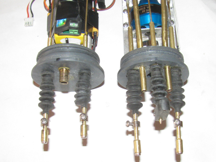
November 2nd ======================
Things have been very slow here.
Yesterday morning I sold an old junk truck to a scrapper.
In the process of removing small wooden junk from the back, I stretched
out and lifted too much.
I pulled muscles in my lower back.
Makes it difficult to stand straight up.
So I did not work in the shop yesterday.
Today I went out and did a little work.
Ended up stopping before I finished what I was doing.
Some where I have muscle relaxing medication for this.
I am not a meds taking kind of guy but this may require the help.
Any way, what I got done.
I turned on the radio system and set the bow planes servo to center
and the retreacts servo to full up.
This will give me a setting point to adjust the control rods coming
out of the end cap.
I turn everything off and put the electronics tray in the cylinder.
The cylinder indexes in the hull on a pin in one of the ballast tank
flood hole.
Once in place the cylinder will not move front to back or twist side
to side.
Now I can measure and adjust the control rods from the forward planes.
Got that done.
Removed the cylinder from the hull and removed the front tray from the
cylinder.
The rear tray has the rudder and rear planes centered so adjusting the
length of the control rods can begin.
However, when I stood up to put the cylinder in the hull, my back was
very insistent that I was done for the day.
I am getting old and I am starting to listen to these messages.
--------------------
What I am adjusting is the length of the control rods coming from the
planes horns.
The control rods are adjusted by bending the front rods and resoldering
the rear rods.
I have 1/4" movement on the control rods coming through the end caps
and they are currently set to center of adjustment.
You can see the adjustment on the photo above.
The magnets I am using are 52N 1/16" diameter.
As I was adjusting the rods, the magnets are strong enough to pull
the end cap part way out of the cylinder when there was a gap between the
magnets. (no o-ring installed)
At least I got something done today.
Hopefully a little more tomorrow.
November 18th ======================
I am still here. <g>
The back issue has gone on for some time but is not better to where
I can stand up and get around.
Not lifting anything at all so as not to back slide.
11 days ago, I was at the VA for more skin cancer surgery.
This was between my nose and eye in the socket.
Does not hurt but the bandage covering the hole has my eye lid doing
strange things.
Got the report on the area removed which came back negative. (good)
Had other life stuff to do and get through.
I hope to be back in the shop this coming Saturday.
I want to get the rear electronics tray back in the cylinder and the
3 control rods measured and adjusted.
I will do what I can as long as I do not hurt myself at all.
November 21st ======================
Finally back in to the shop.
Assembling the cylinder.
The front goes in first now instead of the rear.
This takes care of all the extra wire length to get through the ballast
tank tube.
Before all the extra wires would bunch up behind the tray and stop
it from going in all the way with out a lot of trouble to get it to fit.
Now that the front tray slips in all the way with out the wire issues,
I found another issue.
The tray is aluminum and when in the cylinder the battery tray bottom
touches the cylinder not letting the tray sit straight.
Removed the tray from the cylinder and measured it to the end cap.
There is room to move the left mounting screw up 1/8" on the end cap.
Drilled the hole for the screw and moved it.
While drilling the hole I noticed the tray was not sitting at 90 degrees
to the end cap.
Put the tray in to the short test cylinder.
Yep it was not 90 degrees.
To fix this, it was a matter of bending the mounting tabs on the tray
while on the end cap.
When in the cylinder the end cap did not flush up on the cylinder having
a 1/8" gap on one side.
After straightening the tray, the cap sits flush on the cylinder end.
Now to the rear tray.
This tray was okay before and it slides right in.
After all the small modification to the tray, I have abut 1" empty
room between the tray and the ballast tank frame.
All the extra wires fit there without pushing on the tray.
So all the electronics are in the cylinder and the 2 safety cables are
installed.
Time to power up the system and test everything.
Test was good.
Put the cylinder in to the hull.
Starting at the front I have to adjust the control rod lengths.
They are too long after going back to the boot seals.
The bow planes retract and pitch control rods are about 3/8" to long.
These control rods have large bends in the to get the rods from centerline
at the bow planes control horns to the cylinder push rods which are about
3/4" off center to each side.
Adjusting was a matter of changing the bends while having he system
turned on so I could adjust for the servo travel.
Done.
Now to the rear control rods.
Rudder and rear planes.
These rods are almost straight so to adjust them I will be cutting
the shorter.
With the system on and all controls center, I can see the over lap of
the control rod magnets.
The rudder was 1/2" to long and the rear planes was 3/8" to long.
I glue the brass rods in to the nylon clevis are make a flat area on
the rods.
I was able to twist on clevis off but the other rod broke right at
the end of the clevis.
Cleaned the glue of and put the clevis on the rods and put back in the
hull.
This I can move the clevis on the rods to find center and m ark the
rods.
Taken out of the hull, I apply glue and slip the clevis n to the rods.
This requires pliers due to the flatten rod ends.
I have about 3/8" of adjustment on the rod magnet connectors so close
is good.
I can also bend the rods if need be.
The glue on the rods is curing in the small vise.
Will install tomorrow.
Got to remember to put the 2 rubber boots on these control rods before
installing.
November 23rd ======================
The rudder and rear planes control rods have been measured and cut.
Put the cylinder int he hull and with the radio on I adjusted the control
rod lengths.
Put the ballast tank control pieces back on the control rod.
Yes, I remembered to put the rubber boots on the control rods.
Maybe tomorrow or Friday I will do the in water testing or the cylinder.
If that goes okay then trim the boat.
November 28th ======================
Update:
Cylinder has been water tested.
In to the test tank and no leaks after 5 minutes.
Back in to the tank with weights to hold it down at 15". Bottom of
tank.
Left it there for 3 hours. (forgot it)
No leaks.
Out of the tank and left dry outside in the shade.
Put the cylinder in the hull.
Installed the two propeller dog bone connectors.
Connect 2 air hoses. (inlet/outlet)
Snap all magnetic connectors together.
Test all controls. (Good)
In to the test tank.
Vent the ballast tank.
Took about 10 seconds to fully empty the ballast tank.
Time to turn on the air pumps.
Slowly turn the control knob until the first pump comes on.
Then turn all the way for both air pumps.
This is not exciting at all.
I can see the boat coming up but it looks like it is going to take
a long time.
Lifted the boat out of the water.
Removed the deck so I can see the cylinder and it's workings.
Back in to the water.
Fill the ballast tank by venting.
Again 10 seconds.
Now the air pumps.
First pump is turned on.
I see the air bubble coming in to the ballast tank.
Turn on the second air pump.
More bubbles.
So the system works.
However the air pumps are not producing the volume needed to bring
the boat up.
After 2 minutes the boat is up to about half way on the deck sides.
This will not do.
I check the air hoses for obstructions.
None found.
Just not enough volume.
At this point I do not know if the ballast tank is large enough to bring
the boat up to the waterline which was the reason for this last modification.
Enlarged the ballast tank for more positive buoyancy.
I have decide to shelf the Gato for now.
I do not seem to have the correct equipment to make this work properly.
Going to have to rethink this project.
This system was also to see if I could use it in the George Washington.
It does not look good.
I have 2 working subs and a rescue barge I can run.
So I think I will let the Gato and GW sit for a while and ask question
of others at the lake on their systems.
The problem is the small diameter of the Gato and GW cylinders.
The pumps I have are all to big to fit.
I am going to look in to this system.
https://www.youtube.com/watch?v=RqnxuMlmhkA
November 29th ======================
Well as usual, I woke up with thoughts on what the problems in the Gato
might be.
I got some time late this morning so out to the shop I went.
I removed the rear electronics tray.
I removed the Rx, air pump section of the tray.
Disassembled the parts from the tray to get to the pumps.
Carefully with an Exacto knife, I slowly cut the glue holding the air
pumps to the manifold.
Cleaned the glue of the pump housings and wire brushed to get it all
off.
With the air pumps clean, I can see a possible problem.
Each pump has a inlet and outlet for air hoses to attach.
3 of the four had glue in the holes. (glue is an expanding glue and
it appears it expanded between the air pump and manifold)
These little air pumps are held together with a single plastic clip.
Remove it and the pump comes apart.
I didn't want to drill or push the glue in to the pump and damage the
rubber parts.
This way I could push or drill from the inside out keeping the dried
glue out of the pump.
At this point I have other things to do so I will test the pumps later
today.
I have a spare that I will test first to compare the other two pumps
to.
But the glue in the inlet/outlet tubes would definitely reduce the air
volume.
It looks like pump #1 was producing zero air output.
#2 produce a restricted air output.
If this is the case, I will build a new air pump tray section.
I will most likely wire the two pumps together so they both come on
at once.
This will remove one switch from the system and the associated plastic
mounting brackets.
I could possibly gain another 1/2" of room in the cylinder.
All this depends on the testing the pumps for volume in to a test cylinder
I have I can change the volume to match the Gato ballast tank.
Then I can time air filling tank.
----------------
This mornings problems are the air pumps.
After removing them from the tray and cleaned up I started to test
them but found my test battery needed charging.
Got that done and the other stuff not sub related.
I have tested the air pumps.
I started with the new pump so I would have something to use as a baseline.
1st air pump from boat tested and work as the new pump.
It looked to have the same volume of air coming from it.
Moved on to the second air pump.
This was not the same.
It immediately pumped water out of the intake.
That's not right.
I hooked the hose to the intake and tried again.
Air came out in the bowl of water.
Had good volume.
But this pump is using the inlet as the outlet.
Opened it up and changed the parts around 180 degrees.
Tested again.
This did not go well.
It still pumped water out the outlet and air out the inlet.
Well now to get in to it.
I got my 10x magnifying loop.
Looked over the outside of the case to make sure I had the power wires
on the correct terminals. (didn't matter which way they were hooked up)
Opened up the air pump.
Laid the parts out in order of disassembly.
Now I took the other air pump and disassembled it.
I could see right away that the parts where not installed the same.
I carefully put the pump that was incorrect together the same as the
good pump.
Reassembled both.
Tested again the good pump.
Still good. (amazing)
The pump that was backwards, now it pumps correctly or the same as the
other 2 good pumps.
I have all 3 pumps pumping correctly.
Put the new pump back in the GW box of parts where it will be used.
As far as volume of air bubbles.
They all produce what looks to be the same volume.
So much more than yesterdays tank test.
I will modify the air pump tray and reinstall on the electronics tray.
I will not use the plastic manifold but instead use rubber hose and
tee fittings.
This gets rid of about 2 oz of plastic and gains me a little more than
1/2" on the tray.
I will use 2 switch instead of two.
This reduces the weight even more.
Yesterday during the tank test, during dive and surfacing, I noticed
the hull rolling slightly each time as CG moved. (both directions)
This tells me I need to look under the deck and see if I can remove
more material from the support frame. (the above waterline stuff)
I think because I changed the speed controller, this one is thinner
and shorter, I may be able to change the location of the Rx.
I may be able to stand it on end .
I will see if this is possible.
If so, I can shorten the tray another 3/4". (maybe)
If that is the case, I could make the ballast tank another 3/4" longer.
(not sure I need it because I have already lengthen it 1".
Today's developments have save the boat from being shelved for the time
being.
December 1st ======================
Things are going slow.
Not much time in the shop.
The Rear equipment tray is made in section.
This happened when I could not get the main motor to align with the
propeller shaft.
The shaft would bind up and stop the motor.
What I found was not what I thought.
I thought the motor to shaft connector was off center.
When I removed sections of the tray, the motor ran find with no binding.
So I slowly added sections and found the problem.
One of the servos, the rudder, would touch the cylinder as the servo
moved.
Mostly at center, the servo was touching and this pushed that section
of tray down about 1/16".
This was more than enough to bend the motor section which was part
of the main tray at that time.
I made a separate aluminum section for just the motor to connect to
the end cap.
The servo touching the cylinder wall still moved the tray but not the
motor tray.
No more motor binding.
The tray is in 3 sections.
Motor tray which is separate and not touching the other tray sections.
The center section has the rudder and rear planes servos mounted and
the auto pitch level controller.
The rear section had the 2 air pumps, 2 switches, Rx, and speed controller
on it.
I have removed the 2 section that do not have the motor on it.
The was a bend in this tray to drop the air pumps down 1/4".
I have straightened out this tray.
By doing this, I can make the tray 1/2" shorter.
I am now working to make some sort of manifold for the 2 air pumps.
I had made one before but the thing was large and heavy.
By turning the air pumps around 180 degrees, I loose 3/8" of plastic
manifold and two 3" brass tubes. (weight gone)
The new manifold will have two 3/8" long brass tubes of which half will
be in the manifold.
I have cut out the pieces of plastic for the new manifold and bonded
pieces in to 3 sections.
I have drilled the pump pieces so the 2 pumps fit in to the 4 holes.
(tight)
A little silicone glue will hold them in place.
I use silicone because it is easier to remove should I need to remove
an air pump.
Waiting for the plastic bond to cure.
I will then put 2 grooves in the center section of the manifold. (air
channels)
I may gt back out to the shop for a couple of hours on Friday afternoon.
This time of year, time gets away doing other things.
SubRonLA has a gathering coming up in January.
I hope to have the Gato there.
December 3rd ======================
Assembling the air manifold.
Here are the two pumps.
The air pump mounting bracket bonded to the air channel t of the manifold.
The air inlet/outlet cover plate.
And the two brass tubes for the rubber air hoses.
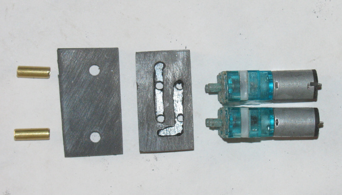
The two air pumps on the mounting plate. (not yet glued in place)
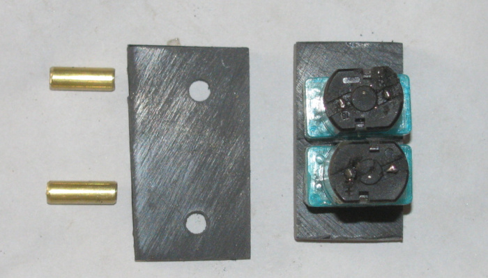
The two brass inlet/outlet tubes glues in place with silicone glue.
(for removal if that becomes necessary)
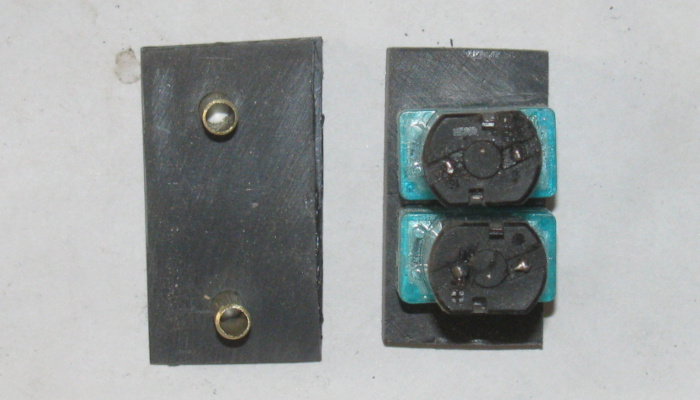
Side view.
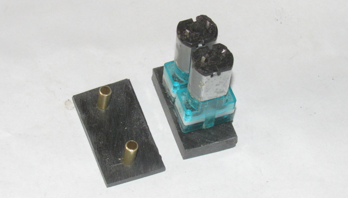
Manifold with the air pumps. (cover plate not glued. cover plate needs
to be trimmed to fit properly)
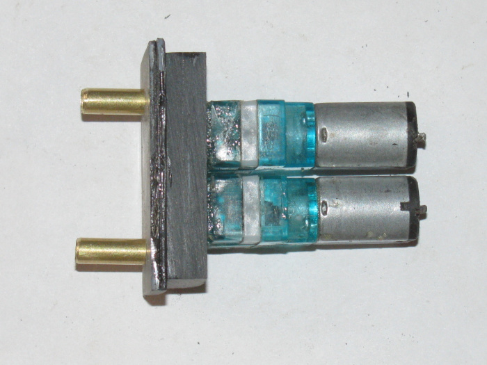
Side view.
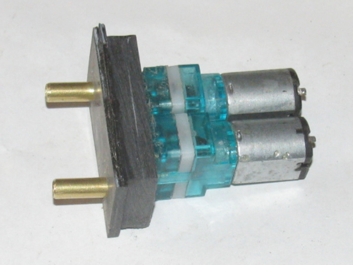
All the plastic parts have had cement bond applied and the parts are
currently in the vise and clamps to cure.
December 5th ======================
I got about 2 hours in the shop this afternoon.
I trimmed the air pump manifold and rounded off the two top corners
to fit the cylinder curve.
I cut a new aluminum tray for the rudder, rear planes and ballast servos.
I made it longer so I could mount the Rx, speed controller and ballast
tank air pump switch.
I cut the three servo holes in tot he plate and files them until they
fit.
Drilled the screw holds and slowly taped them for the screws. (broke
4 or 5 screws doing this)
The new plate will be 1/4" closer tot he motor case giving me 1/4" more
room.
The servos are mounted for the time being.
I am done for now. (my hands hurt from tapping those screws in to the
plate)
Next I need to figure out where the ballast tank switch will go and
how to mount it before I can do the Rx and speed controller.
December 9th ======================
Too much other stuff going on.
But I have been in the shop a couple of times this week for a few minutes
at a time.
I have found where to put the ballast tank air pump switch.
Had to make a plastic mounting bracket for it.
Got the air pump manifold built (plastic) and mounted it to the aluminum
tray.
Started to wire the 2 air pumps to the switch then realized that needs
to wait until air pumps are installed and not just sitting in place.
I now have to figure out how to get the Rx and the speed control mounted
in the little room I have left on the tray.
I think if I cut some of the aluminum under the air pumps (a sort of
big notch) I can raise the Rx up about 3/8".
This will let me put the speed controller under the Rx.
But I have the time to work in the shop today but cold weather has come
in and my hands are starting to hurt.
So, I hope for warmer weather tomorrow.
Slowly things are going together.
December 12th ======================
I have not found time to get in to the shop.
A couple of days ago, I put the Rx and speed controller with the tray
full of servos and air manifold in the short test cylinder.
This showed me I had the length but not the vertical room for both.
At that time the Rx was under the aluminum tray and the only place
for the speed controller would be under the Rx.
It just would not fit.
But today while coming home, I had a thought on how to get more room
in the rear compartment.
There was a gap between the back of the air pumps and the aluminum
tray.
When I got home I went out to the shop and did some real measuring.
If I raised the Rx to within 1/16" of the air pumps, I could get about
1/4" more under the Rx.
It looks like the speed controller might slip in under the Rx then.
Okay, I marked the aluminum tray where the air pump manifold was.
I needed to remove aluminum from the tray up to the manifold base.
Marked for the 2 cuts I could do on the band saw.
Brought it back to the shop and with the Dremel grinding wheel, I did
the cut in the middle of the tray.
Mounted the air manifold back on the tray and filed the tray to the
manifold edge.
Holding the Rx in place, I measured for the thin aluminum sheet to hold
the Rx up near the air pumps.
I was going to cut the piece out of the sheet I have but then I think
maybe I can recut the original piece I had made.
Slipped in to the tray slot and it fit.
It was too tall which is a good thing because I can cut material off
to make it fit.
Modified the aluminum piece and check fit it.
Had to make a small change.
That did it.
Cleaned the aluminum pieces.
The tray and the mounting bracket.
With that done, I applied the black silicone glue. (high temp but still
flexible)
Found 2 small wooden blocks and then set it in the small vise and clamped
it to cure.
The time I had in the shop went by quickly.
I hope this fixes my room issues.
Next time in the shop, I have to take time to sweep the floor and sift
through all the floor sweeping to find several small bolts, nuts and screws
that I dropped off the bench and could not find.
Most of these parts are stainless, non magnetic so I have to hand check
it all to find these parts.
--------------------------
Think about the trimming of the boat, one issue is the stern is heavy
and I have to put weight in the bow to lower it to make the boat level.
I am thinking I may have to removes some of the under deck plastic
frame in the stern.
This should raise the stern a little and it should lessen the roll
as the two CGs come together during diving and surfacing.
December 13th ======================
I ventured out to the shop.
49 degrees.
I removed the tray from small vise
It looks like the silicone glue did it's job.
A little pushing and pulling on the glue part and it is secure.
I slipped the Rx in to the bracket and it fits snugly and it is level
to the tray.
Looks good.
I measure correctly for length.
Okay, it's too cold for me out here.
Weather for the next few days is showing nothing higher than 50 degrees
with mid twenties for the low.
Also it says good chance of rain and freezing rain.
Tomorrow, if I get out to the shop, I plan to close the roof vent and
clean up the heater of the dust and dirt.
Fire it up and let it burn off any internal dust.
Get it ready to use so I can work in the shop.
December 19th ======================
In to the shop.
Still to cold to work but I need to get something done. (currently
51F in the shop)
I was thinking I needed to lengthen the speed controller wires about
1" to get the speed controller farther forward.
Or lengthen the wires 4" so I could turn the speed controller 180 degrees.
Problem is the speed controller has an adjustment screw on one end
causing a 3/16" rise or bump in the covering.
This bump raises the speed controller up where it touches the cylinder
wall and because of this, there is not enough room.
By turning the speed controller around, I can get this bump in to an
area that has free space.
To measure everything, I slide the tray in to a short cylinder piece
I use to test fit.
I don't want to risk dropping the full cylinder while test fitting.
The way the brackets mount to the tray is 4 little bolts.
The rudder servo and rear planes servo mount under the tray sticking
through the tray.
The ballast tank vent servo mounts on top of the tray.
This gives me 1/4" separation up and down for the control rods to pass
over one another.
While trying to fit the speed controller I was having issues fitting
it where I thought it should go.
But all this testing was with the servos not on the tray.
I decided to put all three servos on the tray and found I needed to
change the tray from the top side of the mounting brackets to the bottom.
I slide the tray and speed controller in to the test cylinder.
I was pushing the speed controller around with a long screw drive to
get it where I thought it would go.
I didn't but while moving the speed controller I saw that if I moved
it back between the Rx and servos, it FIT.
I was trying to get the speed controller under the Rx so I would would
have a flat mounting surface. (double face tape or silicone glue)
Now where it fits, one end is under the ballast tank servo and the
other end is located so the 3 wires are at the Rx tray bottom.
I can glue the wires to the bottom of the Rx bracket and the other end
to the servo bottom.
Had I not put all the equipment in the test cylinder, I might not have
ever seen this location for the speed controller.
It is odd to have the speed controller sort of suspended at each end
instead of solidly touch to mount it.
I dropped one of the small bolts on to the floor and it is too cold
to craw around to look for it.
Tomorrow I will go to the hardware store and buy a half dozen or so
small bolts.
I will find all the dropped parts when the weather turns warm and I
clean the floor.
Okay, my hands are not feeling the parts so in to the house I go.
I go something done today.
It was major step.
Next I will silicone glue the speed controller in place after I check
it a couple more times.
That leaves only the pitch controller to mount and I have a place for
it.
Before I install all of this, I will take photos.
December 30th ======================
The weather is not cooperating at all.
The highs are in the low 50's but most of the time in the high 40's.
Yesterday, a storm has come in with rain and a high today of 36F.
I did pick up the missing bolt and nut.
Turned out the issue I thought was the bolt, standard or metric was
not the bolt at all.
It was the nut was damaged from both sides so the bolt would not start
in to the threads.
Later today I will be out in the shop, while there I will get the short
test cylinder and the rear tray, speed controller and pitch controller
and bring them in the house whereit is war and do the assembly.
Shouldn't take long, maybe 20 to 30 minutes once I get the parts war.
Then I can bring the boat cylinder inside and put the tray in.
----------------------------
I have been thinking about the George Washington.
I have all the parts, the new cylinder and the new ballast system.
All the parts for the most part are the original parts that once made
the boat run.
The ballast system is new and the parts have been cut to length.
I just need to make the front end cap for the ballast tank.
I have an idea to put a servo on it with a rubber diaphragm.
The ballast system will be an air pump that will breath through the
top of the sail.
So the boat will be trimmed with 1/4" of the sail above the surface.
Now the diaphragm will make the boat neutral when centered.
Positive when moved in to the ballast tank.
And hopefully just a little negative when the moved out.
I hope the ballast system will run completely empty on the surface.
sail above the surface when fully flooded.
And the diaphragm will make the boat positive to get air mast out of
the water and negative to run submerged.
Safety being the diaphragm being able to make the boat negative to positive.
Yep, I have plans for the GW as soon as I can get the Gato off the bench.
January 1st =====2022=================
New year.
Weather cleared up and is sort of warm. (42F)
I finished sealing up the shop for winter a day or two ago.
Got out to the shop and turned on the heater.
In a few minutes the temp in the shop was up to 55F.
I can work in this.
I made a plastic bracket to mount the speed controller to.
As I was test fitting, I held the tray up to the cylinder. (not the
short test piece)
What I saw was unexpected.
All this resizing parts of the tray that I was trying to get 1/2" between
the tray and the ballast tank end turned out to be 1.25"+.
This allowed me to move the Rx 3/8" forward in it's bracket.
The speed controller, now drops in place without having to be at a
slight angle.
I can also move the speed controller off center to one side about 3/8".
This move makes room for the pitch controller to sit beside the speed
controller and not be next to the servo.
Made a plastic piece to hold the Rx forward and it bolts to the tray
using the water pump bracket bolts.
Using this plastic bracket, I can now make plastic bracket to hold
the pitch controller at the correct angle and get to the adjustment screw.
The plastic bracket was made and installed.
The Rx was set in place and a couple of dabs of silicone glue to hold
it in place where applied.
A small clamp was used to hold in place during curing.
This all went so well, it took maybe 45 minutes.
Tomorrow if the weather holds, though with the shop sealed up and the
heater filled yesterday, I can work out there in any weather, I will make
the pitch controller bracket and get it mounted.
That will finish the tray modifications I have been fighting with for
the last few months or longer.
Now I need to go out to the shop and make sure I turned off the heater.
January 2nd ======================
Today is cold. (for me) 43F outside.
Out to the shop.
Turned on the heater.
Going to make a bracket for the speed controller.
Started cutting up plastic pieces when I spotted an old aluminum bracket
from who knows what.
It was the right shape but a little long.
Cut it shorter with scissors.
Straighten one bend out and then rebent it.
Cut a little off the lower mounting leg.
This is thin aluminum. 1/64" or less. Works nicely for small brackets.
It fits between the vent servo and the Rx.
It is to hold the speed controller up high enough to have the wires
coming out each end up over the servo bottom and the Rx bottom. (Actually
below them.)
After a few minutes I got it looking good so I spread some silicone
glue on the bracket tabs and then the speed controller.
Pressed both parts on to the air pump plastic bracket.
Made sure both parts where straight and doing what they were suppose
to.
Put a 3 pound weight on the on the bench and will let it cure.
With the speed controller in place, I was able to measure for the pitch
controller bracket.
Made the bracket for the pitch controller.
I missed lunch to do this, so inside I go.
Checking what I need to do tomorrow, I may have a couple of hours I
can get out to the shop.
Progress is slow but progress is being made. . . again.
January 5th ======================
I had a plan but we all know how that goes.
House furnace broke.
I had to figure out what was wrong and get parts.
Turned out to be a blower heat limit switch.
Drove 90+ miles round trip to a company that on the phone said they
had it in stock.
Turns out they did not have it in stock and needed to be ordered.
Got home and found the part for half price including shipping and it
was here in 2 days.
To replace this switch took all off 4 minutes.
8 screws of which 2 held the switch to the blower housing.
------------
Yesterday, I was in the shop.
Turned out to not be a good day.
I found that the ballast tank control rod through the end cap was bent
enough to stop the control rod from going through the end cap.
Looked it over and decided to try and bent it back in to place.
With a stainless solid rod that fit in to the 1/8" brass tube, I bent
the tube slowly and a little at a time check as I went.
I stopped when I got the control rod to go through.
It was a little tight and I decided to stop there.
---------------
Okay, out to the shop this afternoon.
Turned on the shop heater and started in on the tray.
I checked the ballast tank control rod through the end cap.
It goes through but was tight in spots.
I did not like this so I did a little more bending.
This worked out well.
I got the brass tube straight enough that the control rod drops through
on it's own weight.
Now back to the issue of the control rod touching the top of the main
motor case.
The motor itself still spins but there is pressure on the case from
the control rod.
The control rod through the end cap is 1/8" band there is 1/16" brass
rod to the servo.
The 1/16" rod is for flex ability.
The 1/16" rod goes over the motor.
I see a solution.
Bend the 1/16" rod right at the 1/8" tubing.
The bend will be just enough to off set the rod but not extend above
the 1/8" tube.
This allows the tube to move back in to the end cap tube long with
the 1/16" rod.
The hope is to have the control rod 1/8" tube and about 3/8" of the
1/16" rod go in to the tube through the end cap.
Only the 1/16" rod will be over the motor and still have full movement
of the control rod.
Took a couple of times but I got the1/16" rod in to the end cap tube
with no binding or friction.
Next, I bent the other end of the 1/16" with a nylon clevis down to
met the servo horn.
Got it.
This has to be straight because the nylon clevis will be touching the
ballast tank air pump switch to turn on the air pumps.
Moved on to wiring the 2 air pumps, through the switch, to the Rx plug
to power the pumps when the servo clevis depresses the switch.
Finished the switch plastic bracket.
With the control rod in place, I can install the bracket on the air
pump plastic tray and center the switch lever on the clevis.
Glued in place and clamped.
This should finish all the equipment on the electronics tray.
My plan to try to finish this by this weekend is not going to happen.
It might but I would be rushing and every time I rush, this go terribly
wrong.
So I will continue but not put a deadline on completion for now.
Besides my test tank water is still freezing over night and thawing
out about 1pm to 2pm.
|