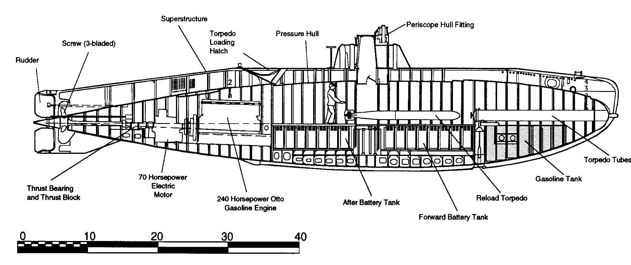
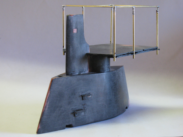
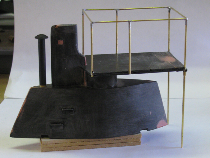
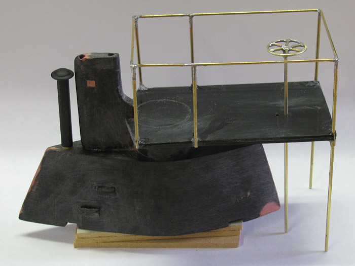
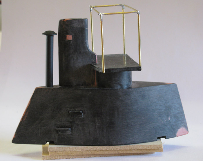
| The Hull ...............
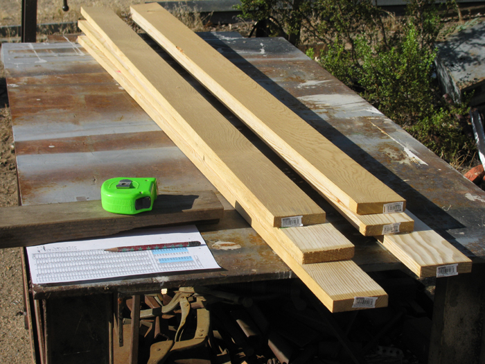
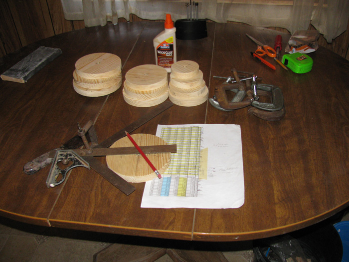
I have made a spread sheet of the frame stations and station diameters.
I can no longer put this off.
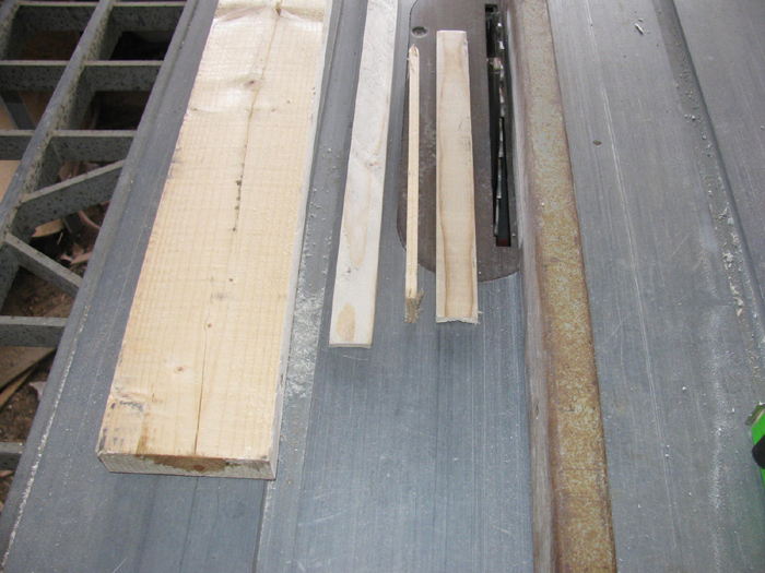
Over to the table saw I go.
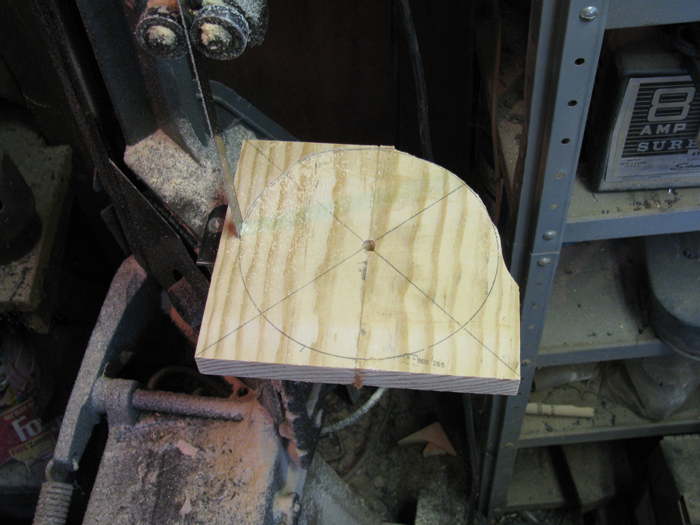
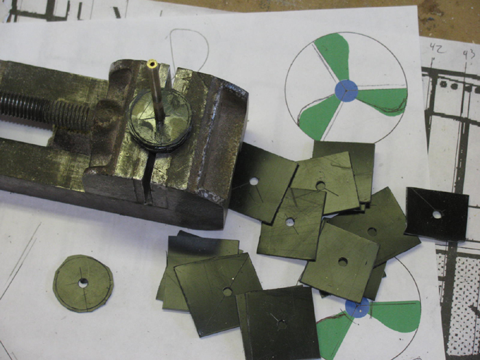
Mark and cut frame squares.
I make them about 1/2" in diameter bigger than needed.
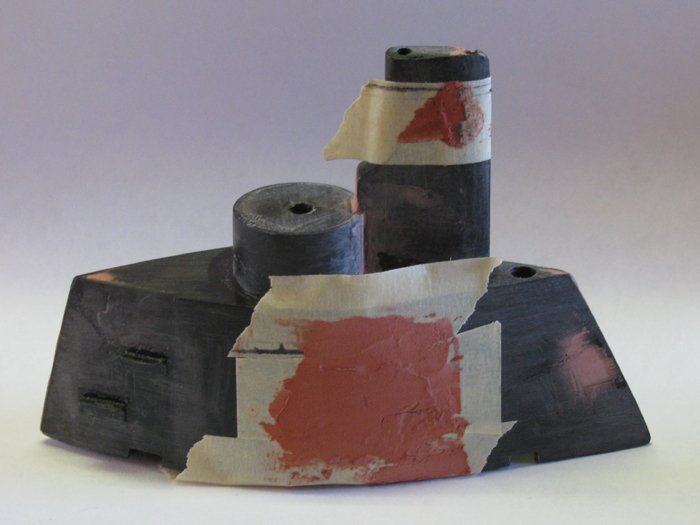
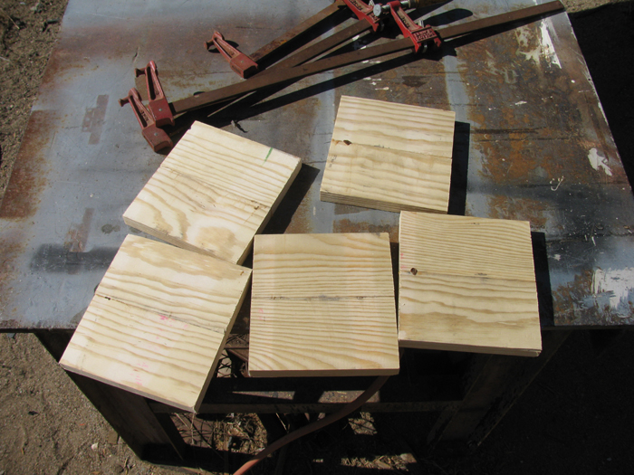
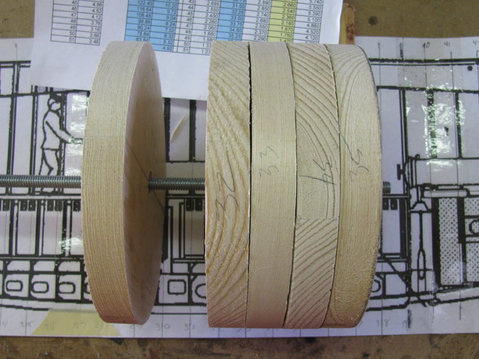
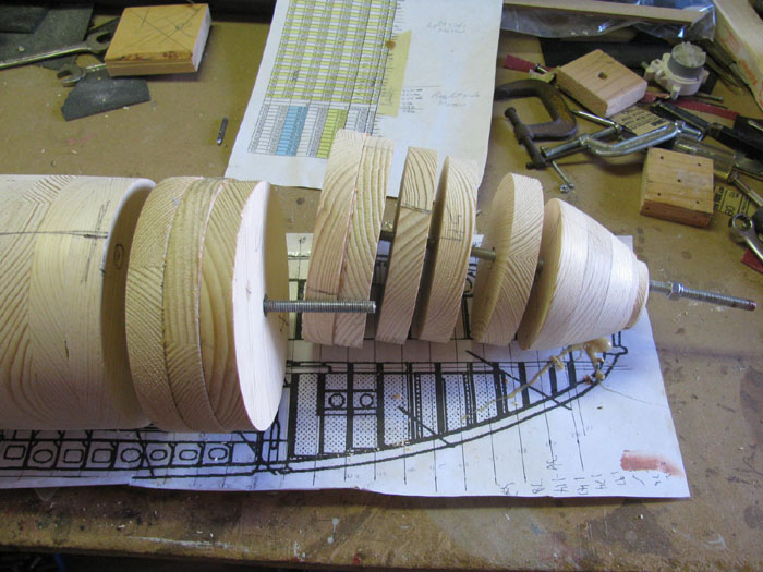
Next photos shows 5 disk blanks in clamps after gluing.
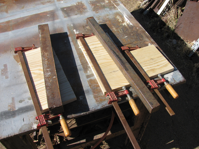
Clamps removed and blanks knocked loose from table.
The table is plate steel.
I put the pieces being glued of areas that I have been paint on.
The glue bonds to the paint or primer and comes loose easily.
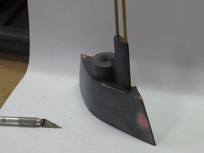
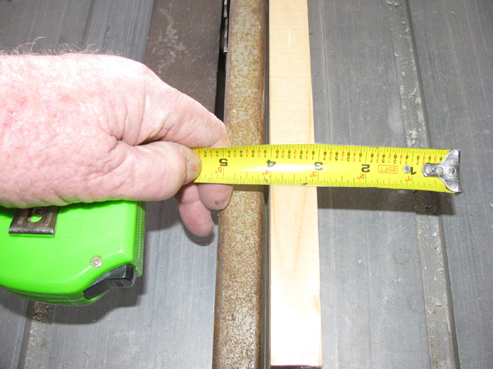
These are made from 3.5" lumber.
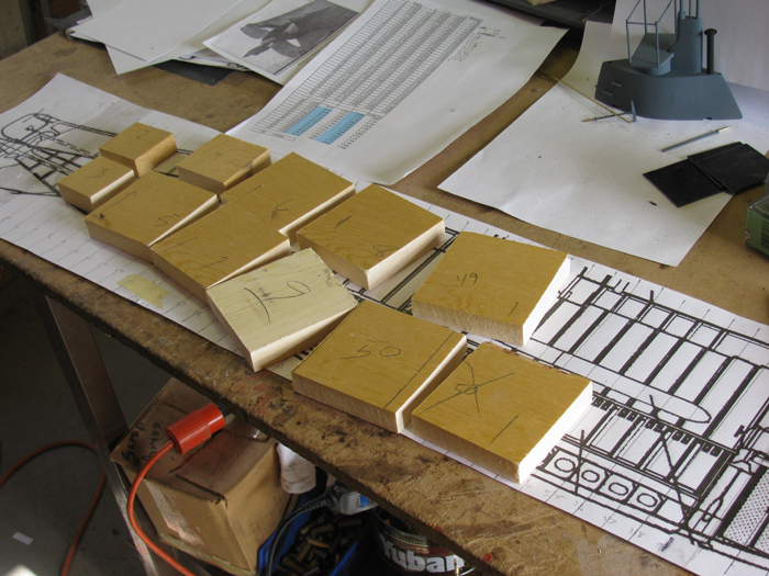
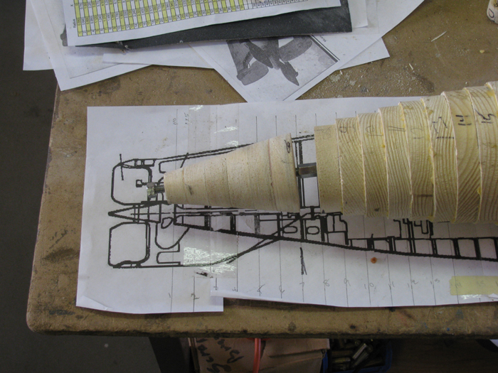
In this photo you can see my spread sheet and my full size profile image
with frame stations marked.
3/4" wood requires frame stations at 3/4" spacing.
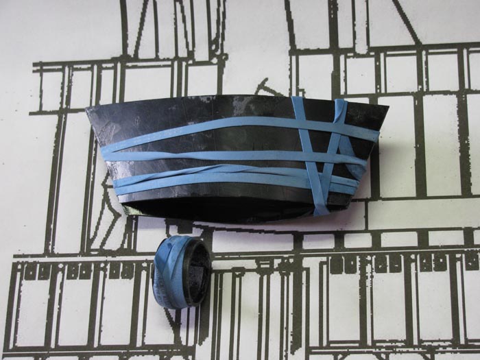
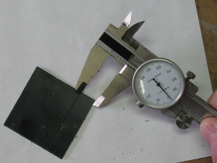
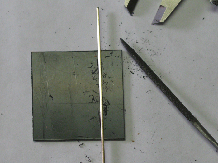
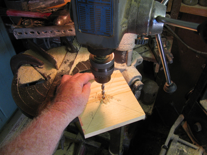
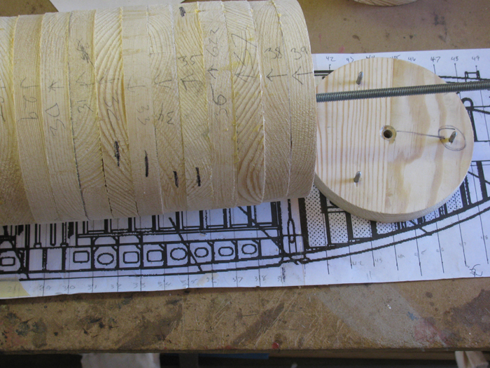
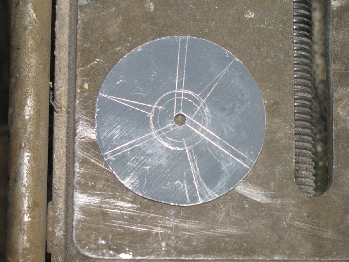
These are small disk blanks . 3.5"-
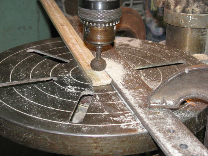
I put pencils mark from corner to corner through the center.
This gives me a center to drill the hole for the spindle.
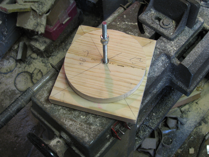
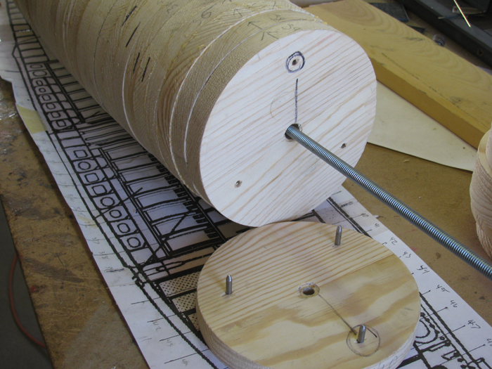
After I drill the hole, I put the square on the spindle and then I stack
a disk that has already been sized.
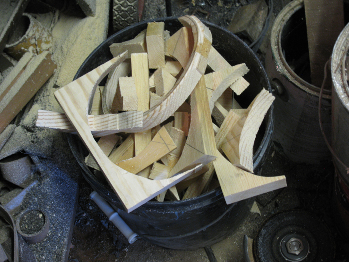
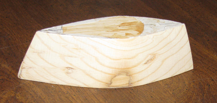
I trace the circle to give me a guide line to trim the square down
to with in 1/4" of the finish line.
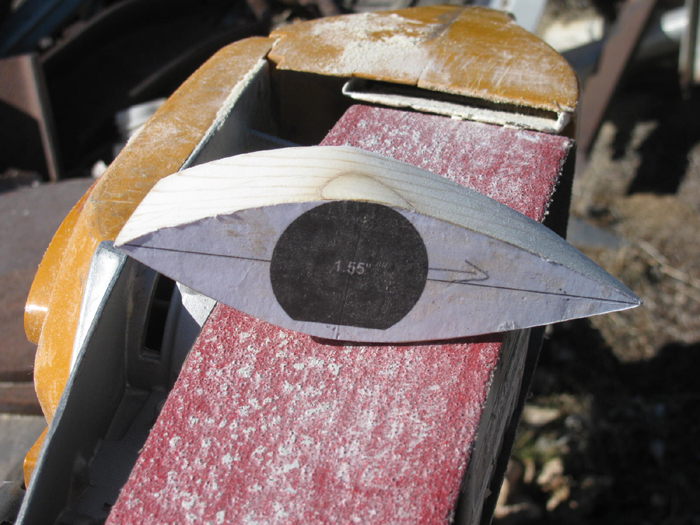
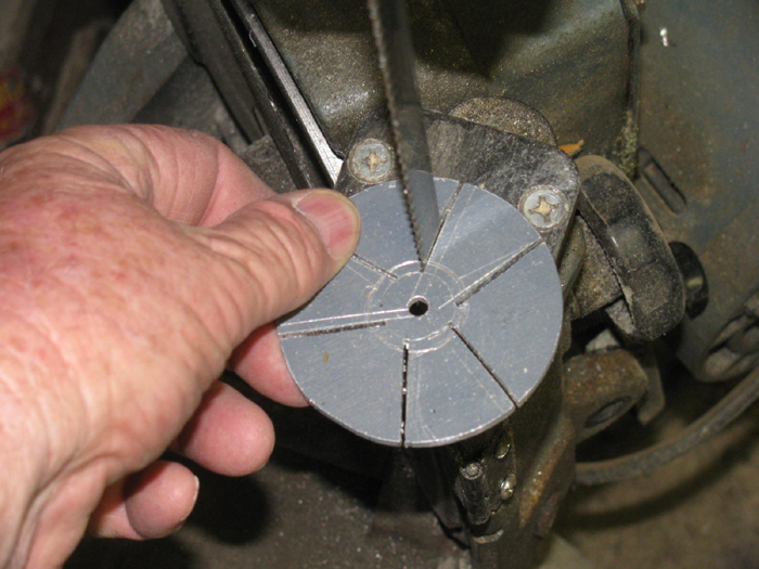
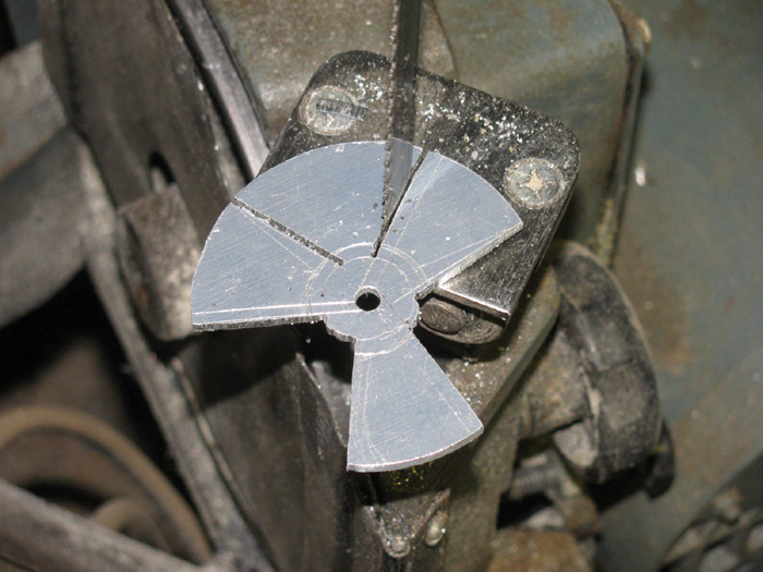
Cutting on band saw.
The line is from the next biggest frame disk.
Trimming the squares in to circles sure fills up a trash bucket quickly.
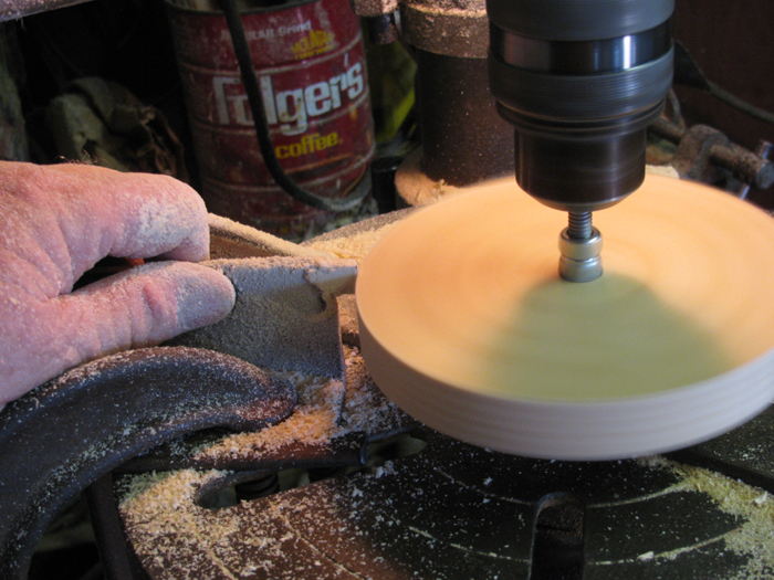
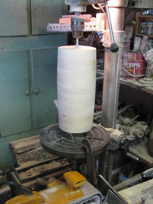
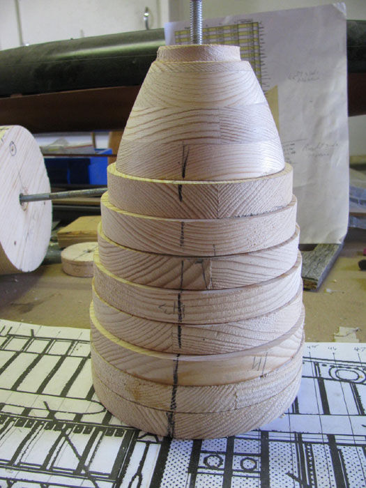
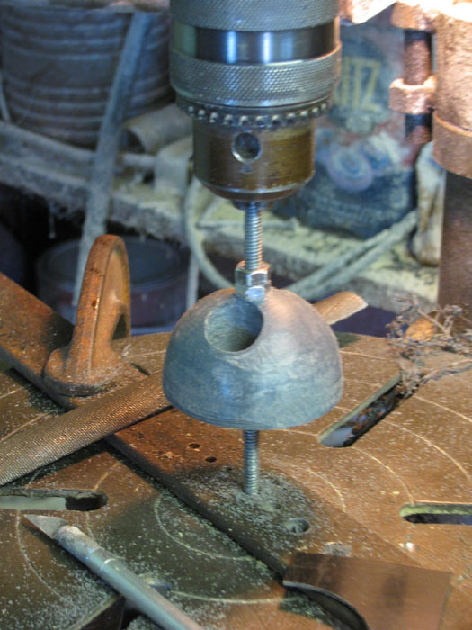
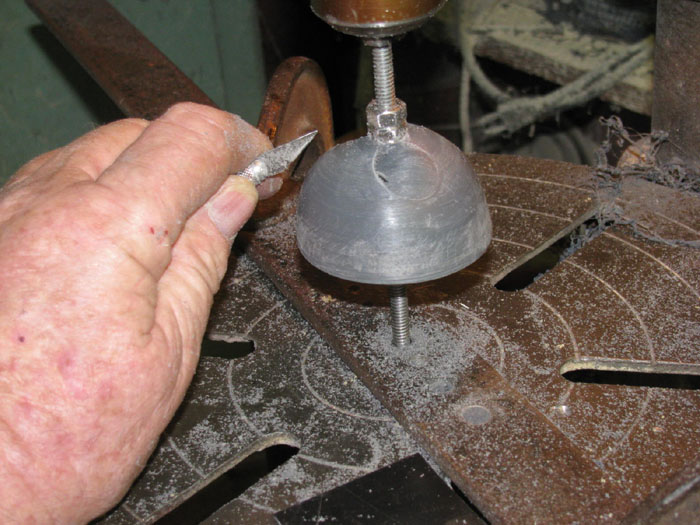
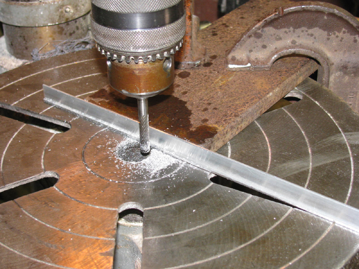
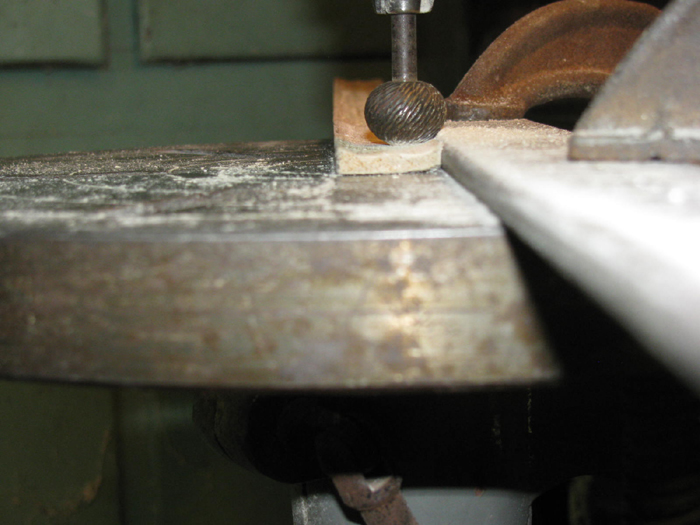
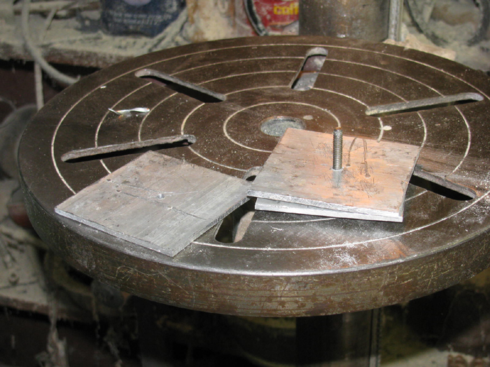
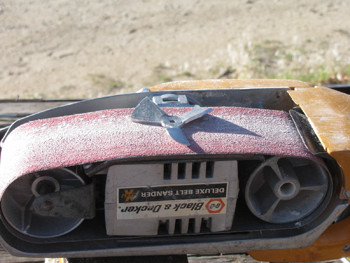
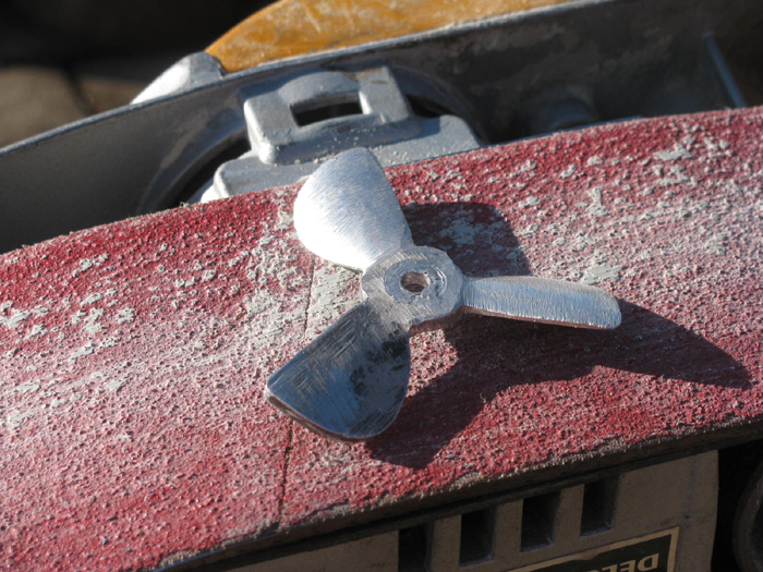
Next step is to chuck up a disk and spin it and cut to finish diameter.
The cutter is clamped to the drill press table.
I am holding the cutter to keep the vibration down.
To adjust the cutter to cut more, I have a 24 ounce ball peen hammer
that I use to tap the cutter without loosening the clamp.
The more I tap the cutter in, the tighter the clamp gets and the smaller
the movement is per tap.
I can adjust .001" at a time as I get to final cut.
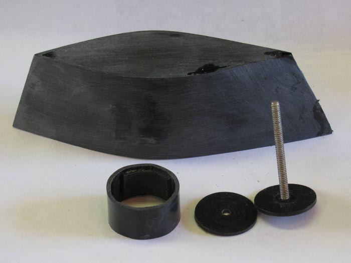
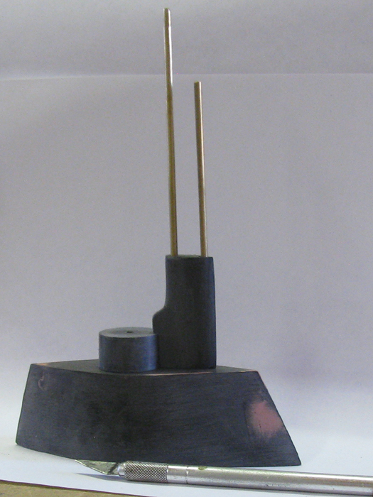
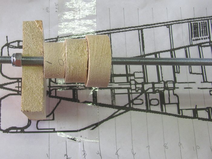
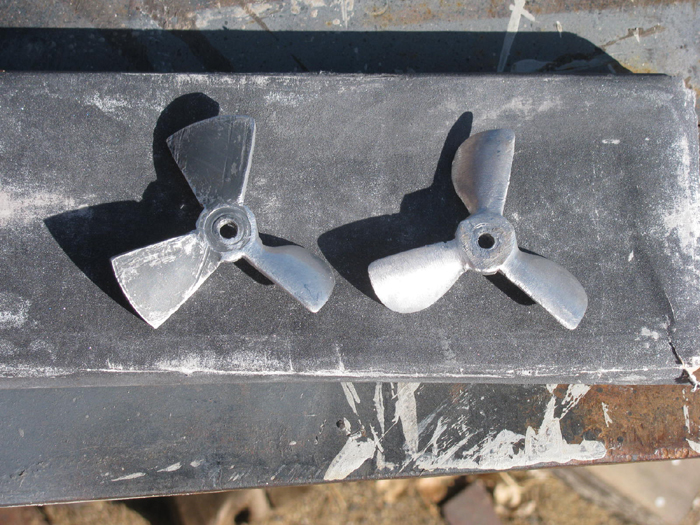
These three disk where made from scrap pieces laying around.
They are on the full length spindle over the full size drawing printout.
I have start gluing two blocks together to make square big enough for
the frame.
I will work on making the disks while I have more blocks in the clamps.
Most I can do is 5 at a time.
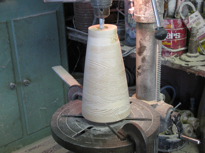
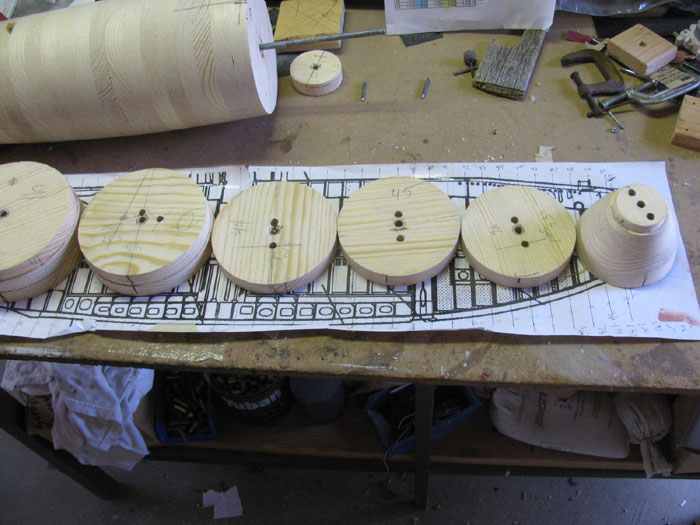
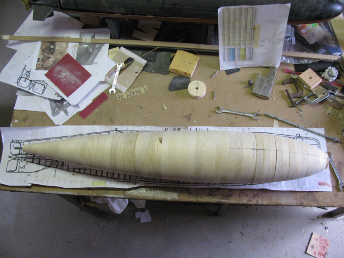
I thought I would start at the widest part of the hull.
There's a reason that will be explained below.
3 frame station have the maximum beam. 33,34 & 35.
30 & 31 have not been made yet.
29 was cut to a smaller size after finding that when I was cutting
frame 33, I had cut too much.
This is why I decided to start with the large disks in case
I made the cut too deep.
I can always go smaller to another frame station and not scrap the
disk.
Above you will notice the dark mark at frame station 39.
The hull is symmetrical about the center line from the stern to the
front of frame station 38/39.
Station 39 forward in not symmetrical and will be hand shaped. (just
about 8" in length, Not too bad)
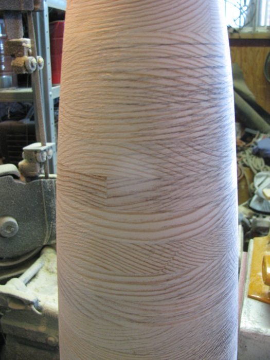
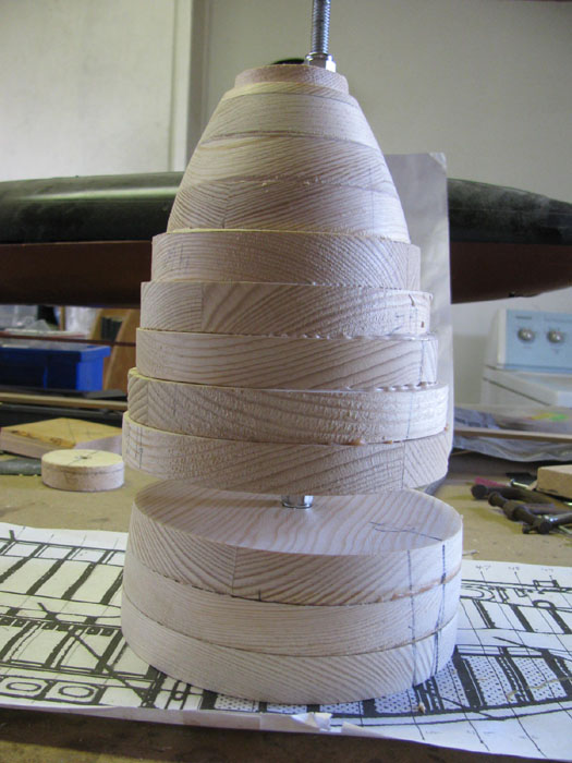
And an overall view of the spindle set over the full size drawing..
A few more disks turned.
What you are looking at is the rear section of the hull that is symmetrical.
Frame 1 through Frame 39 are on a common centerline.
In this photo, I am now working right to left.
Next Frames are 25 to 20.
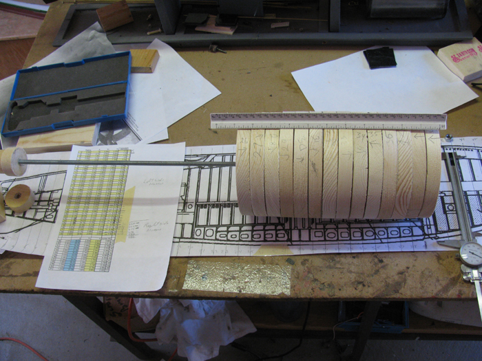
Made 7 more disks.
Only had 2 large blanks glued together.
Had 5 small blanks.
Double checking the finish disk sizes, I found that disk 3 was too
small and had to remake it.
Cut up some more lumber to make big blanks.
There sitting on the outside steel work table glued and clamped.
Will be ready for tomorrow.
Filled in a few more.
More disks done.
Did a count and I need 4 disks for the stern section and 6 disks plus
an over run disk for the bow.
The over run is 1 disk past the final disk for the sanding board to
ride on without going to far on the final disk.
I have already made the stern over run disk.
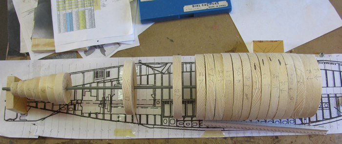
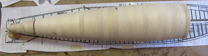
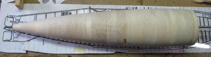
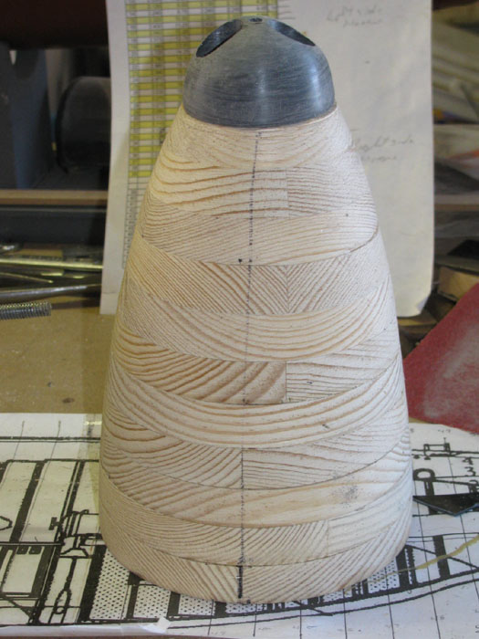
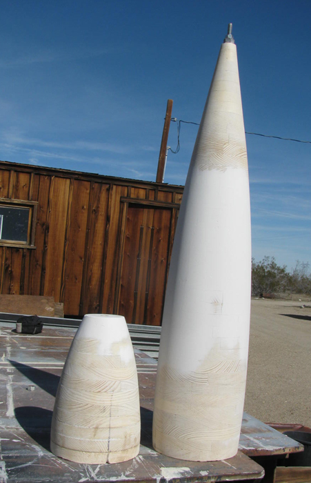
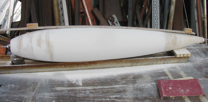
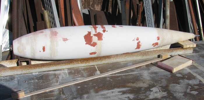
All the frame sections are turned.
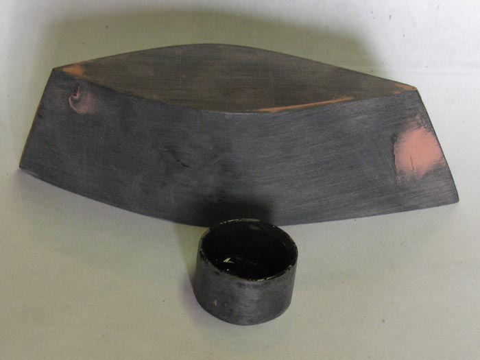
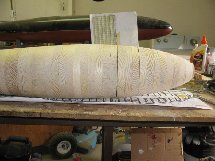
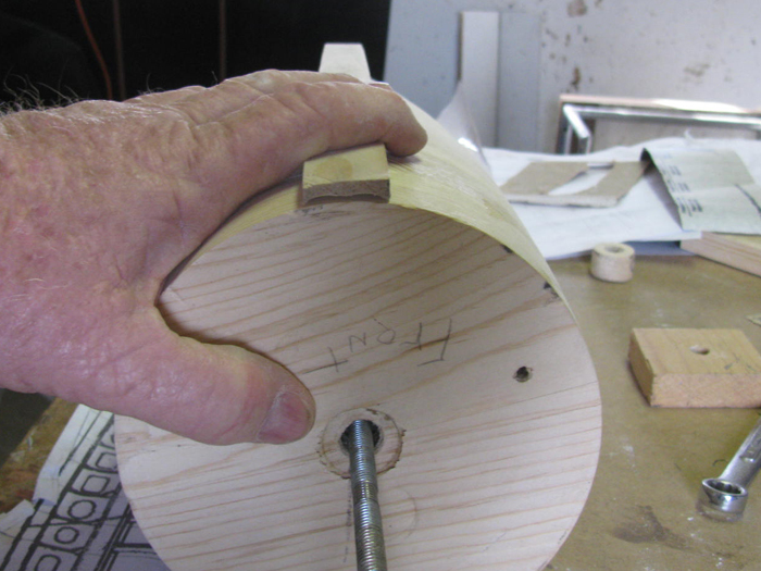
The stern and the bow pieces.
I stacked the bow to show the bow rise curve.
I didn't measure anything,
I just looked at the drawing and set them for the photo.
The top disk is long.
There is a pencil line where it will be cut ... after the sections
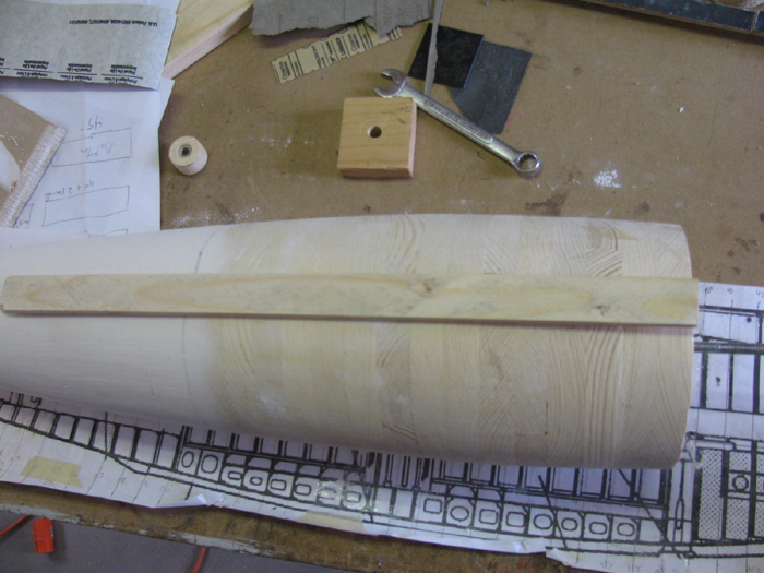
are sanded flat and glued together.
Between some of the sections you can see the disks are not flat and
there is a small gap that needs to be fix by sanding each disk face flat.
Update Photos
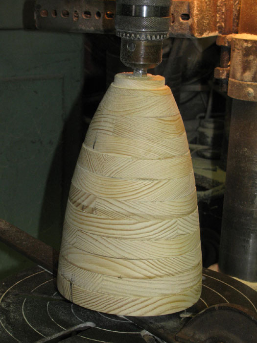
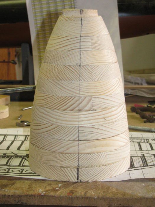
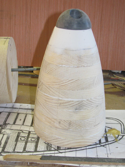
I have rough turned the tail to see what I was getting in to.
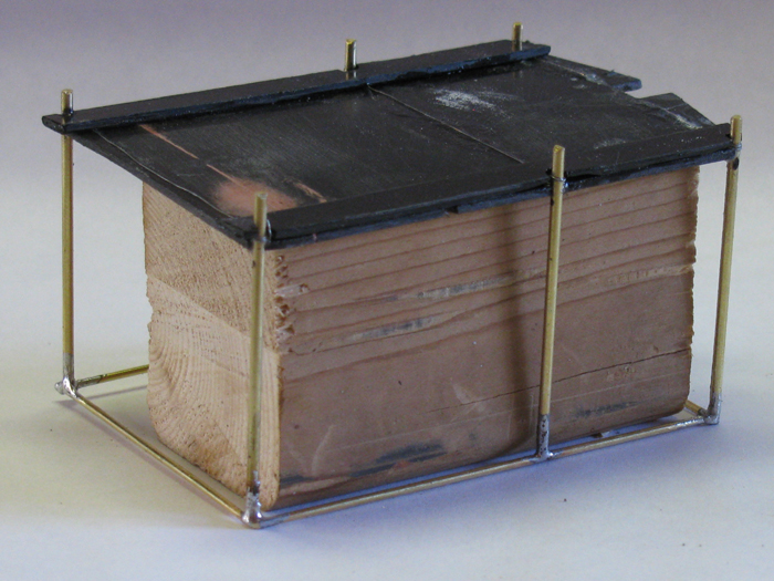
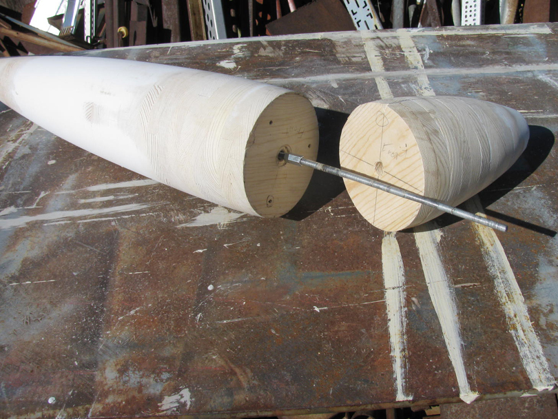
The disk frame sections are glued in four sections.
This may change.
The sections were suppose to slip on to the all thread rod.
But a mistake on my part, glue spread more than expected bonding to
the threaded rod in the back section.
Disk 8 through 20 are permanently glued to the rod.
I relieved the wood disk on the forward end so a connector nut could
be installed below flush with the disk.
The back end the nut can be seen in the photo.
I will drill a larger hole in the tail section to allow the connector
nut to be pulled completely inside the tail section disks.
You can also see a couple of guide pins so the disks can only be put
together one way.

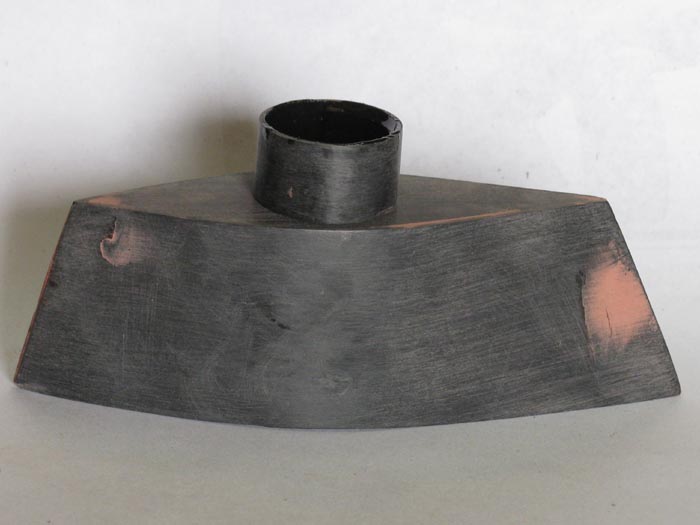
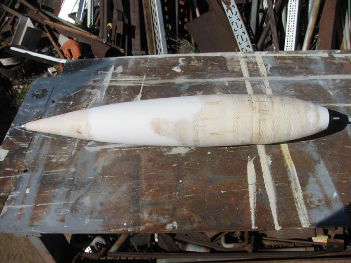
The is the forward section of the main hull.
The rear disk of the bow section is laying down showing the guide pins
and line up mark.
I did drill the holes for the guide pins so they will only fit one
way.
Another view of the forward section hull and read bow section pins.
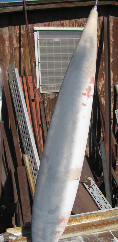
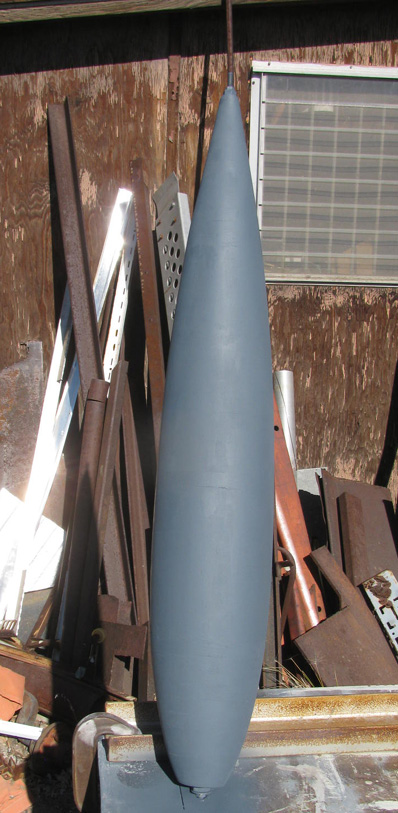
Shaping the hull sections.........
I rough shaped the tail section.
Now on to the front section of the main hull.
I chose to start here because the section has very small steps between
frame disks.
This would be disk frame 21 through 39.
Chucked it up in the drill press.
Slowly worked on it with the belt sander while the section was spinning.
Each frame disk has a high side and a low side when next to the adjacent
disk.
All I have to do is sand the high side down to the next disk side.
This section steps between disk was no more than 1/8", so this went
very quickly.
Rough sanded with belt sander and then hand sanded with wooden block
and sand paper.
I think it came out very nice and on the marks.
Things went so well and quickly, I decided to work on the rear section.
Frames 8 through 20.
This was a little more work because the steps where bigger.
You can see the steps in a photo a previous.
I did not shape the rear most frame disk.
I will do this when I mate up the tail section.
This section is the one that the All Thread is permanent in.
Using the long connector nuts worked.
In this photo there are short pieces of All Thread in each end so I
can chuck it up and have a piece through the table top flat bar guide.
To make sure the front hull section meets up correctly with the bow
section, there are two frame 39 disks.
A & B.
They have the same diameter to allow for shaping together.
Next I need to assemble the tail, rear main hull and front main hull
sections on a single spindle.
Then I can finish shaping all the parts together with a sanding block.
At least that's the plan at this point.
------------------
I have ran in to a problem.
My drill press chuck to table is 3" too short to turn the assembled
back section.
Good thing I built it in sections that can be taken apart.
I had to remove the tail section to get in the drill press.
Right now I am about finished shaping the middle and front section of
the rear main hull.
Disk frames 8 through 39.
I had to remove the tail section to get in the drill press.
I am using the pencil marking while spinning to find the high spots.
I have it down to a 3" wide by 8" tall that appears to be about 1/32"
out of round.
Not sure how close I can get it but I will work on it a little more
before I call it good for me.
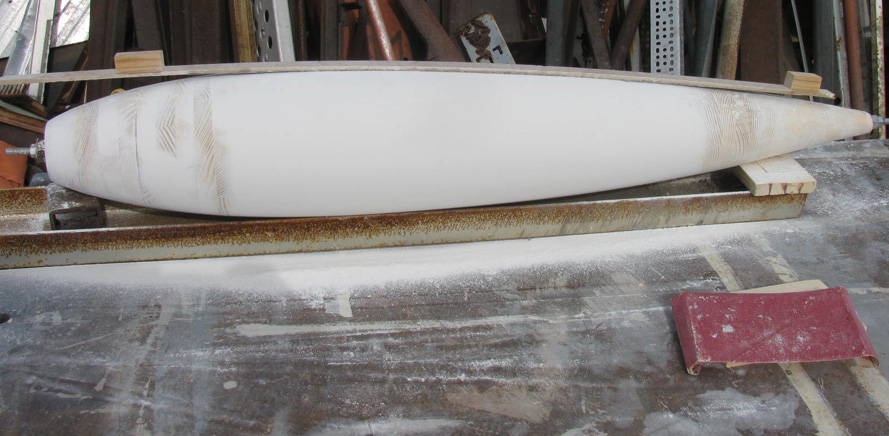
Middle and front sections completed.
Sitting on drawing to check for hull curve match.
The tail section has not been shaped yet.
It is just slipped on to the spindle rod.
The gap is the jam nuts on the rod holding the middle and front together.
I have marked the sections for alignment and disassembled the middle
front the front. section.
I have put the tail section and the middle sections on the all thread
rod.
I did test fitting and decided it was time to glue the two sections
together.
I removed the tail section from the all thread and put some glue
on the front end disk.
Slipped it back on the all thread rod and tightened up the nuts.
Will let is cure until tomorrow morning.
Shouldn't take but 5 to 10 minutes to finish it up.
10 minutes is what it took.
I do have to fill a 3" section that is low.
Not quite 1/16"
Between frame 5 to 11.
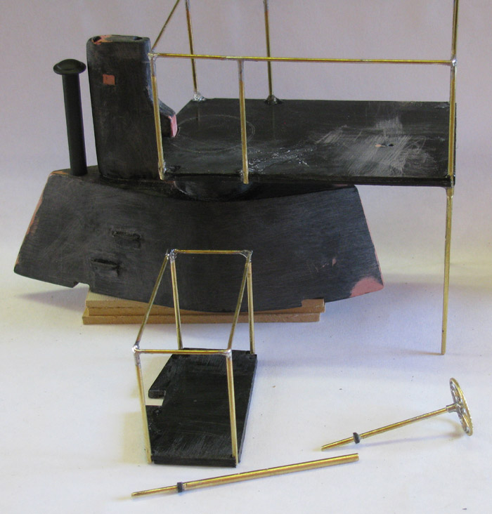
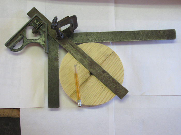
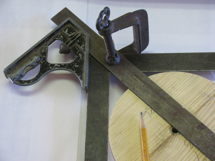
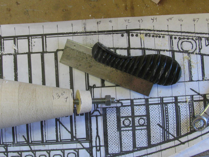
Drawing center lines on round disks
A steel square, an adjustable square and a small clamp.
And a pencil!
Work move inside the house due to the cold.
Measuring and drilling offset holes on bow section disks.
Notice there are two holes off center.
Yep, I measured and then drilled in the wrong place.
Second hole corrected that.
Checking disk section against drawing
The sections dry stacked.
Making sure against the drawing that I have the correct offset.
Once I was good with the offset, the gluing started.
I still did not get the offset where I wanted it.
It is correct for the offset section disks but it does not line up
with the main hull center rod.
I can live with it.
I just won't be able to use the main hull center rod to clamp the bow
section to the main hull when I get there.
The three section disks are glued together.
They are the transition from the main hull to the offset bow.
the three sections are still on the main hull center line and I plan
to use them to help shape the bow section.
Much easier than trying to use the long main hull sections.
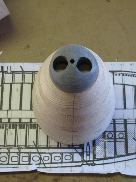
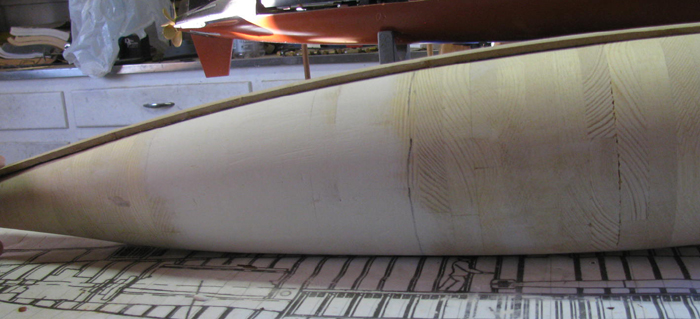
The 4 front bow section disks have been rough shaped at this point.
The bottom three disks are rough shaped but still need a little more
work.
The best part is, the center line of the main hull sections meet the
offset bow sections with the correct hull curves.
My drill press will turn very slowly.
Here is the rough shaping which was done with a belt sander as the
section turned slowly.
I used the lines between each disk to guide how much to remove.
I stop just short of removing the gap line.
The rough shaped bow section set in place on main hull rod.
View of entire hull less bow cap.
Closer look of dry fit.
There is the bow section, the three mid sections and the main hull.
Bow and mid sections glued together.
While waiting on the bow section glue to cure, I thought I would start
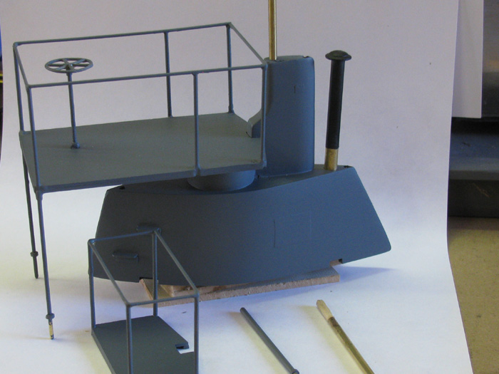
on the bow cap.
This cap rotates to expose the torpedo tubes.
In the photo the cap is rotated showing the tubes.
I measured a cylinder cap mistake (groove too deep) and found I could
make the bow cap out of it.
So, I marked it up for center of disk and I also measured for center
of torpedo tubes.
Drill 1/8" holes them enlarged to the needed 1/4" center and 3/4" torpedo
exits.
Chucked it in the drill press and started in on it.
First, I used a 4.5" grinder to take the disk from 3.5" down to 2.5".
I even took the corner off with the disk grinder.
Using wood turning chisels and then my exacto knife, I rough shaped
the bow cap.
Using my pencil to mark the high spots and then removing material wit
a file, over and over until I got to near finish shape.
I made a plastic template (lower middle) of the shape needed.
Using the template, I removed material as needed.
I now have a rough cut bow cap that is close.
Here it is sitting on the bow section.
Another photo of the bow cap.
============================
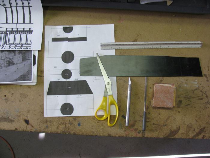
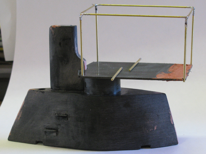
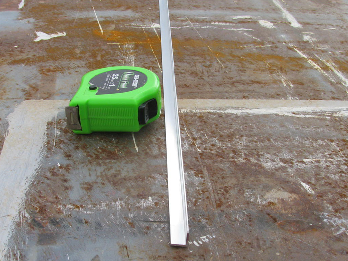
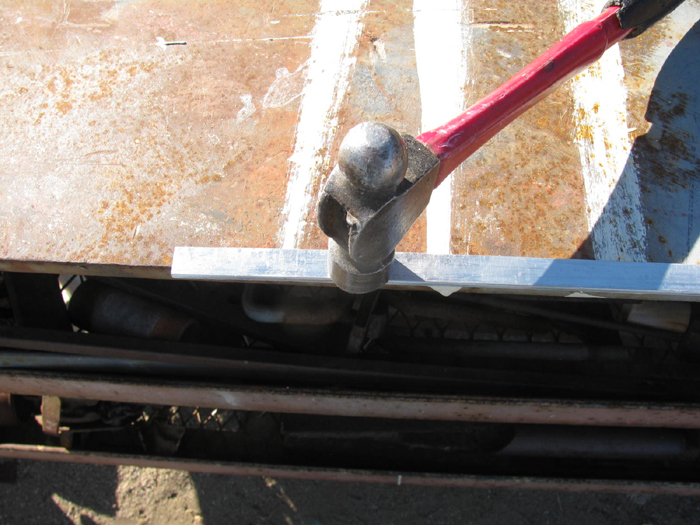
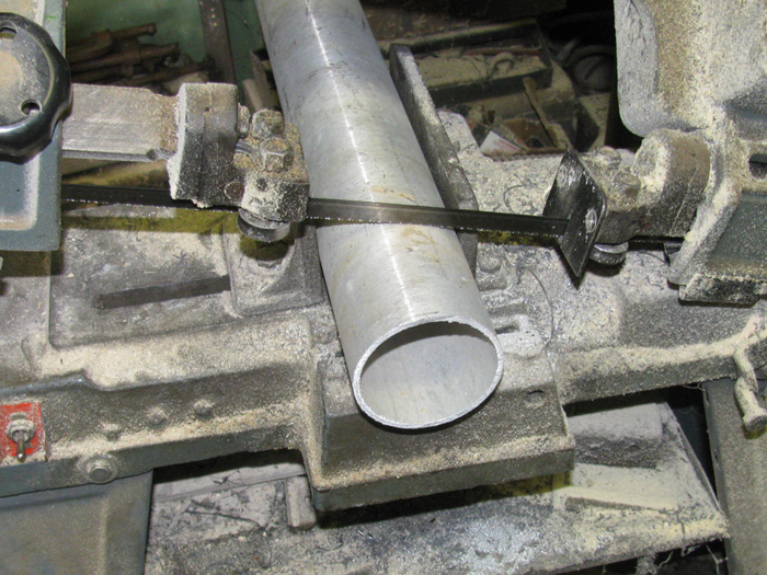
Bilge Keels
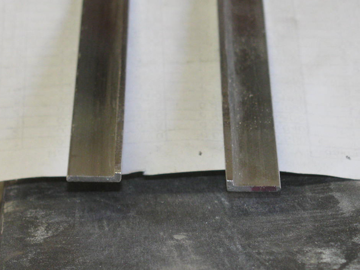
I have the 1/2"x1/2" aluminum angle.
It will be about two weeks before I go in to town again.
So, I thought I would see what I could do with what I have.
Here is the 1/2"x1/2"x72" angle that is 1/16" thick.
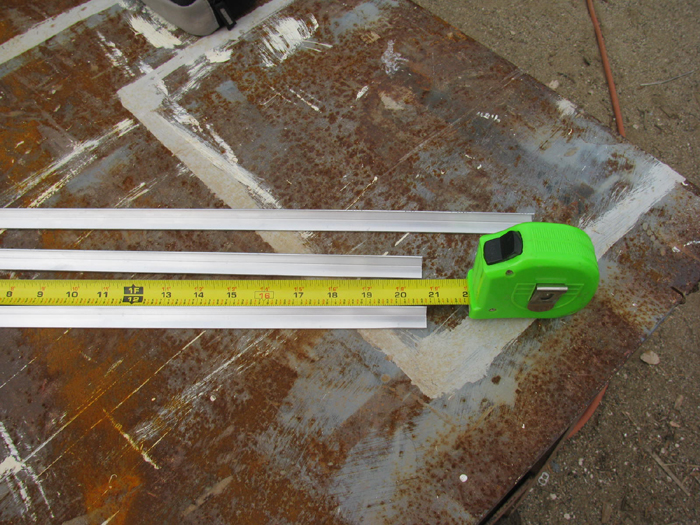
Cut 20.75" lengths.
Finish length will be 22".
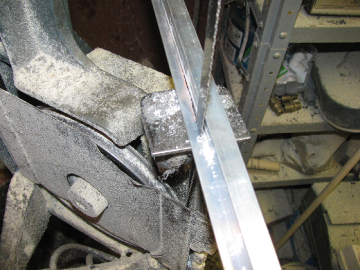
In to the tool shed.
Using my metal band saw, I cut on side off the angle.
I used a piece of the scrap angle on top of the one being cut to give
me a 1/16" safety zone.
As long as it's close, I am good with it.
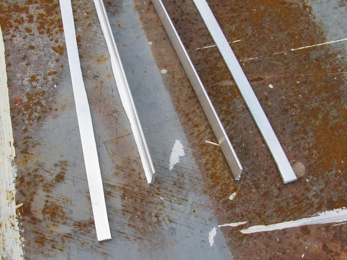
Here are both lengths cut.
Yep straight as an arrow. ;^)
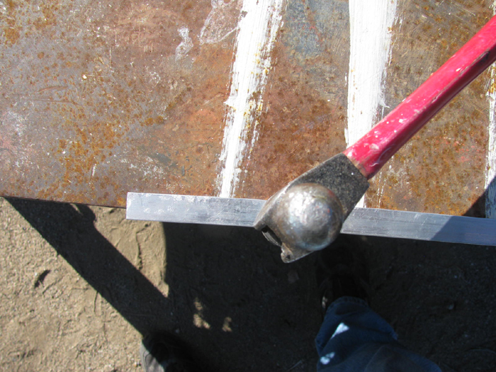
Next, I setup the drill press with a guide plate clamped to the table
and a straight metal grinding bit.
By pushing the angle between the cutter and the guide the rotation
of the cutter will keep the piece tight against the guide.
Works well. Even better when I remembered to wax the cutter.
Next step was to use a block with wet and dry sand paper and smooth
out the edge on the work bench.
I think that is 180 grit. Maybe 120.
The block is 4" wide and 15" long.
It is actually the block I used to sand the joint compound on my bath
room walls.
Here is a look with one bilge keel sitting on the main hull section.
Now to figure out how to mount them.
I think I can drill a small enough hole to pass a thin stainless wire
through and then in to the hull when I get that far.
Time to bend the bilge keel to the profile of the hull drawing.
I need the two keel pieces.
A hammer. (I ended up using only the small 10oz hammer)
A good hard edge that is square. (1/2" thick steel work bench outside/welding
table)
And my drawing as a reference.
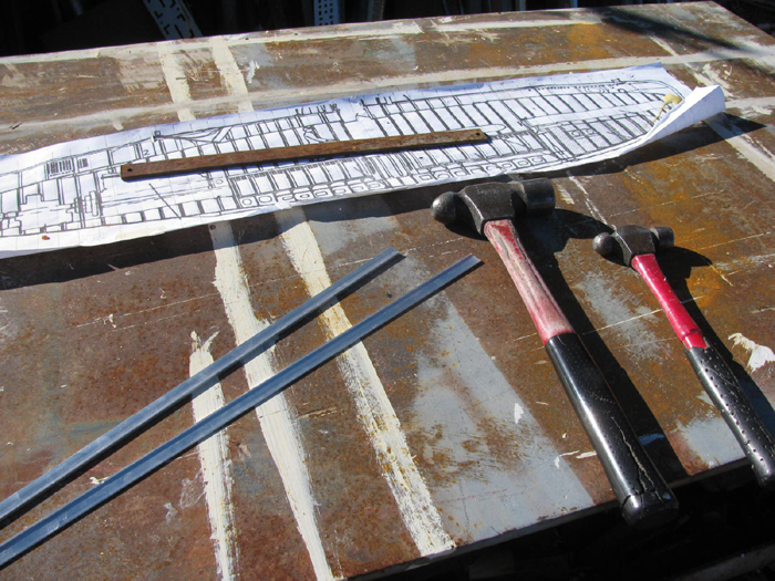
With bilge keel piece on edge of steel table, I took my small hammer
and started tapping.
Not hard but lots of easy hits while moving down the keel piece.
It did not take much.
You can see the keel curving as I move along the piece.
It took me about 15 minutes to shape both pieces.
The one on the drawing has had the warp bend taken out.
Did that by hand and eye.
The bottom keel piece still has the warp in it.
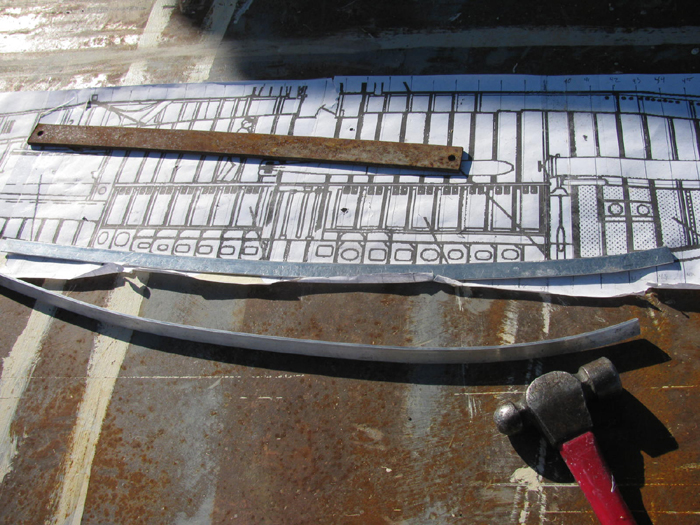
Here are both pieces with the warp taken out.
I will probably need to do a little bit more shaping once I have the
hull shaping completed and can set the bilge keels on their line.
Not bad for 15 to 20 minutes of hammer tapping and hand bending.

Main hull section with bendy sanding board sitting on top.
Bendy sanding board pulled down against hull to smooth glazing to profile.
By keeping pressure on the bendy board at each end past the glaze keeps
the bendy board curved at the correct profile while sanding.
I can move the bendy board side to side or around the center axis and
keep the profile right.
Bow section with bow cap sitting in place.
More glazing to do before it is correct.
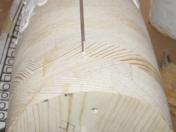
The Keel
I started with a true 1" thick board.
I need 15/16" finish width.
I made a 1/4" wide strip.
Cut a 15", 11" and a scrape piece from the strip.
To set the keel strip on the hull, I needed to concave one side.
I clamped a metal stop guide and chucked up a ball grinder bit.
By pushing the wood, left to right the rotation of the bit keeps the
wood tight against the guide.
I set the bit to take very little at a time and made several passes.
Did one side then the other.
When I got down to the depth I wanted, I knocked the guide closer to
the bit to cut closer to the edge.
Kept doing this until the cut was right at the edge of the wood without
cutting in to the sides.
Removing material from the center allows the wood to sit down on the
curved hull at it's edges.
Here, I have the back section of the keel sitting on the hull.
The keel is very wide. Almost 24" in width and (guessing) about 9"
thick.
Reference from photo.
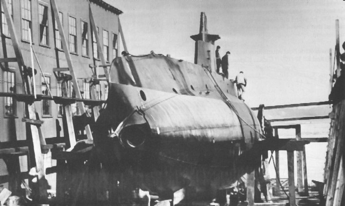
Now here is the issue.
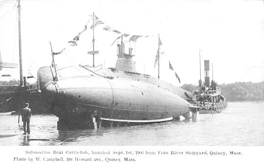
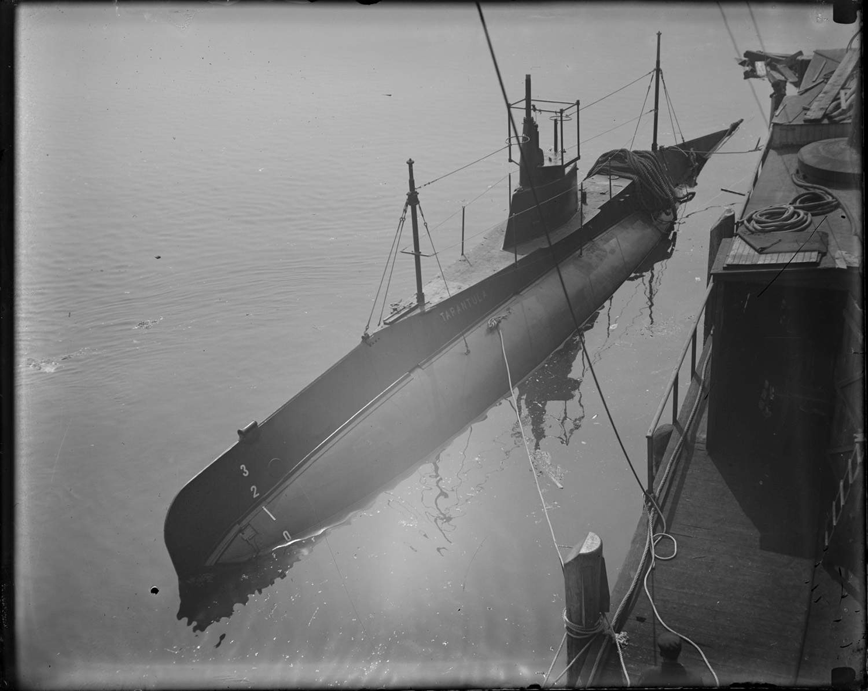
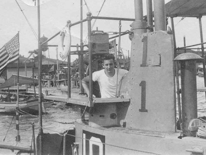
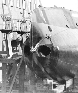
This is not a photo of a B-boat but instead a C-boat.
Over the last 20 years, I have not found a clean/clear bow photo of
a B-boat showing the bow cap and keel.
So, I am going with this photo.
Today, I did a few little things.
I sanded down the second coat of glaze on the main hull sections.
I cut the tail cone to get to the correct hull diameter.
I had run the tail cone long to allow better belt sander run out.
I also finish spinning the frame disk to size that goes between the
bow section and the main hull section.
I glued it to the bow section and it is sitting with center bolt tightened
and a couple of long wood clamps.
This is a big event.
Next, I will glue the bow section to the main hull section and align
it all.
Will not happen tomorrow.
May happen on Friday.
Once the glue cures, I will have a full hull less the bow cap which
is separate any way.
I can continue with the glazing until I get a smooth hull curve over
the full length.
=====================
Today's update
Sanded the glazed hull with the bendy board.
Applied another coat of glaze.
Getting close to being done.
Sanded the taper to the sides of the bilge keels.
Made the back end tip.
While I had the belt sander in the vise, I took on the wooden conning
tower.
I made the block several months ago but never shaped it.
I had printed out a top and bottom pattern and glued them to the top
and bottom of the block.
This is looking at the bottom pattern.
Shaping is done free hand making sure not to sand past the lines.
This leaves some for hand block sanding should it be needed.
This is the rough shaped conning tower.
You can see the top paper pattern on it.
Still glazing the main hull and bow section.
This was this morning after sanding.
There are lots of little bubble holes and hollows.
Since I took this photo, I have glazed the holes and hollows again.
Getting close to where glaze will no longer do the job and I will have
to use primer and sanding to fill the blemishes out.
I am thinking that after tomorrow's sanding, I will be able to
permanently join the bow section to the main hull section.
Then the glazing starts over.
Dry fitting tells me that I only need to glaze 2 frame disks on the
bow and 2 frame disks on the hull section.
4 disks in width to fair the hull line in.
The line on the bow section is the top center line.
There is also a notch I cut in to the hull so I don't loose the top
center after glazing and priming.
Joining the main hull section to the bow section.
Connector nut and all thread rod.
Drilled 5/8" hole in the rear of the bow section so the connector nut
can be buried inside the bow.
Glue applied.
Bow section slipped on the all thread.
Nuts and washer put on rod and tightened.
While tightening, I used a hammer to keep the two section aligned.
I have not started the glazing where the 2 sections are joined.
Been working on other parts.
It has been some time since I updated this project.
Work has been done but life got in the way several times, including
a complete rebuilt of the top end of my truck engine.
The plug has been filled and sanded so many times I have lost count.
This morning, the weather cooperated with cool temperatures, no wind
and high clouds keeping the direct sun off.
The no wind was an issue as the dust from sanding wouldn't blow away.
Here is the hull sitting on a piece of 4" channel to keep it steady
while sanding.
In front of the hull is a sanding block with 100 grit sand paper on
it. (red)
And the is my 3/4" wide bendy board with 180 sand paper glued to it
as well as two handles.
Bendy board sitting on top of hull.
The sanding is done around the hull and not end to end.
There is wood exposed at the tail end and there are certain frames
that are exposed as they are true diameter.
These are used to hold the bendy board while sanding.
I would sand from top center to about 2" away from me.
Pushing the bendy board as I controlled the angle level to the surface
where the bendy board was at the time.
Checking by running my hand over the hull feeling for bumps and irregular
surfaces.
After getting what I wanted, I cleaned off all the dust and did a damp
rag wipe down.
A close inspection found small indents where filler had not been built
up enough.
Filled in these dents and brought indoors to dry.
The best part is I think I like what I have now.
A little more sanding on the filler and then primer.
Once primed, I can use the red glaze to finish ot the surface.
Red Glaze filler applied.
Sanded and the start of priming.
Second coat of primer applied.
I will let it dry a day and then back to sanding.
This will go on until all the little blemishes are gone.
====================================
Today was one of those days.
Before I even opened my eyes, thoughts were running rampant with ideas.
To stop this, I had to go out and see if I could make those thoughts
in to something.
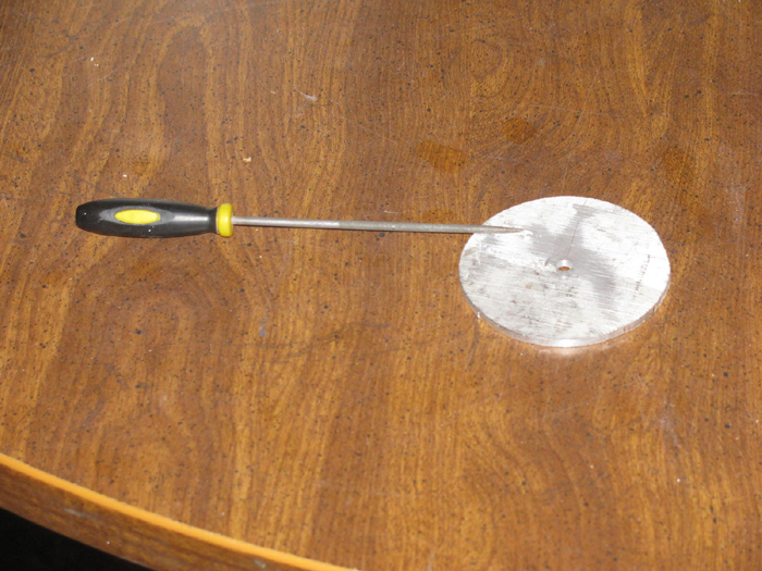
I needs a 2.5" square of aluminum.
Nothing fit the bill.
Took a piece of 3" diameter aluminum tubing I had and cut a piece off
the end.
Knowing what the tubing grade was, I knew I could flatten it out without
it cracking and still have it's strength.
I split the piece of tubing on the band saw and then out to vise I
have outside.
Some hammering.
Some bending with a steel square tube.
Then using the vise jaws, I was able to straighten the piece out.
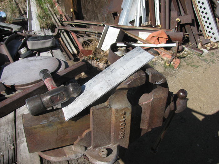
On the steel work table I made the piece as flat as my eye would allow
and I rocked it on the metal table flat surface until it sat completely
flat on the table.
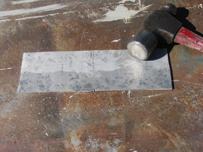
Back to the table saw and I cut the 3 squares.
Marked the square diagonally to get a center for drilling a small hole.
Drill the 3/16" hole.
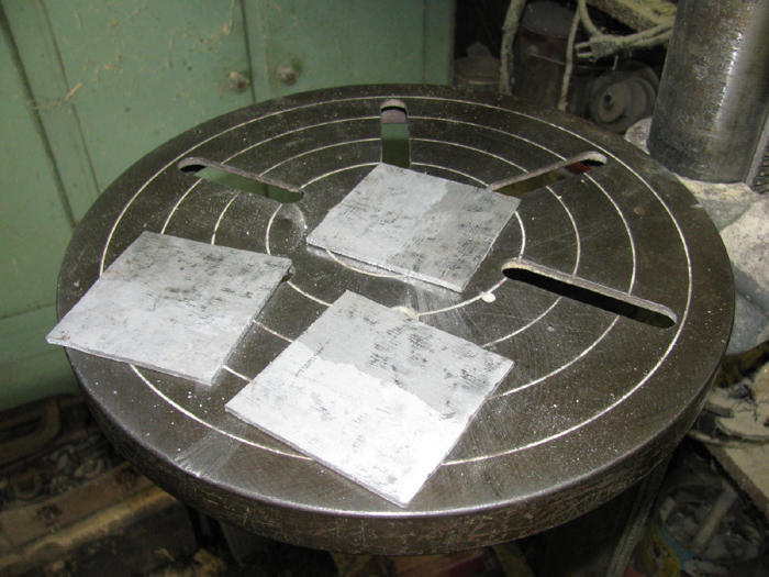
I only need 1 finished item.
Maybe 2.
Found a small bolt and put the three plates together.

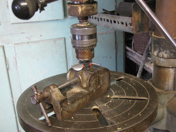
Chucked it all up in the drill press and spun the parts to get them
round at to a diameter of 2.625".
Here is 1 disk on the kitchen table.
Next step is to scribe the lines where I will cut the blades and hub.
Have you figured it out yet?
I looked for a piece of brass 2.5" square about 3/16" thick but no
luck without spending a fortune and then double that for shipping.
So what I was thinking about when I woke up was a way to not need brass
and use something I already had.
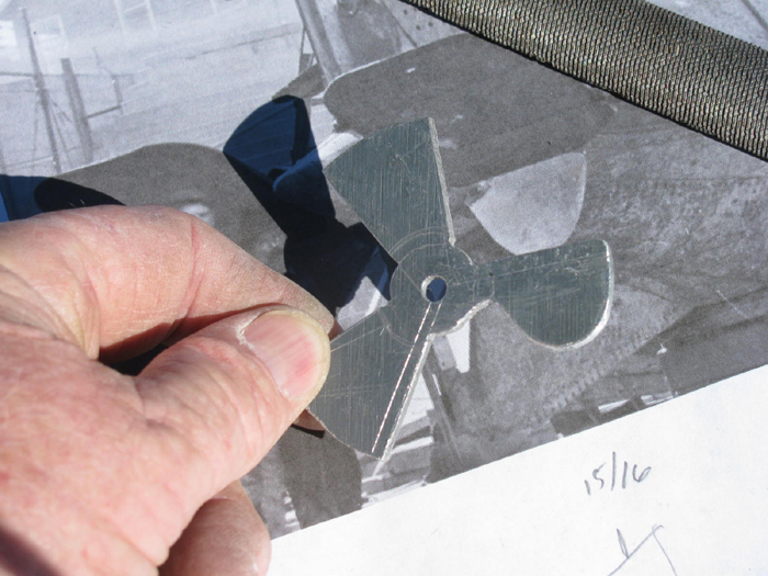
The B-boat has a very large propeller hub.
I think I can sandwich the aluminum plate between some stacked plastic
disks that will be turned before adding the aluminum.
The aluminum will be shaped and then the blades bent for the needed
bit.
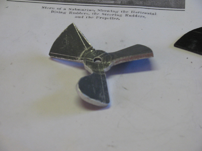
I have been looking to see if I could find one already made but looking
at photos of the B-boat, I learned the the blade is built backwards for
standard ship propellers.
The rounded edge is the trailing edge and not the lead.
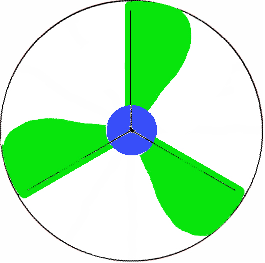
After looking at many propellers, this is a rough drawing I what I
see.
If this was on a ship, it would rotate clock wise.
But on the A and B boats these rotate counter clock wise as viewed
from the rear.
The blue is 5/8" but will actually be 3/4".
The propeller hub at the blade intersection is 1" in diameter.
The blue section should be 3/8" large in diameter.
Overall diameter of propeller is 2 5/8".
When I cut the blades, I will cut one and shape it to finish.
Then I will make a pattern so I can scribe the other two blades.
More to come as I progress on this.
=======================
I primed the disk with dark gray so scribe lines would show up better.
Here is the 3 blade center lines.
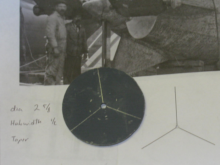
Scribed the leading edge and trailing sedge extreme width.
Also included the hub diameter and the inside line where I want the
propeller center to be.
This is to allow covering the twist in the hub cone.
Cutting the straight limit lines.
Cutting out between the blades.
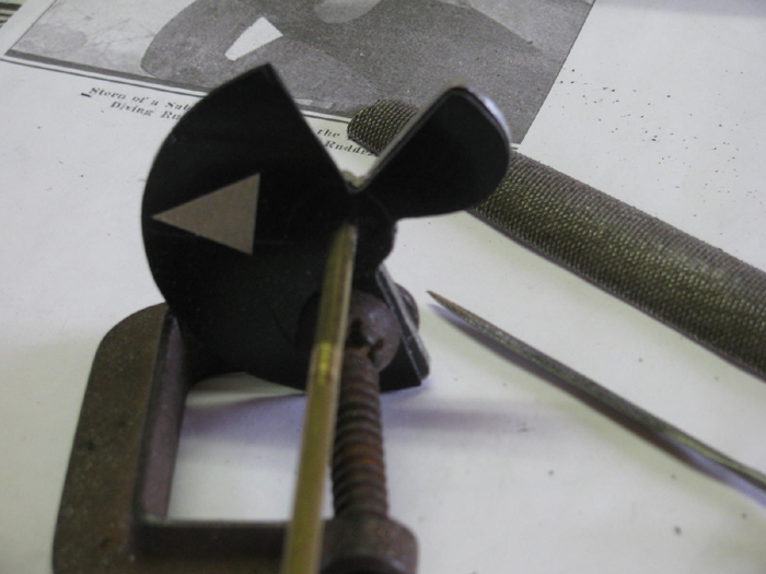
Moved to the large outside vise to start shaping 1 blade with files.
Comparing the shape with the photo.
Getting close.
Not having any real drawings or numbers, I think I will stop here.
I will make a pattern from this 1 blade to scribe the other 2.
The pattern will include the center hole so I can rotate the pattern
in to place.
===================================
The above prop shape did not work for me.
I did more looking and found a couple photo of props under large ocean
liners.
Even photos that were straight on from the back.
So, I scaled 2 of them and choose the one that looked the most like
the B-boat prop.
Of course the ship props are curved to bit rounds side and the B-boat
is curved to bit on the flat side.
But the shape fits.
So, here is my second try.
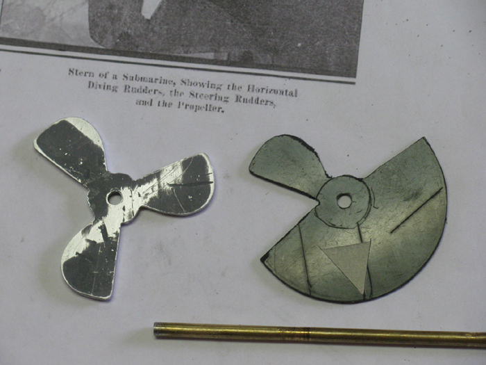
Remember I made 3 aluminum disks.
Primed the disk so I could see the scribe lines.
I made a plastic pattern which does several things.
Center hole.
Blade shape.
And the all important 120 degree off set.
That would be the tape arrow.
Using the front (flat) side of the blade and the arrow gives me the
next flat side location.
I rotated the pattern around the brass shaft and scribed my outside
diameter.
Then I scribed one blade at a time.
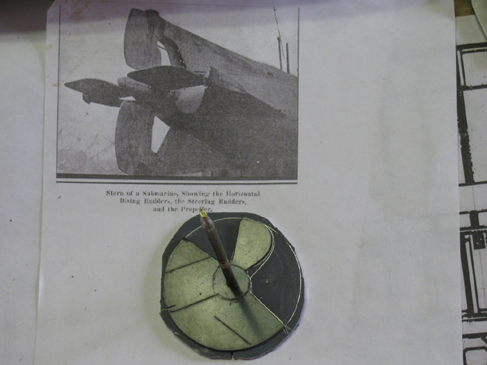
As you can see there was a change after the first scribing.
I needed to reduce the size at the hub.
Why, because the circle scribed is not the hub but my stop cutting
line.
The hub will be 3/16" wider than the stop cut line.
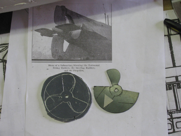
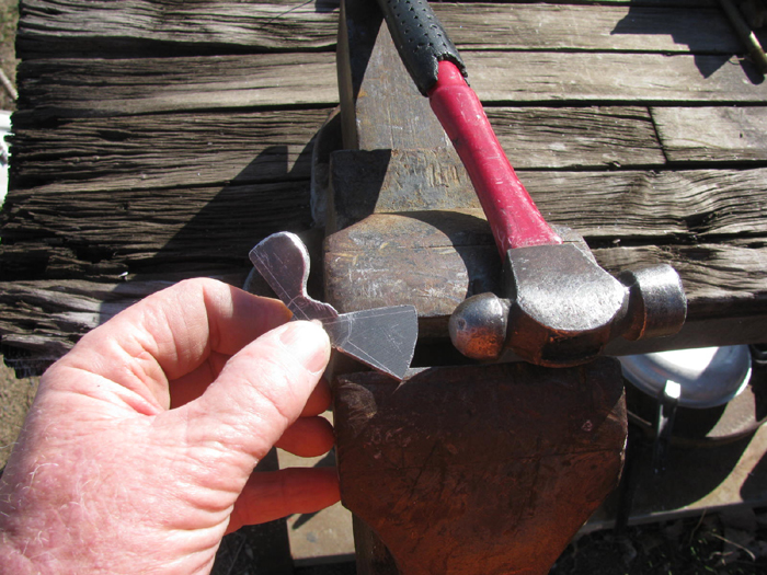
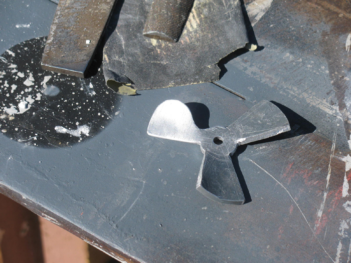
Here is the rough cut prop using the band saw tilted vertically.
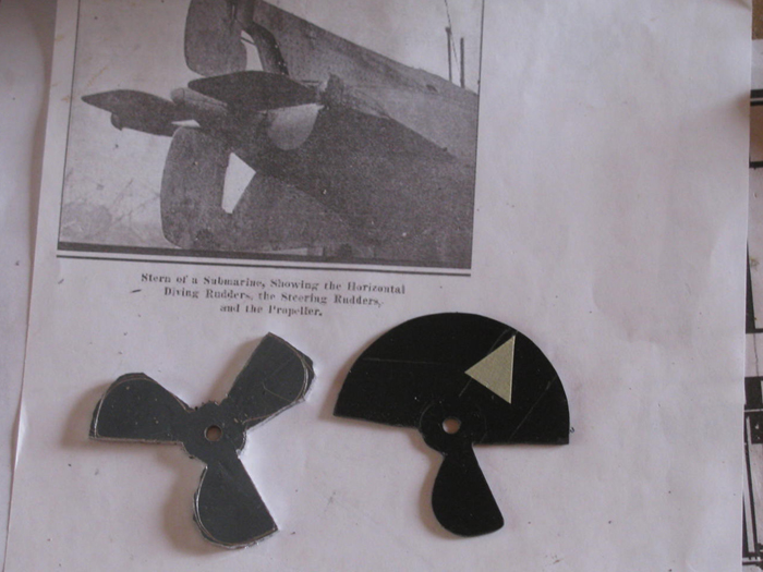
Using the pattern and a couple hand files, I shaped each blast to the
pattern.
Filing complete.
Next, I will make a jig to bend and curve the blades.
Haven't made the jig yet but I thought I would see how hard this was
going to be by shaping the first blade which is incorrect.
In the vise.
Adjustable wrench in hand and not too much effort the blade twisted.
Here all three blades have been twisted.
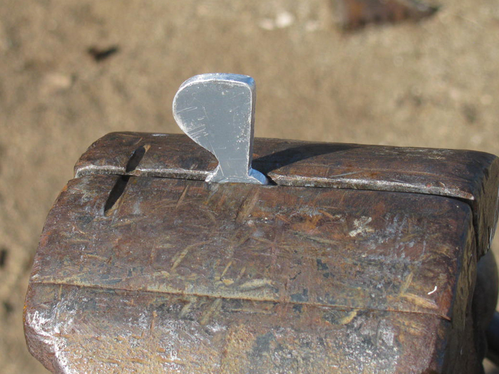
Back out to the vise with my trusty little ball peen hammer.
Opened the vise jaw so it would support the leading and following edge
of the blade.
Lite tapping down on the center of the blade and then closer to the
leading edge.
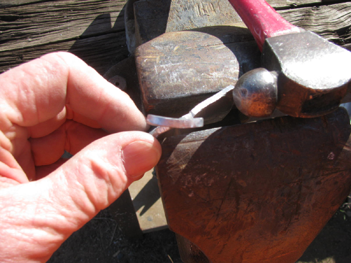
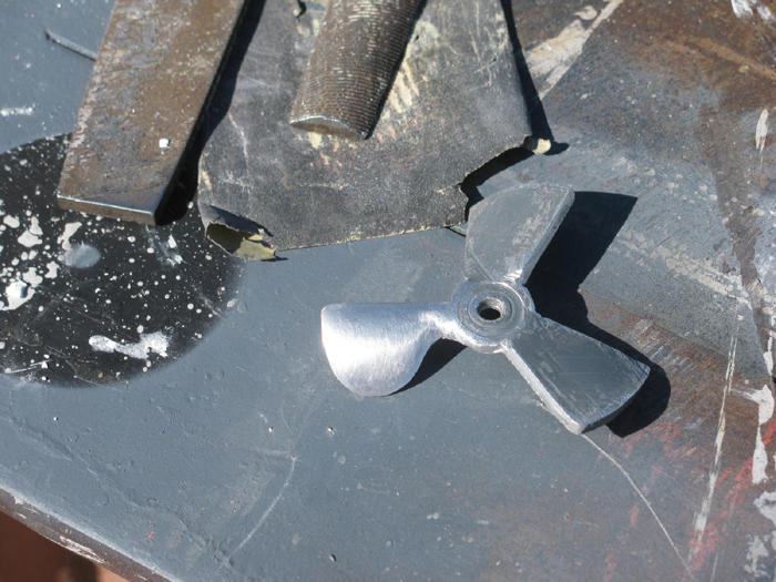
All three blades twisted and curved.
Just needs some shaping with a file to sharpen up the edges.
Won't be doing that to this test blade.
Time to do this was about 15 minutes.
I learned what I wanted to know.
I will make a single blade jig with a center post.
This will help me get all three blades the same shape.
I'll spend some time making the jig out of steel so I can hammer against
it if need be.
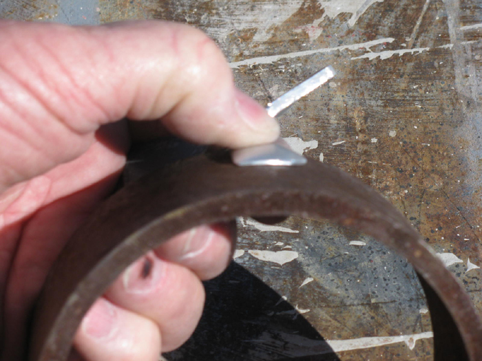
I found a pipe ring in my junk pile that was very close to the blade
curve I want.
Using the pipe and vise I pressured the blades in to the curve of the
pipe.
I am working on the test prop and not the final prop.
Sorry, I didn't get a photo.
I will when I do the final prop.
Here is the face of the blade after filing and sanding.
Here is the back side of the blade after filing and sanding.
How about an edge view?

I did set the blade back on the pipe to see if filing had changes the
shape.
It did not.
Still need to build a jig so I get the blade bend to the hub the same
on all 3 blades.
Jig consisted of using the original test prop and putting the final
prop blades back to back to get the same height.
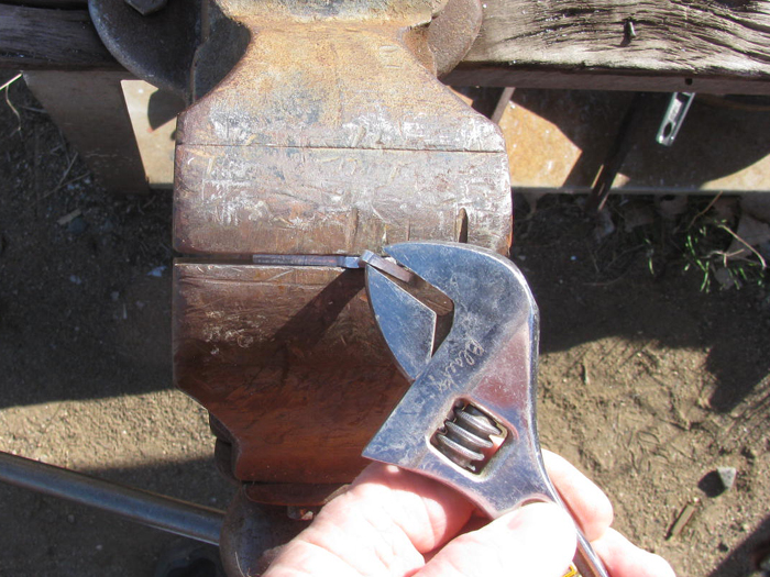
This was after using my vise and hammer to curve each blade.
Hammering slowly the blade past the curve I wanted then using the pipe
to flatten out the over curve.
Did this by placing the pipe piece with prop blade between the vise
jaw and pipe ring and closing.
Once I had it closed tight, I hit the vise jaw with a single hard hit
with my little hammer.
Photo below shows the first blade having been shaped using the belt
sander held in the vise.
One more blade to do.
Original test prop next to final prop.
Some sanding with 120 wet/dry should do it.
======================
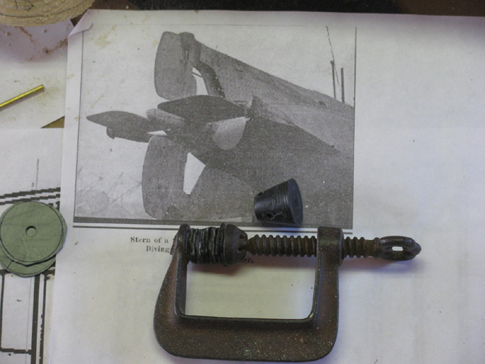
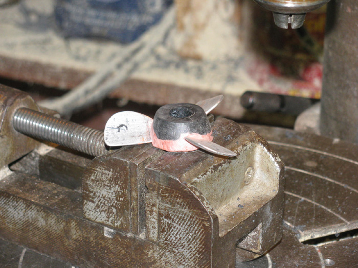
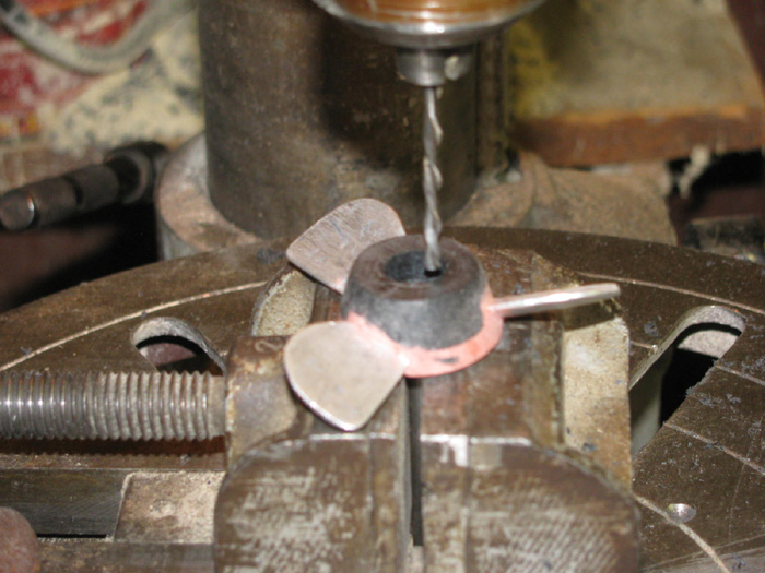
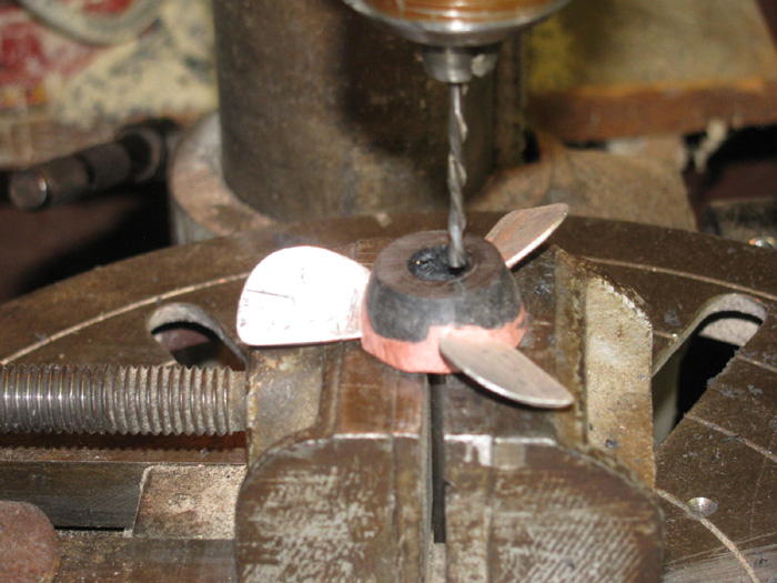
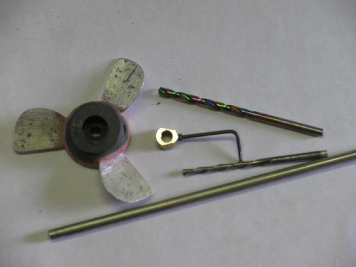
On to building the propeller hub and tail piece that holds bearings
for rudder and rear planes.
Cut a bunch of squares from scrape plastic and drill a 3/16" hole in
the middle
3/16" will be my propeller shaft diameter.
Using my calipers as a scribe, I placed one end in the hole and the
other end I used as a scribe to give me a circle line that was larger than
the finish part.
Using a brass tube as a shaft, I started gluing and stacking needed
sections.
The stack in the little vise and the single circle of plastic will
become the propeller hub.
The squares will become the part behind the propeller.
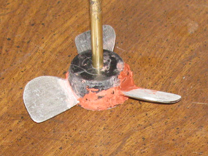
Glue has set up and I have turned the propeller hub parts.
There will be a small piece on the very back once I get the propeller
set in to the hub.
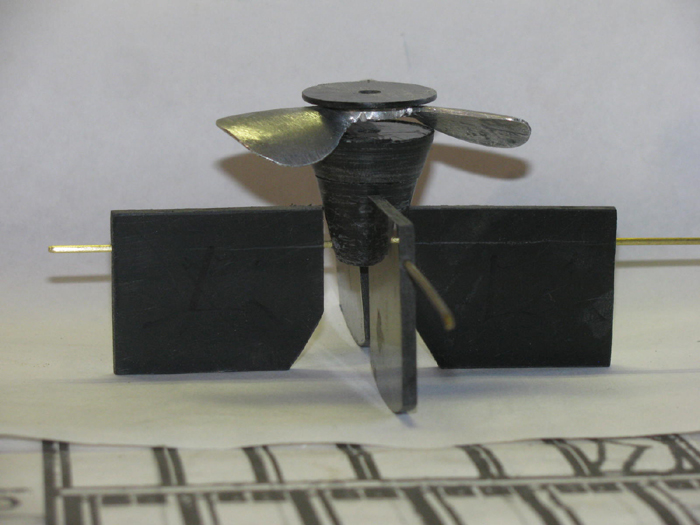
Looking front to back, straight on.
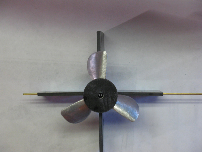
Side view.
You can see how much I have to inlet the blades in to the hub.
The hub is 1/2" thick when finished.
It is sitting on top of the tail piece .
The hub is about 3/8" above the rear planes.
The rear planes need a little material added to make them even with
the rudders.
Maybe 1/8".
Once I get the propeller set in, I will need to look over the look over
the placement of the rubbers and elevators.
To make this work, I needed to change the point of rotation of the
planes and rudders.
The original did not have part of the surfaces forward of the rotation.
They were not balanced controls.
This boat will have a little.
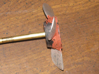
I have inlet the prop in to the hub.
I put some glaze on the blades and then plastic cement on the plastic
contact surfaces.
The parts are on a shaft to keep the aligned.
I used the drill press to put pressure on the parts.
Raised the table to produce the press while the glue cures.
Went on to the tail piece behind the propeller.
The piece that has been turned is the bearing support of the tail group
control surface rods.
I could make that spinning in the drill press because I could make
a hole all the way through.
The end piece will be hand shaped
Here, I cut lots of plastic pieces with scissors.
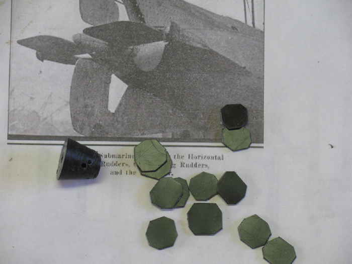
I glues each one as I stacked them.
Then I clamped them with a small clamp.
I think I can drill and put a screw in the front end without coming
out the back end.
If so, I can spin this part as well.
Then glue it to the front half.
Removed the assembly from the drill press after glue cured.
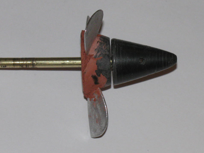
I have filled the gap where the propeller is and the gap from cutting
in the propeller in to the hub.
Side view.
A little more glazing on the propeller hub.
Rough shaped propeller tail piece.
Next, I need to be able to lock the propeller to the shaft but make
it removable.
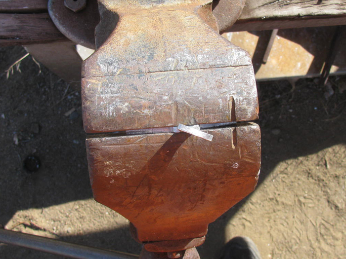
My solution is to embed a 3/16" wheel collar in the hub.
First, I put a short stainless shaft piece in my little vise.
It only sticks up to the bottom of the hole I want.
Depth of wheel collar plus.

Place propeller on the shaft.
I drill a 3/8" hole down to the shaft.
With the rotary cutting bit, I line up the cutter to edge of the 3/8"
hole and clamp vise to drill press table.
Run the rotary bit down to the shaft and turn the propeller on the shaft.
This will cut the bottom flat and to the correct diameter.
I ground 2 sides of the wheel collar at an angle.
I drilled a hole in the side of the hub to meet the set screw hole in
the collar.
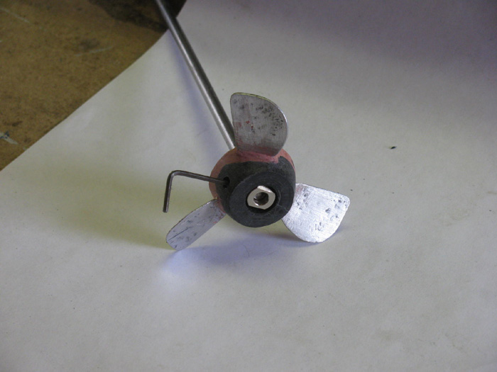
Greased the shaft and set screw.
Applied my expanding glue in the hub hole.
Placed wheel collar in and ran the set screw in to the hub but not
against the shaft.
There is enough plastic hub to keep the propeller straight on the shaft.
Tightening the set screw would push the hub off center.
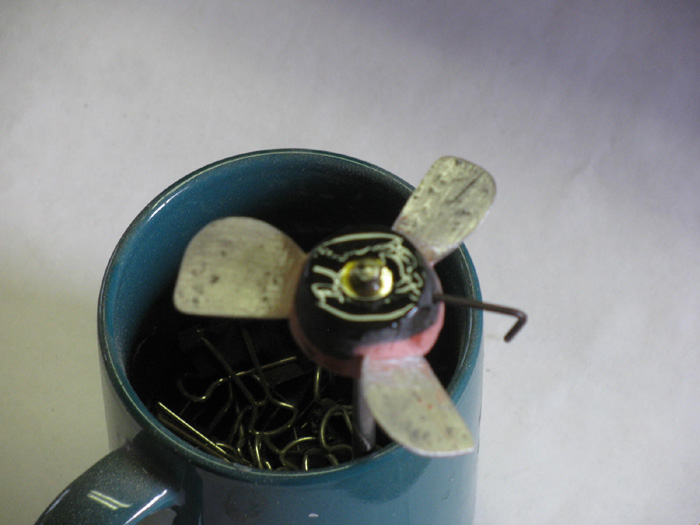
Wait 17 hours and remove shaft and set screw.
Glue is not completely cured and these things can be done.
24 hours, it is possible that I can not get the shaft out or the set
screw.
|