| This is all Will Oudmayer fault.
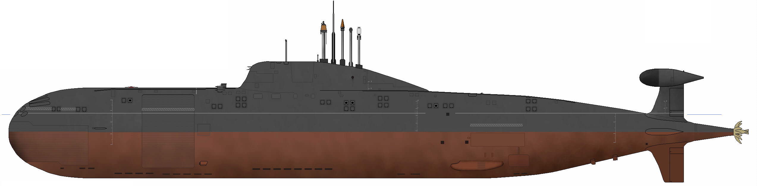
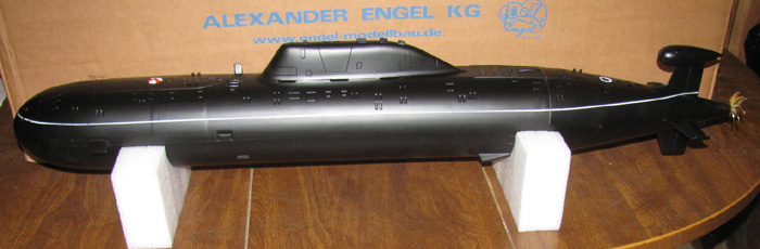
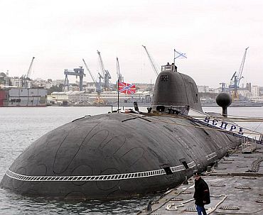
At the last gathering of the suborn LA, Will had a new Engel's Akula
II.
I really like the looks of the Alpha and Akula boats.
Will talked and I listened.
He talked about how it ran, how it assembled and on and on.
I had a couple of questions and he had a brochure.
I asked to take the brochure home and return it at the next gathering.
I read and reread the brochure.
I went to the Engel's web site.
I ran cost numbers against my other builds.
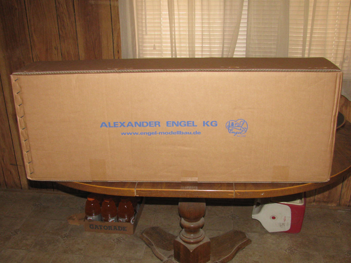
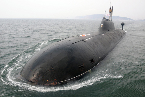
What did all of this do ...... I ordered an Akula II last Wednesday
and it arrived today, Monday.
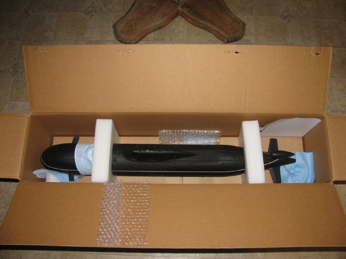
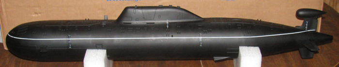
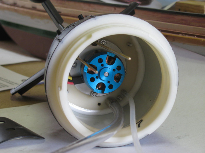
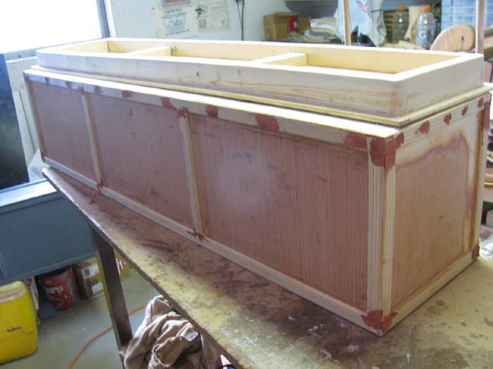
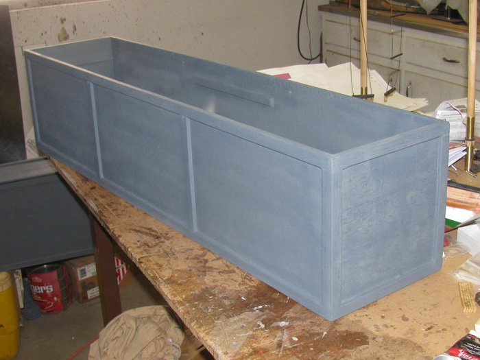
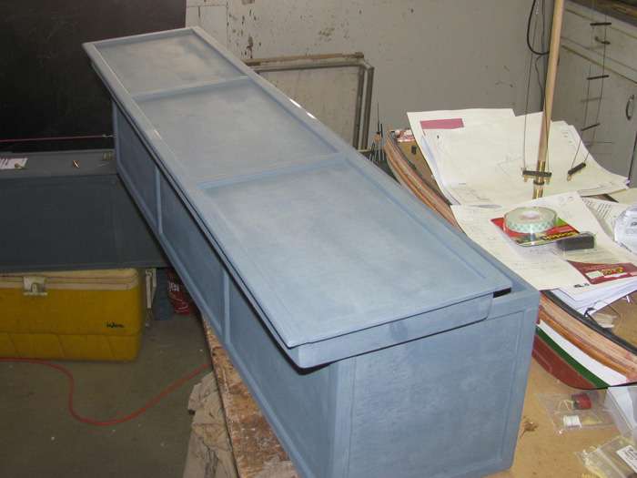
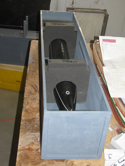
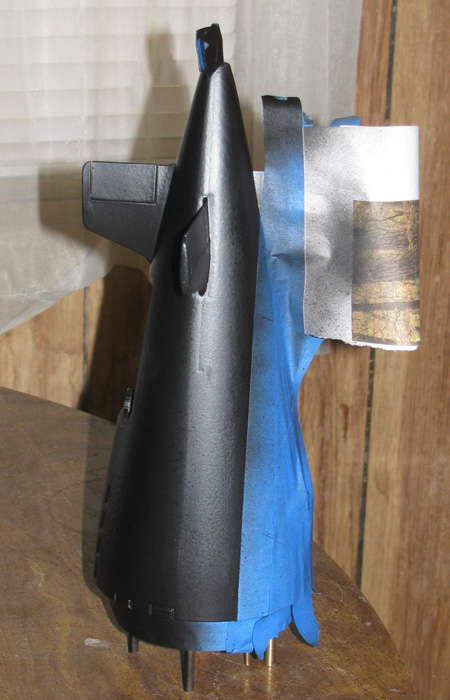
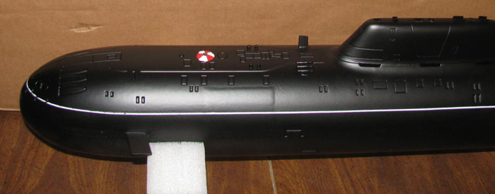
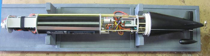
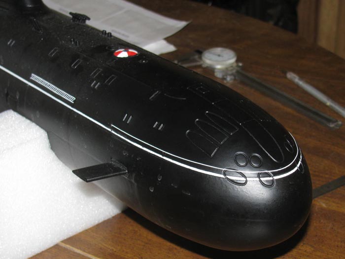
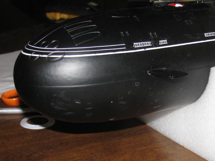
This is what it looks like after removing the brown paper shipping paper.
Okay, settle down.
I will show you what is in the box.
The boat is on top of two smaller boxes that have all the parts inside.
I know you could not wait.
Me either.
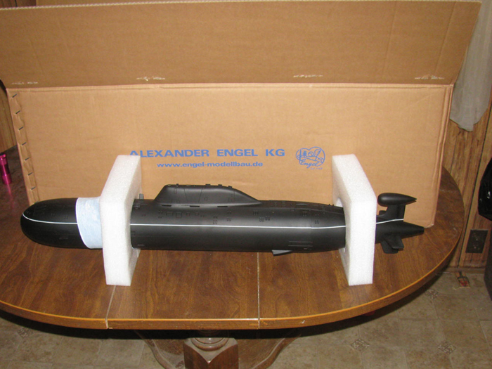
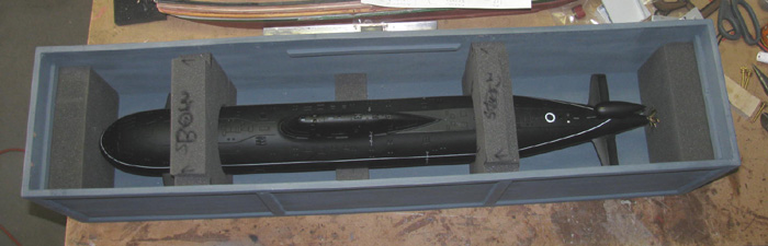
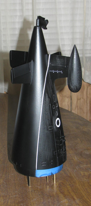
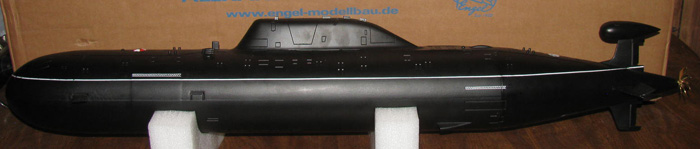
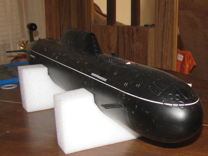
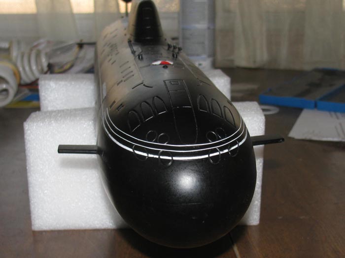
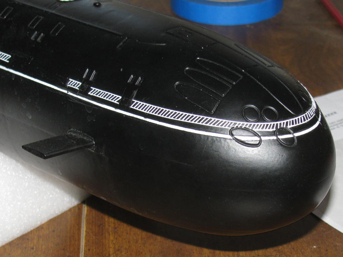
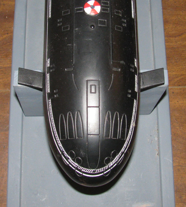
This boat comes, hull painted and assembled with bayonet rings installed.
Boat is 35" long and 4" in beam.
Width at stern and bow planes is 6".
Box weighed in at about 18 pounds.
====================================
Will said several times that I should follow the instructions and dry
fit everything as I go.
He said near the end there might be a couple of items that will need
repositioning.
Well, I am going to take his advise.
His Akula II runs pretty good.
Then I learned it was the first run not in the test tank.
----------------
Assembly Starts. . . . .
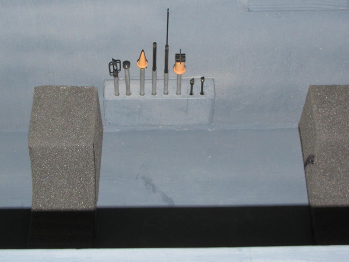
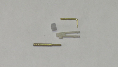
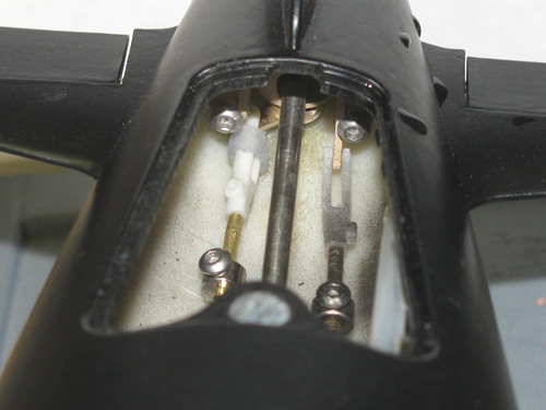
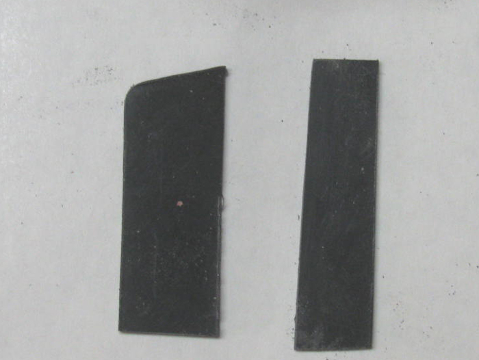
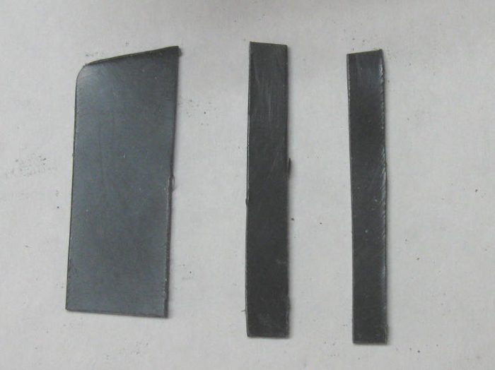
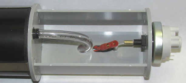
First thing to do is . . . Inventory all the parts.
Done ! Lot's of individual plastic bags. All numbered.
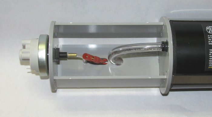
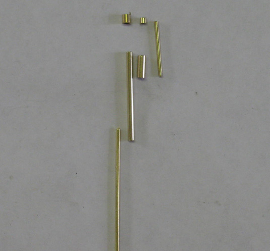
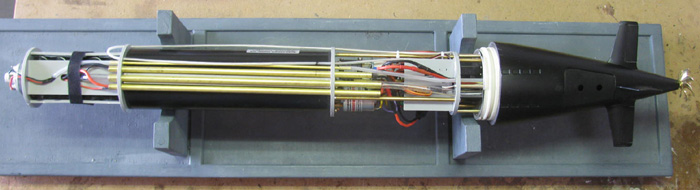
Step 1 - Install 4 brass tubes under piston
Did not take a photo but you will see the tubes as I progress.
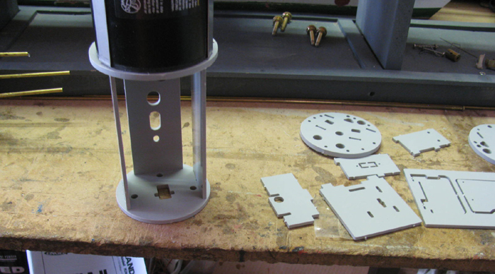
Step 2 - Build the battery tray and joining 2 battery packs
Found the 4 parts needed.
During dry fit, it was clear that a little Exacto Knife work cutting
the plastic parts from the mold tree.
These 3 parts were already removed from the tree by the factory.
Test fit the tongue and slops.
All the 90 degree inside corners needed to be squared up with a small
file.
The parts did not sit flush to each other.
File the tree sprue down flush.
1 or 2 passes with the file and the fit is good.
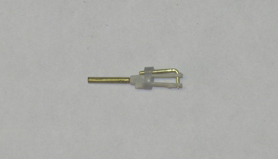
The battery tray glues right to the forward frame mounted on the piston
tank.
Using medium CA glue as per instructions, I did the piston end of the
parts and plug them in.
Next I did the out board side and plugged in the end frame.
Held it together by hand for a couple of minutes and then stood it up
on end letting the piston put down pressure on the assembly.
So far the instruction are clear and have a drawing with part numbers
and orientation.
While waiting for CA to cure, I moved on to the batteries.
The kit comes with 2 - 6 volt battery packs.
System runs on 12 volts.
Following the instruction, You solder the black lead of one battery
to the red lead of the other battery.
The instructions tell you how long to make each lead.
Tells you what size, how long and when to slip the heat shrink tube
on.
Make up the plug connector.
The 2 battery packs are not fixed together.
They will sit in the battery tray with a gap between them for wires
and tubing to run through.
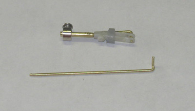
Here, I have started removing other parts from the plastic tree.
Clean up the edges and square the inside corners.
Test fitting each one as I go.
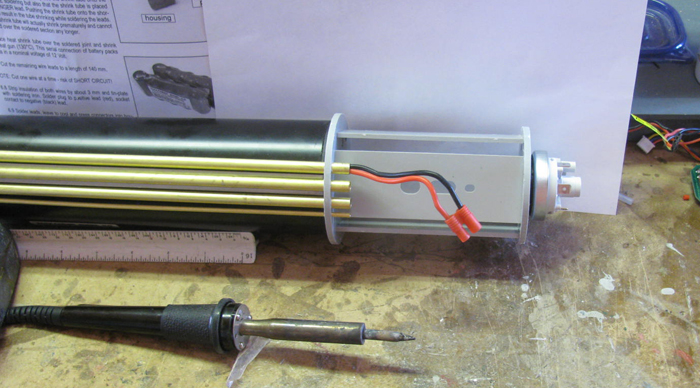
Step 3 - Running main power wires
There are several brass tubes under the piston for running various wires,
water and air.
Following the instructions, I started pushing the a Red and Black wire
through the brass tube.
The tube is 12" long and I was able to push, at beast, 5" or wire.
The wires are just a little to big and soft to push through.
Tried using a string tied to the wires to pull them through.
The thickness of a simple string was too thick to even start in to
the brass tube.
Looked on my material table and found a brass tube that slipped inside
the boats tube.
Soldered the two wires in the tube end.
Cleaned up the end of the tube of solder with a small file.
Here you can see the tube I used with the wires soldered.
Pulling did the trick but it was still a hard pull.
Unsoldered the wires from the brass tube.
Made up the power plug end.
This end plugs in to the battery plug.
Behind the plug you can see three hole in the bottom of the battery
tray.
There are 2 - 6 volt battery packs, more wires and a couple of air
lines go up between the batteries through those holes.
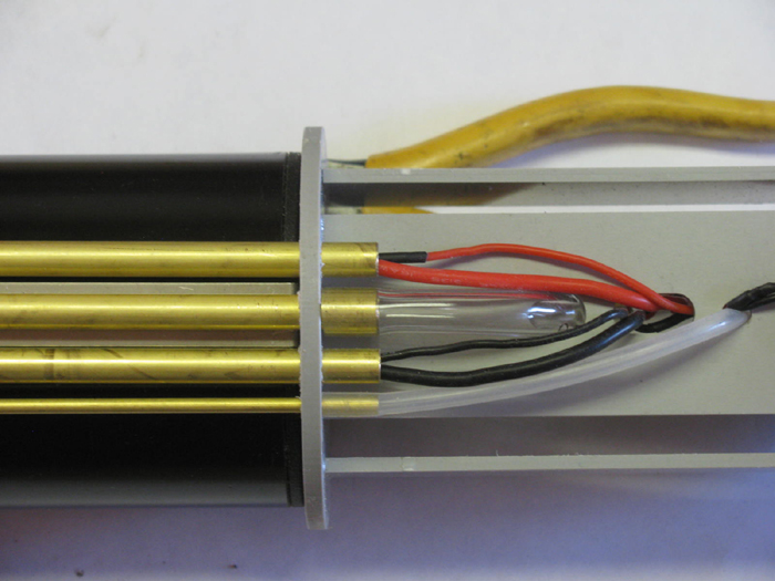
Step 3 - Special note!
Today was a suborn LA gathering.
Talking with Will Oudmayer on my Akula
II progress.
I explained the above issue I had pulling the main battery wires.
Will said he had similar issues and took me to his boat sitting on the
picnic table.
He picked up his tech rack and turned over to show me what he had done.
He had read farther in to the instruction and learned that the remaining
brass tube was for the pressure sensor wires.
(this happens farther down in the instructions)
What he did was brilliant.
To solve the problem of pulling the 2 power wires through the tube,
he took the black power wire and the black sensor wire and pushed them
through one of the tubes.
Then he did the same with the red power and red sensor wire in the
other tube.
This was so much easier and the reason was, 2 power wires just barely
fit with a lot of effort.
The sensor wires are half the diameter of the power wires and Will's
way left plenty of room in the tube.
It took me 5 minutes to unsolder the sensor wires and pulled them out.
I pulled the power wires out the other direction because one end had
not been connected to anything, yet.
So, I pushed the smaller wire through and then pushed the bigger power
wire through the opposite direction.
This require almost no effort at all to accomplish.
This does require lengthening the Sensor wires. (you can see the heat
shrink tubing on the two wires.
Resoldered extra wire in and then to the sensor.
Will's solution will allow mush easier repairs late should they be necessary.
Here is how it looks now.
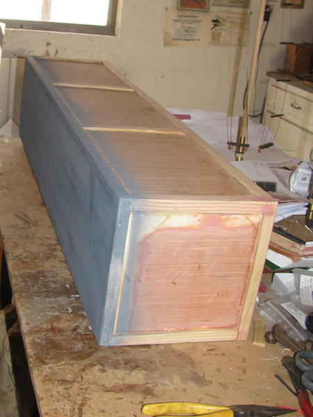
Step 4 -Center Section
The part on top right is removable and will be screwed on later.
To keep this group of parts squared up, the top is sitting in place.
It has tongues and slots that keep it very tight.
From this point I had to back up 1 step.
The parts on the right mounted to the brass rods was not suppose to
be installed yet.
My fault. . the instruction book fell on the floor and when I picked
it up the page had turned but looked almost the same.
The next step has me installing the two servos but with the part installed
on the brass rods
There is no way to put the servo tabs in their slots.
I removed the frame and set it aside.
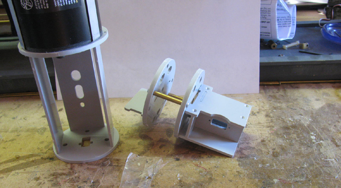
Installing the 2 servos.
In the 2 frames you can see 2 angled slots in each frame.
The servo tabs just slide in and the second frame is held in place
with 2 screw in to the brass rods.
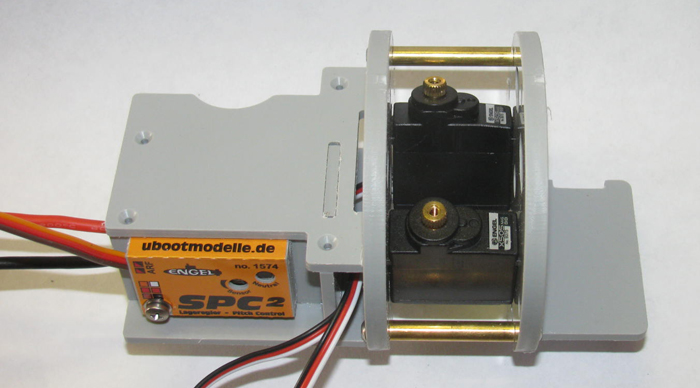
During the dry fitting, I noticed that the servo plugs will not go through
the frames as instructed.
The plugs hit the frame of the completed box with the removable top.
Each servo has a rectangle hole where the servo wires come out of the
case.
I can not disassemble the box so my fix was to use my exacto knife
and taper the top edge of the hole.
Not enough room to go down but plenty to go up.
I slowly cut away the soft plastic until the plug would slant up and
tilt between the frame and the box.
Cleaned up the hole edge with a small file.
Servos and Pitch controller. (Pitch controller will be removed and reinstalled
later)
Step 5 - Water Tubes
The main water inlet to the piston attached and run through the tray
hole and on tot he center brass tubing under the piston.
Also, the pressure sensor tubing is installed.
From the pressure sensor to the small brass tubing under the piston.
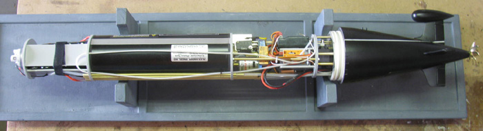
Step 6 - Mounting electrical parts to piston end
2 wires needed ends soldered on and then soldered to the motor terminals.
The 2 wires are not on in this photo.
They go from the motor terminals to the bright blade terminals
on the 2 limit switches.
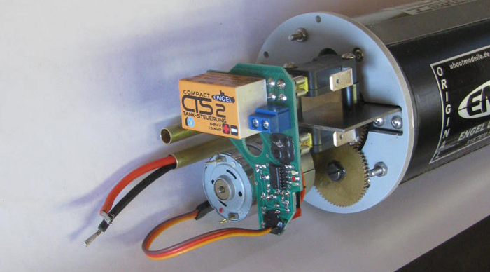
Mounted the center section to the back of the piston.
This will have most of the equipment.
2 servos, main power disconnect, Rx, Speed Controller and BCE.
May be more but I have not read the instructions beyond here at the
moment.
Continuing to wire main power from battery to main plug and then on
to the various components.
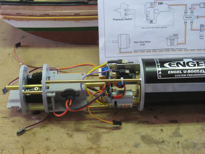
Step 6 - Wiring the Speed Controller, UZBEK and BLS
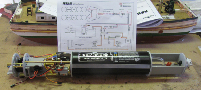
Building the tech rack out in the shop and have the hull sitting on
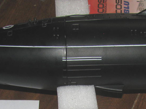
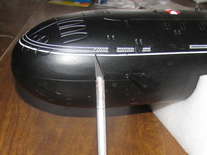
the kitchen table.
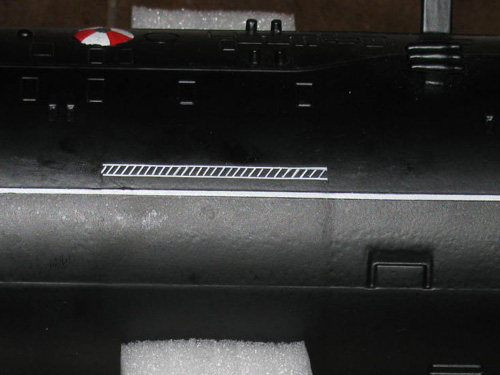
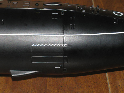
Thought I would put the draft marks on the hull.
4 on each side of the hull.
Decided not to use the thick lines that are above the waterline centered
over the forward planes and below the waterline just aft of the sail.
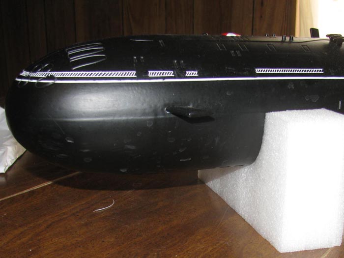
(interesting that in the photo the forward planes
did not show up. They come installed from the factory)
Of Interest: Before
applying decals, consider the following.
I used the supplied drawing to apply the draft marks.
I did not use the large solid lines.
Reason was, where the drawing shows to put them is incorrect.
The forward draft marks are shown where the forward solid line goes.
Did some research and found several Akula II drawing.
They all where a little different.
Must be to the variations during building the real boats.
However the draft marks and solid lines seem to be located in the same
places.
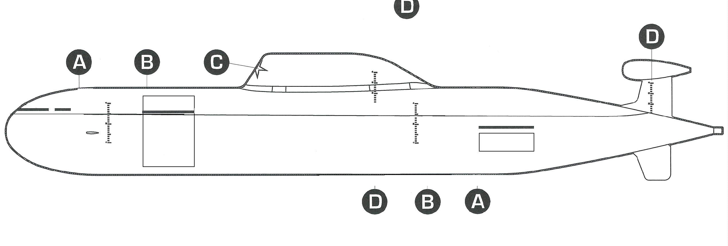
I modified the supplied drawing above using one of the drawing I found
in my search.
I started by locating the solid lines.
Always wondered what they were for, these large double lines on the
real boats.
The drawing I found seem to have them located to show where the side
sensors are.
Even the one that wraps around the bow.
The bow and forward lines are above the waterline.
The rear one is below the water line and above the sensor panel.
My suggestion if you want to use the solid lines in the kit, start
by placing the solid line before the draft marks.
These solid lines are located to show the location of the sensors.
The forward line is on the sensor and the aft line is above the sensor.
(click on the above images to see large view)
To make this easier, only the forward draft marks need to be relocated.
The sail, rudder and mid ship draft marks are close enough.
The bottom drawing shows draft marks in front of the rudder, however,
I could not find a photo of a real boat with these marks. (there may be
a boat with these marks, but I have yet to see it)
Now for the forward draft marks.
They are just aft of the forward planes.
I did some scaling and here are some numbers starting at the bow.
These numbers
Front Draft marks are located at about 5.25" (133.00mm)
Sail Draft marks at about 16.75" (425.75mm)
Mid ship Draft marks at about 20.06" (509.63mm)
Forward of rudder draft marks ? are at about 25.87" (657.15mm)
Rudder draft marks at about 31.18" (791.20mm)
The scale numbers are not exactly the same as the lower drawing.
Example. . .The forward draft marks are moved aft 7/16" to clear the
planes.
==================
Building is on hold while I wait for an option I did not order originally.
I could go on but if I wait for the parts, it will be much easier to
install with the next step parts not installed.
So, the build of the tech rack is on hold. (Parts are do here
next Wednesday . . .6 days from now)
But there are things I can do.
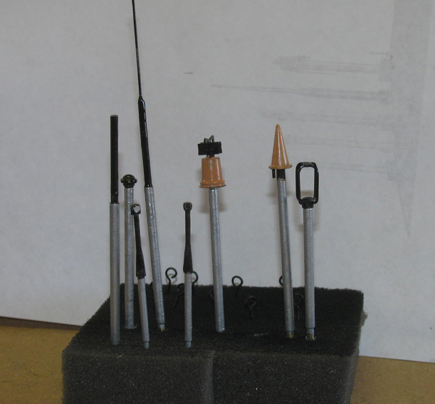
The provided masts are some sort of molded plastic or polymer.
They are very fragile and I had one break that rolled off the work
bench on to the floor.
They would look good for a display model but I do not think they will
stand up to more than one or two in water patrols.
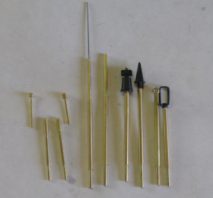
So, I will make New Masts.
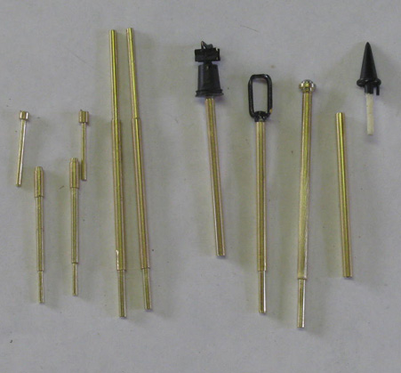
I put several sizes of brass tubing and brass rod on the work bench.
Using the original parts as my guide and a nice photo of the Akula
I masts extended, here I go.
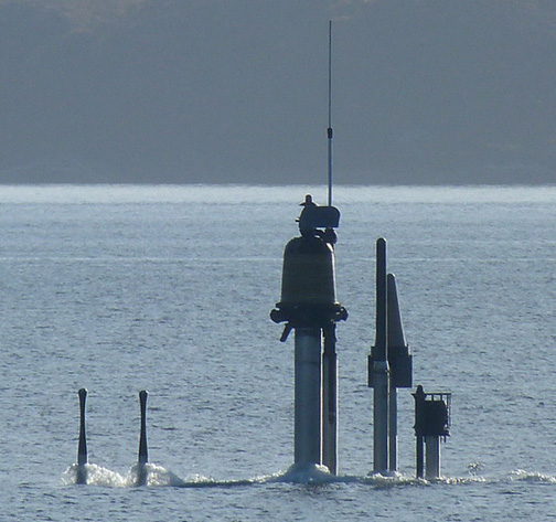
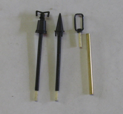
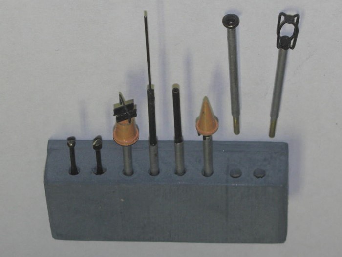
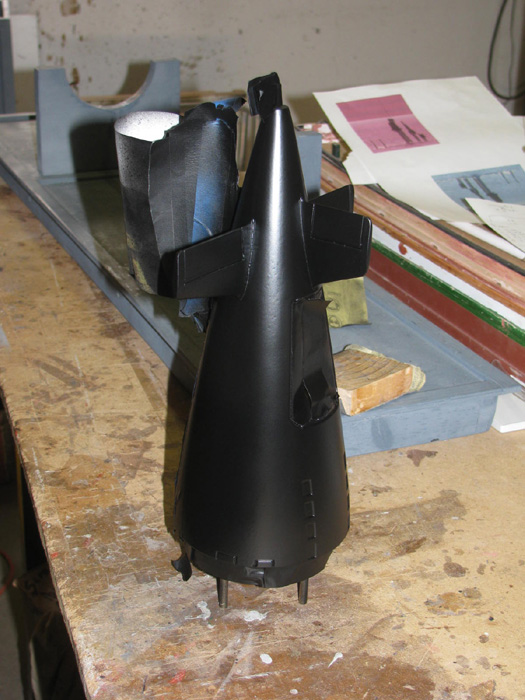
Building the two periscopes.
In the photo above, they would be the two masts on the left.
From the bottom up.
Will be the pin that holds the mast to the sail.
Mast tube is brass tubing.
Near the top is a brass tubing sleeve that will be shaped tapered.
Above the tapered part I used a brass rod.
The two heads are made up of brass tubing rings which will be shaped.
The shaping will take place before installing the top to the bottom.
The parts are glued together less the bottom mounting pin.
Below are two original masts and one I have started to modify.
I cut most of the mast off the part and filed it down to fit inside
the brass mast tube.
I tried using the Dremel grinding wheel but it melted the plastic mast.
The small file only took a couple of minutes and I had much more control
in fitting to the brass tubing.
Once I had all the parts cut and fitted, I just glued the plastic parts
in to the brass tubing.
I lined up the masts to get the correct length before installing the
pin that goes in to the sockets in the sail top.
Still assembling masts.
Here is what I have so far.
I still need to work on the two periscopes.
Can not assemble them until I do so shaping of the lower mast.
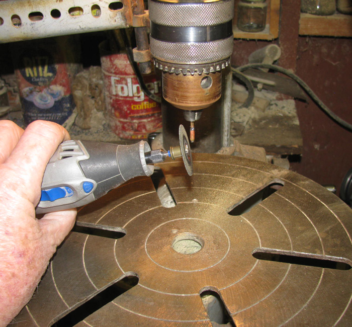
Time to turn the periscope tapers.
In the drill press ready to turn.
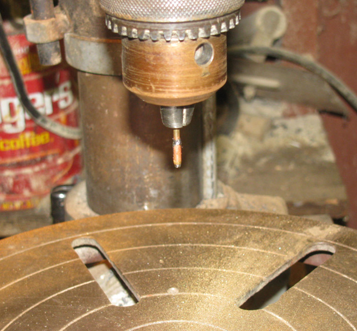
Using the Dremel at an angle, I ground a taper on the part.
The pointed end has a hole in because the shaft is a tube.
I have assembled the periscopes. (two on the left)
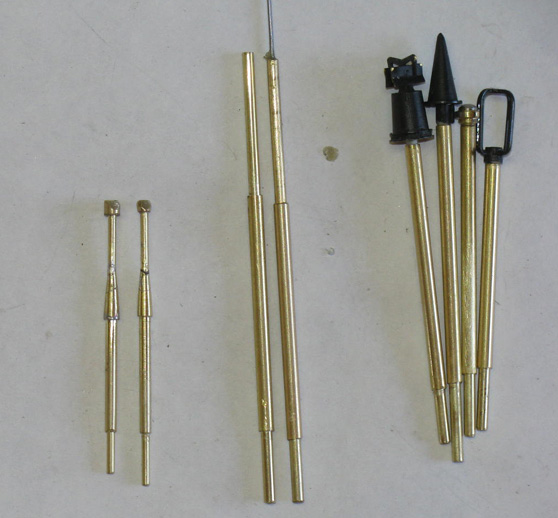
Painted the shafts silver.
Some parts are black and some are a light brown almost a pale yellow.
Didn't have the yellow so, it is more of a light brown.
The black looks bumpy but it is still wet.
I just finished the black and it has not had time to flow yet.
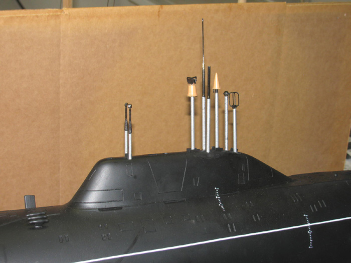
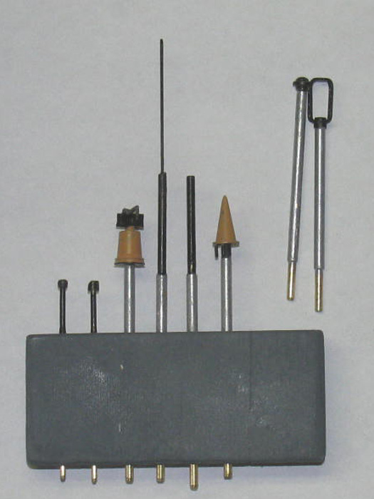
New masts in place.
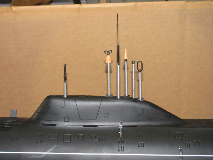
They are not installed permanently.
They all have pins in the bottom that fit in to the sockets installed
in the top of the sail.
A little bit of silicone grease on the pin and they stay put but are
easily removed.
Tip: making
mast sockets straight.
This has always been a problem when there are
more than two masts.
Here is how I do it.
I drill the holes in the top of the sail by hand
twisting the drill bit that is the size of the socket to be used.
(there are two different size sockets
in this sail)
I make up a setting tool.
In this case, I use tubing and rod.
The socket is the same size as the mast shaft.
I get a short piece of tubing the same size as
the mast shaft. About 2" long or so.
Long enough to hold on to and control.
The rod or tubing that goes in side is longer
by 2" or so.
I push the inside piece through and have about
1/2" sticking out one end.
I tape the other end to keep the pin in place
and does not move.
Then a piece of tubing or rod that will fit in
to the tubing which is the same size as the pin for that socket.
(the pin can be tubing or rod. What
ever fits)
I cut up the number of needed sockets of that
size.
I make them about 3/8" long. (the pins are about
1/2" long)
Using the tool I made, I put a bit of silicone
grease on it to hold the socket while I work.
I then put a small amount of glue on the sides
of the lower end e of the socket.
Using the tool, I push the socket in to the hole in the top of the
sail.
By eye I try to get the socket straight and plumb to the hull in both
directions.
Once the socket is in place, a slow twist of the tool will release it
from the socket and can be removed.
Install all the sockets.
I use a slow cure glue for this.
After about 15 minutes, I carefully put the masts in the sockets making
sure not to push them deeper in to the holes.
With the masts in the sockets, I can look down the hull and straighten
the mast up.
However, some will not be straight as the holes where drilled by hand.
Make sure to remove the mast so if there is any glue in the socket
the mast are not permanently glued in place.
I can fix any masts that are not straight.
After a day ot two of curing, I can clean up the sockets and put the
masts in their sockets.
Now you can see which masts are not straight.
Using the tool I made earlier, I can heat the pin by putting it on my
soldering iron.
Be careful about hot hot you get the tool.
Start slowly with low heat and increase if you need to.
When the tool is hot, insert it in to the socket you want to move.
Apply pressure in the direction you want the mast to move.
Remove the tool and insert the mast to speed up cooling.
Basically, you are melting the glue and in some cases you at softening
the model material to move the mast.
I had to move 4 of the mast sockets and the time needed was about 10
minutes to do all of them.
The big WARNING is,
Do not get the tool too hot.
It will melt the model and repairs are not something I want
to do.
======================
Still waiting on a couple of parts from Angels.
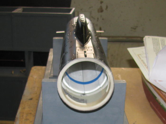
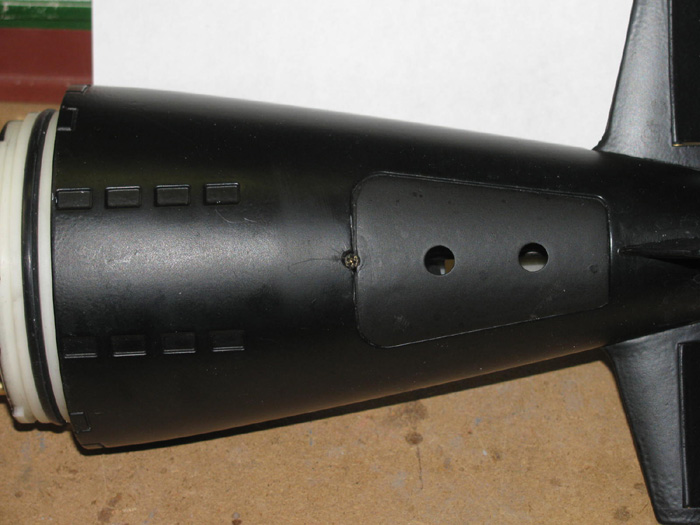
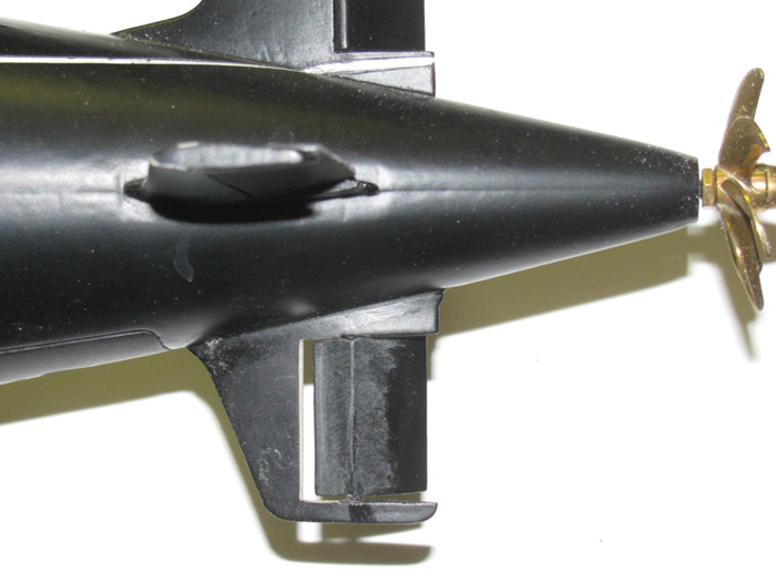
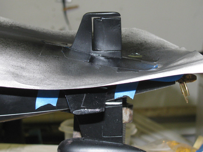
Step 16 - Moving on to the Tail Cone. . . . . .
Here is the tail cone removed from the hull.
There is a small access hatch on the bottom of the tail cone held in
with a tab and magnet.

Hatch removed showing the back water tight bulkhead with control rod
bushings and seals already installed.
Control rod boots now installed.
They come with a O-ring that goes over the end of the boot and holds
it on the end of the bushing which has a groove in it.
Step 17 - Control rods installed with wheel collar retaining clamp.
Step 18 - tubing and bars. . . .
To the front of the tail cone, next the water hoses are installed.
They are pushed on to the tubes already installed in the water tight
bulkhead.
At this point the instructions say to install 4 brass rods with tapped
ends on to the bolt studs in the tail cone.
I did this and quickly found out, they are going to be in the way of
the next step.
I removed them and will install later.
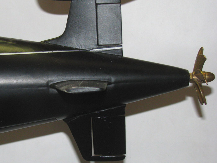
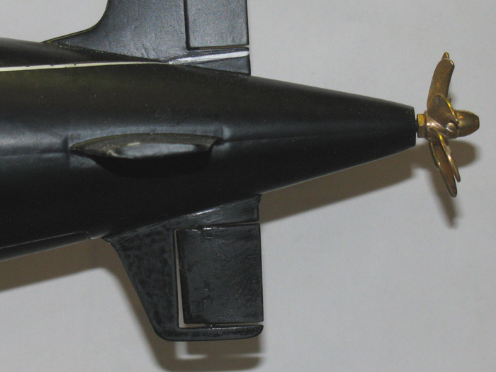
Step 19 - Main Drive . . . .
Assembling the drive shaft.
First the connector to the motor shaft and then to the propellor shaft.
In stall seal in to the motor mount tail end.
Press fit making sure to get the seal facing in the correct direction.
Grease tail shaft housing and slide O-ring on part way.
Now for some fun, slip the motor mount assembly in to the tail cone.
Make sure to get the motor wires in the correct location .
The fun is trying to get the 4 small nuts started on the bolts already
installed in the tail cone water tight bulkhead.
I found a skintight wrench that fit and was able to tighten the nuts
up after I got them started and finger tight.
After the motor assembly is installed then I put the 4 brass stand
off rods back in.
===============
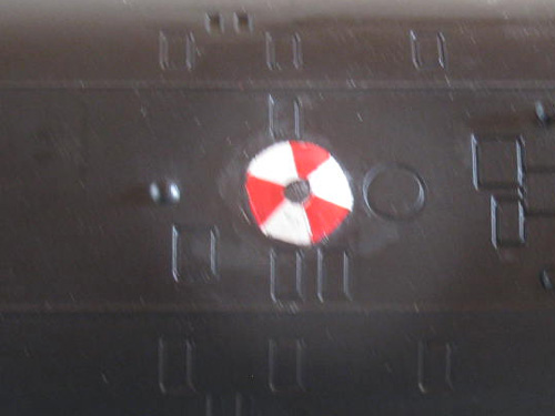
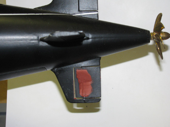
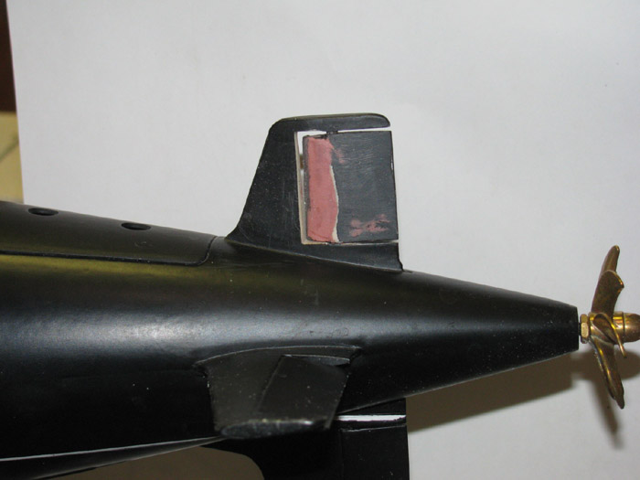
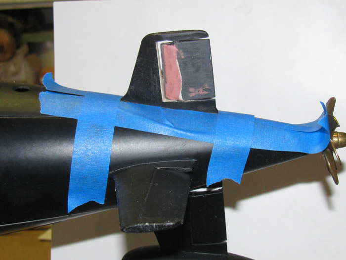
Painting Emergency Buoy.
Well, I tried 4 times to get the paint straight.
I think I have finally have something I can live with.
Painted the buoy white to start.
Waited 3 days for the white to cure. (I didn't on attempt 1)
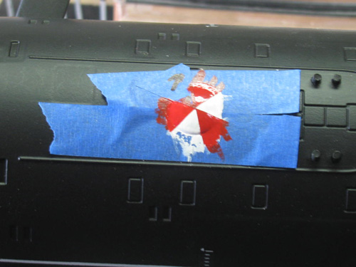
Removed the tape
Now there will be touch up.
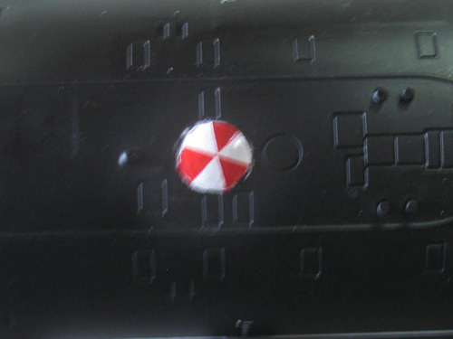
The black and white have been touched up.
Still need to do the red.
I am taking my time and letting the paint dry before the next step.
I think I can live with . . . if I don't mess it up. (I can always sand
it and paint it black)
I decided to use a paint brush that has 4 hairs instead of my 1/8"
brush which was too big.
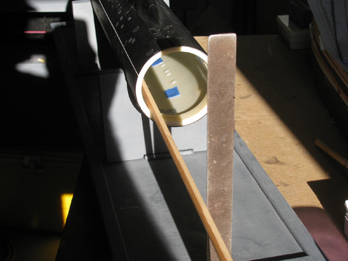
Reference . . . . . buoy is 5/8" in diameter.
==================
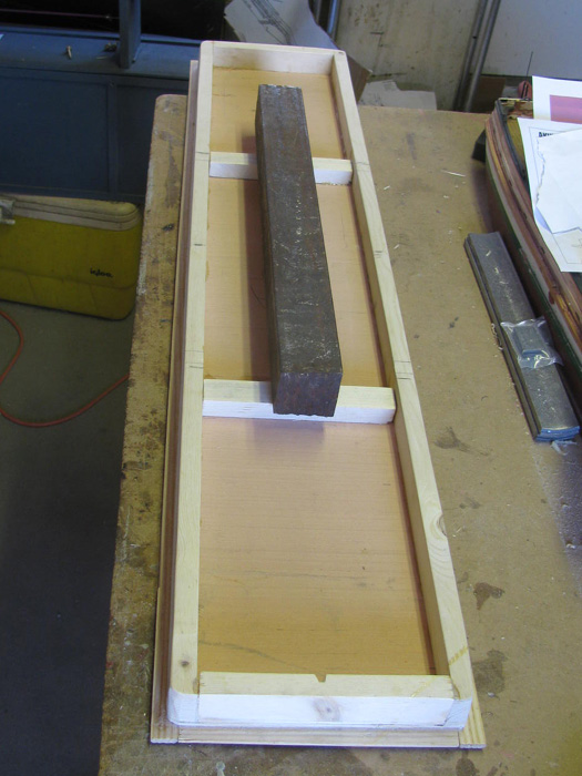
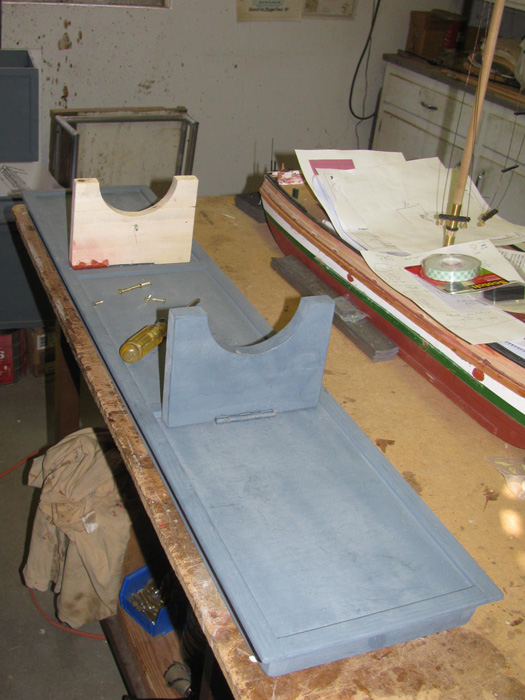
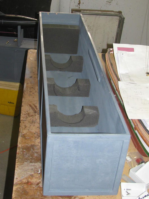
A Transportation box for the Akula II
While waiting for the parts to arrive, I moved on to building the transportation
box.
I have the materials, so why not.
All the measurements have been taken.
Lumber and wood panel have been cut.
The sides and one end glued and clamped.
Other end is just set in place and held there by the sides springing
in.
Why only one end?
The end is to keep the sides square to the bottom.
This end had all the panels square with the bottom which is 3/4" pine.
At the other end, the side panels are about 1/16" long so I can belt
sand the panels down to the bottom piece.
Also, I will install the end panel but I need the box to be sitting
upright so I can place a wooden block I have that has all it's sides squared.
By clamping the block tot he bottom I can move it until the end panel
is flush with the side panels and then glue the end in.
After it cures, I can sand the side panels down to the end panel.
Edges on end have been sanded flush.
On to trimming the box.
Working on one side, I have glued the 6 pieces needed.
Clamps and weight to hold every thing in place.
Because the glue expands, I use a lot of clamps where I can.
If I can not reach a point at least there is one clamp to keep the
parts from sliding while adding weight.
I do not have enough long clamps to do the bottom trim strip.
So, I broke from my normal way of building these boxes.
I used nails on the bottom strip.
The box bottom board is 3/4" pine and there is room for nailing.
The corners and upper sides do not.
The panels are only. 3/16" thick.
The small square steel are solid.
The larger square tubing had steel rods put inside to add more weight.
Guessing there is about 100 pounds more or less sitting there.
All the trim is on the side.
Even cleaned up the glue that squished out from behind the trim boards.
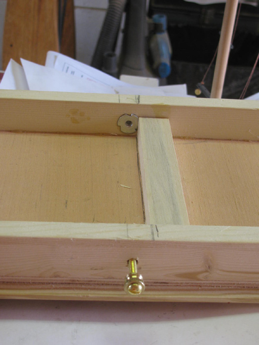
I have glued and clamped the inside rails that the top frame will sit
on.
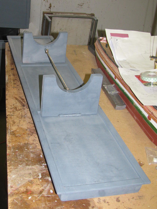
While I let that cure, I thought I would make the foam inserts that
will hold the boat in place.
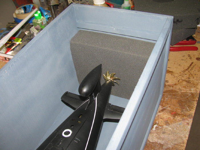
I made 2 end pieces that the bow and propeller will be against.
I made the box with foam 1/2" shorter than the finished boat to put
a little pressure on the boat while in the box.
Below is one of the 2 cradles that the boat will sit on/in.
The bottom piece is the short one.
Here you can see the inside rails are clamped that the top frame will
sit on.
Also, you can see the 2 center foam supports.
After the glue cures, I will set the top in and adjust the height by
sanding down the top frame pieces.
Once I get the top flush with the sides of the box, I will add the
trim boards to the top.
Top was set in the box and the lines drawn for the trim boards.
There is an overhang that covers the top edge of the box.
Underside of top.
Top of top.
I know, More nails!
Made up the four bolts that hold the top on the box.
Looks like I need 2 more blind nuts.
I will be in town this morning to get hinges.
Will get 2 blind nuts while there.
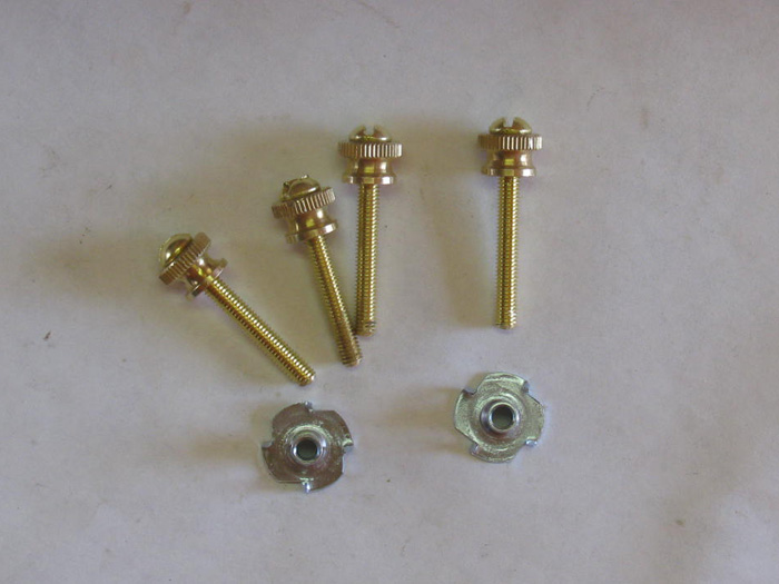
I got the last of parts at the hardware store today.
In this photo are the last 2 pieces to be glued.
These are the blocks that the hinge screws will go in to.
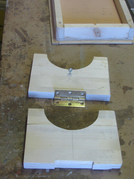
I finished shaping the 2 box lid stand pieces.
Inlet for the hinges and a screw eye for the small bungee cord that
keeps the stand up when using it.
With the top on the box, I drilled the 4 holes for the bolts that hold
the top on all the way through the top frame.
Then I drilled the holes in the top frame large enough to fit the blind
nuts.
Checked for fit.
Put a bit of glue around the blind nut shank and pressed in with my
small drill press vise.
Blind nut installed, it is time to start glazing the box.
Glaze all the trim joints, corner gaps (only one) and the counter sunk
nail holes.
Later today, I will sand the entire box and reading for primer.
I do not paint these transportation boxes.
Only primer.
Makes it easier to touch up any scratches or dings the box may
get while handling.
Sanding has been completed.
An electric palm sanded took care of all the sanding in about 5 minutes.
A little Exacto knife work in the corners and ready for primer.
I like this kind of project.
I can round up all the half empty primer cans and use them up.
I do the bottom first.
This way, I can see if the different cans of primer are the same color.
If not, I use these on the inside where they really don't show up well.
Note: These photos are taken on my shop work bench.
However, all painting done outside on the metal work bench.
Turn the box on end and paint the inside.
Time to do the inside of the lid.
It may be a few days before I can get back to this.
Report for jury duty tomorrow.
Usually they dismiss me and send me home but I never know.
Only good thing about this is, the place I get paint/primer is on the
way home.
I can stop and get more primer to finish the box.
Went to the court house.
As expected, I was dismissed.
On way home I picked up the primer and a few other items.
Did a little sanding on spots I glazed after priming yesterday.
Primed the entire box.
And the lid.
The primer is not like it use to be.
It covers but it does not fill.
I may end up painting this box with flat gray paint to fill the grain.
Mounting the lid stand.
I am still glazing the one, so it is not primed yet.
Boat stand installed on lid.
Retaining bungee in place.
Just a small spot on the back ones lower left corner.
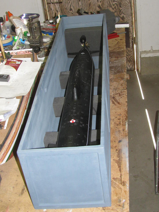
Laid out the locations for the support foam.
Installed 3 and 2 ends.
Used a few spots of clear silicone caulking to hold the foam in place.
Easy to remove if need be.
Here are photos of the boat sitting in the transportation box.
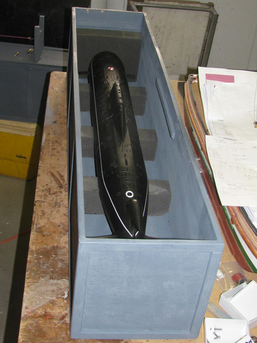
Add the compression foam.
The foam is cut to fit the hull with about 1/16" clearance.
The top of the foam is 3/16" higher than the bottom of the lid.
The lid will compress the foam down 3/16".
The hull will not move.
A look straight down in to the box.
Lid set in place and the lid bolts put in.
This requires me to push down on the lid while screwing in the bolts.
1 stand up and 1 stand down.
A small bungee cord hooks in to the eyes on each stand to hold them
up when placing the boat on the stand.
The transportation box is complete.
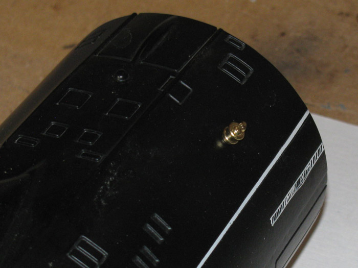
I found in the instructions showing how to plug in the Hall Sensor and
the 2 jumper plugs in.
Looked right over them.
Did the connections and ready to move on.
While it was early and when the sun comes through the shop door, I decided
to go with marking the inside of the hull for the ballast weights.
Need a center line.
Easiest way I could think of to do that was to use a square to level
the hull in it's stand.
By using a square and another square clamped to it, I could cast a
shadow that I could use to get the hull level.
The shadow from the 2 squares was used to get the forward planes level
by splitting the shadow in the rear of the planes.
Then I moved the hull until the shadow was centered in the opening in
the hull.
Moving the hull side ways I got the shadow to split the hull down the
center of the deck.
Turns out that the shadow from the sail centered right on the forward
emergency buoy. (good reference)
With the boat level and the shadow centered down the hull, I could use
the shadow in the hull to place marking tape on the center line.
Using 2 long sticks I place the pieces of tape.
(Tape to be removed later)
This process took me about 15 minutes.
I have used this method of shadows to make center lines and long straight
line on other projects in the past.
I found that in the field working, I could almost always get a shadow
line for job layout.
Hull inside centerline in place.
Was doing this and I realized I have a problem.
I have all those masts sitting on the work bench stuck in a piece of
foam.
I keep knocking it over.
Time to fix that.
Took a block of wood and marked it up.
Drilled pilot holes through the block.
Then I drill larger holes to accept the masts down through the block
leaving 1/4" of small pilot hole left in the block.
The pin that holds the mast in the sail go through the block and stick
out the bottom.
Measured to make sure I had room to put the lid on and glued the block
in to the transportation box.
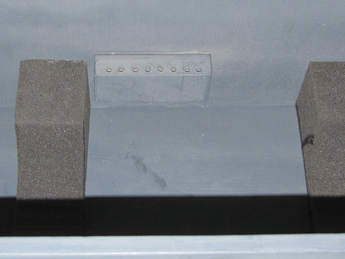
Now I have place to put the masts in the box, out of the way.
Clear coating the hull.
Well, this did not go well.
I asked Will how he prepared his 2 boats for clear coating.
Also asked what paint he used.
I cleaned the hull with Dawn dish soap and I bought the Rust-oleum Matt
clear coat as Will suggested.
This is what I got.
This is after 8 hours drying time.
The paint instructions say to allow 24 hours between coats.
The high ridges are getting lower but I think I am going to have a lot
of sanding with 400 paper.
I will take my time.
There is no reason to rush which from my experience with painting only
make things worse.
Maybe after 24 hours it won't be so bad.
------------------
The clear coat was a complete failure.
Checked in to getting new decal sheet.
I can.
They are back ordered 3 to 4 weeks.
Talked with Gregor at Engels and learned what they use for their waterline.
Decal tape.
They can not send this.
Did some searching and found where to get it.
They have several sizes.
Okay, I now have options.
Sand the clear coat down and see what I come up with.
Sand the clear coat off which will no doubt take some of the thin black
paint with it.
Remove the decals and sand the areas smooth.
So, I am going to tape from the waterline up and see what I can do with
the bottom of the boat.
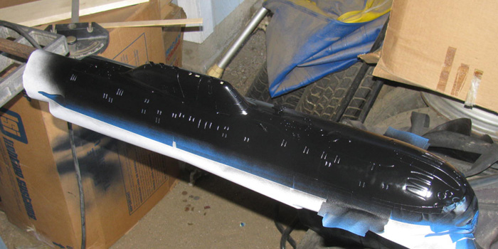
Spend two days slowly sanding the hull bottom.
I got it to where I thought I would put a first coat of flat black
on.
As I was painting the temperature turned cold. 50s F.
Brought the hull inside where it was warm to dry.
Looking at the paint with a flash light, I can see blemishes every
where.
Looked at it 45 minutes later and the paint looks to be pulling tight.
This morning, I looked again at the paint.
It is looking much better but there are still blemishes.
There are less blemishes and those remaining are not as deep.
Out to the shop I go.
Sand it all again with new sand paper.
Work on the spots where the blemishes are the worst and sand it all.
Wiped it down with a damp rag to remove the sanding dust.
Looking outside, the wind is down some so, I am going to try painting
the hull and then move it inside as soon as I finish the painting.
Here it is just before I took it inside.
This looks so much better.
Look at that smooth bow curve.
This the main part of the hull.
I plan to sand the tail cone and get it ready for paint.
There is only 2 decals on the rudder to remove.
I just scraped them off and sanded the remaining decal film down.
Realized it is not even noon yet, here.
Went out to the shop and sanded the tail cone.
Taped it off at the waterline.
Sanded down to the tape.
Damp ragged it and found a big cardboard box.
Took it all out to my painting area and put on a very light mist covering
it all.
I thought this would help me see where the blemishes are so I know
where to focus my efforts.
Sure enough, the blemishes show right up. (Not bad at all)
Tomorrow, I will attach the blemishes and the rest of the tail cone.
I should be able to get a good coat on after that.
Then some light sanding for a second coat.
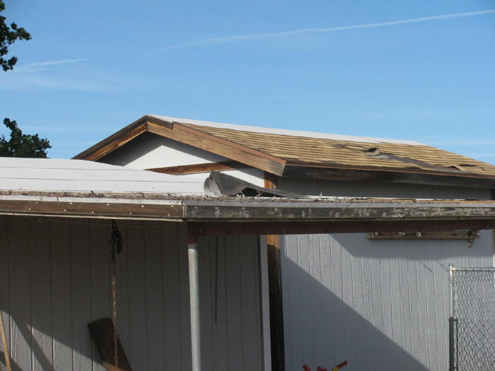
This morning and all night the wind has been blowing.
Not unexpected.
This is what awaited me when I went out to the shop.
Roof on extended roof of shop has left the area. (front building)
There is about 8'x10' of roofing missing.
Well, not missing.
It's on the ground in the backyard.
Roof on second outbuilding is in the process of relocating shingles.
Roll roofing or shingles.
Doesn't matter, . . the wind will always win.
Made out to the shop and removed the masking tape, covering the waterline.
I can not believe I got a very sharp straight line, right to the edge
of the white waterline tape.
So every happy.
Now, if I can get the same results when I do the top half of the hull,
I may through a party.
Spent about 30 minutes in the shop.
Block sanded and hand sanded the tail cone.
Wet ragged it to get the dust off and look for blemishes.
Sanded a couple of small spots and wet ragged it again..
Off to the shed and shaking paint can.
Painted and brought back in to the shop after 15 minutes of drying.
The only blemishes I can find are those between the rudder and rear
planes.
I think when the paint cures and tightens up, this will be done. (hoping)
If not, I am talking a 2" area.
The rest looks good.
Got up this morning and could not wait to look the tail cone over.
As I had hoped, the paint tightens up nicely.
I like it.
Liked it enough to pull the tape off.
Liking it even more.
Save the waterline so far.
Should be able to tape off and sand the above waterline surfaces this
morning.
May even get the first coat of paint on the tail cone. (I will get
it on there)
In this photo I can see the blemishes on the right and the repaired
surface on the left side.
Happy again.
Taping and sand has begun.
There was more sanding after the tape was put on to get as close to
the tape as possible.
The first light coat of paint to make the blemishes show up, better.
The boat is shinny even thought this is flat black paint because the
paint was just laid on.
It is still wet.
I have brought the main hull section in the house and looked it over.
I had 2 places where over spray got under the tape.
Rudder intersection with rear plane and near the bow where the tape
had to be turned sharply leaving a gap I did not see.
Using my Exacto knife, I carefully scraped the over spray off the waterline
tape.
This was very successful.
Time to see what I ended up with.
Here is the before photo when the clear coat curdled.
Here is the repaired paint job.
I see I need to do a little scraping on the emergency buoy.
Maybe 1/4" long area.
And here is the boat as it is right now.
When building, we all get to the place.
That place where we finally say, "I can live with this!"
I have reached that place on the paint. . . .
Time to install the ballast bars.
I sanded the lead bars and painted them white.
I put double face tape on both ends of each bar.
Checked my center line down the bottom of the inside hull.
I slid 1 bar in and moved it around until it was inline with the center
line mark.
I did not remove the paper from the double face tape so I could side
it around.
Took the second bar and removed the double face tape paper.
I slid this bar in upside down on top of the first bar.
When it was in to the rear placement mark, I flipped the bar on it's
side and made sure it was tight against the first bar without moving it
and was lined up on the insert mark.
When I had it where I wanted it, I flipped the bar over on to it's
double face tape.
Pressed it down to secure the tape.
Then I removed the first bar and remove the paper from the tape.
Did the same as the second bar and then flipped it in to place.
Bar 3 and 4 will be put in place without removing the paper tape covering.
I used masking tape to hold them in place.
This is so, I can move bar 3 and 4 during trimming, if I need to.
Back to the electronics tray.
Before putting this together, I plugged in the motor which is in the
tail cone to the electronics tray.
I wanted to make sure the rotation with the Tx was correct.
All good.
(there was one issue I need to find and fix. It appears, I have power
to the back side of a plug that should not be hot until the main power
plug is plugged in.
More on that come up after joining the tail cone and tray.
I have joined the tail cone and the electronics tray.
Lots of things to line up while doing this.
4 legs that connect the tail cone and tray.
2 control rods for rudder and stern planes need to be guided through
frames and in to the servo connections.
2 hoses. (1 for the ballast tank and 1 for the pressure sensor)
The holes through the frames for the small hose needed a little work
with a small round file.
I could not get the those through 1 of the frame holes.
I will say, so far this has been the hardest part of the build.
So many things it keep aligned as your push them together.
With that finished, I can move back to the power issue.
I have found where I soldered 2 wires on the wrong side of the plug.
I have decided to go through all the wiring and make sure I have it
all where it belongs.
The battery pack is not in the boat at this time. I removed it and
placed it on another bench out of the way.
Doing my chasing with a multimeter.
I know exactly when I attached these 2 wires incorrectly.
Back when I pulled the wires out of the brass tubing to put a large
and small wire in the same tube instead of fighting the 2 large wires in
1 tube.
I most likely had the plug I was soldering to, upside down.
This would have me putting the wires on the wrong side of the power
plug.
I have unsoldered the 8 wires that go to this plug.
I have marked them for the correct side and I have soldered the red
wires to the plug.
This is where I am.
I need to leave for a couple of hours.
Hope to get back to it later today.
-------------------------
Did not get back to this yesterday.
This morning was good.
I reconnected all the wiring.
Checked all the connections.
Got the Tx out so I could see which channels I wanted to control what
function.
Main motor. Check.
Rudder. Check (needed to readjust the rod to the servo to clear the
frame in one direction)
Rear Planes. Check
Ballast system. Check, after some fiddling with stuff.
This took some reading and setup.
Took me 2 times to figure out how this worked.
I have never seen a Hall Sensor much less every used one.
Everything checks out, good.
Used supplied tie wraps on the lose wiring and plastic tubing.
Found the velcro strip to hold the batteries in their tray.
Here is the completed electronics tray attached to the tail cone.
Top
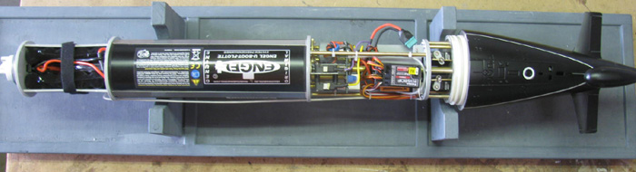
Starboard side
Bottom
Port side
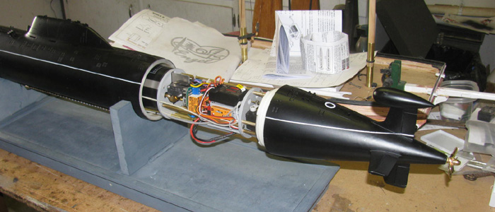
Next will be to fit the electronics tray in to the main hull.
It is suppose to slide in.
But there are warning about scratching the lead ballast bars which
I painted white to help prevent this and stop any corrosion.
Once I am happy with the way the tray fits in to the main hull section,
It will be time for water trimming.
---------------------------
Back out in the shop.
Set up the main hull section on the box lid stand.
The electronics tray slide in half way.
Looking straight on.
I was able to slide the tray all the way in.
It required moving the tray about to get the frames to get over the
bayonet ring and the block up in the front of the hull that the front frame
sits on to carry the weight.
This took all of a couple of minutes to check.
I am going to look and measure where the tray hangs up.
I think a little beveling on the front edge of the frame that is hanging
up will take are of this issue.
--------------
Got back from town.
What to do now?
Went out to the shop.
Well, this will not do.
It's in the 90s at 10:00am.
Right now the boat is on the kitchen table, where I put it every evening.
I am going to check all the controls for proper functioning.
So, all I need to do is bring a few small tools in to the house.
Open up the boat and power the Tx and then the Rx up.
Rudder is centered at neutral.
Check full movement both directions.
A little to much. About 60 degrees.
Watch the rudder at full left while turning the percentage down.
I want to start at 40 degrees
Now do the full right rudder. Good.
Rear Elevators.
Something is not right.
I have more down than up . (Yes I did set all controls at 100% before
starting)
Made changes on Tx.
Still something is not right.
Make note.
Check Main motor forward and reverse.
This motor ESC combination is awesome!
Especially slow speed.
Check ballast tank control.
I read the setup and did what it said to do.
Very basic in that you start with empty tank on control.
Then full, then back to empty to check limit switches.
Now on to something, I have never had.
Does the proportional control work.
I am using a knob control on the Tx.
One click on knob and the ballast motor comes on and moves a very short
distance and stops.
Another click and again the short movement.
2 clicks and the motor moves a little farther than the single click.
I played with this option for 5 minutes going back and forth in steps.
Only think I would like to have is a visual display on the Tx screen
to tell me at what percentage I am at.
I could open the menu to the servo screen which would show me this
information.
Maybe I will do this to learn how much does what. Count clicks from
neutral.
Okay, back to the Rear planes.
What about the auto level feature?
Put the main motor in freezers turning very slowly.
Tip the tray up and down watching the rear planes.
They move as they are suppose to.
On to putting the motor in to forward.
THis is not right.
The rear planes moved to full up.
I have not yet tipped the tray.
Tipping seems to do nothing at all.
Turn control to all stop.
Planes center at neutral.
Reverse still okay.
Forward the same thing happens again.
Well, this is frustrating.
I know.
Read the instruction manual.
That was of no help at all.
Only tells me how to install the Auto leveler.
A thought.
There where lots of loose papers with all the parts.
Out to the shop and start going through the papers.
Wiring diagram.
Main motor ESC information sheet with setup instructions. (Did that)
Oh, look!
And information and instruction sheet for the auto leveler. How about
that.
Took the sheet in the house and out on to the front porch so I cold
be in the bright light to read it.
It talks about a jumper.
(interesting as I found a jumper on my work bench and did not know
what it was for. I taped it in to the parts box I was using during the
build)
The jumper is for setting auto leveler neutral. WHAT?
Read some more.
The jumper goes on the 2 pins that have the wires to the circuit board
that apparently tells the thing which direction the boat motor is going.
Remove the the plug to these wires.
Put the jumper on the 2 pins.
With the Tx on and set at neutral I am suppose to push and hold a setup
button on the auto leveler. (did see that when I installed it)
Plug the power in to the boat system.
Release the button.
Hey, the servo just snapped to a new neutral position.
Re adjust the control rod to get planes set to neutral.
Now test it again.
Reverse on main motor.
Tilt tray and watch rear planes. Moves in correct direction.
Now reverse the main motor and watch the rear planes.
They did not jump to full rise this time.
Tilt the tray and they moved in the opposite direction and correct
to bring boat to level.
Move the tray and the motor direction several more times.
It does what it is suppose to but I do not have correct planes movement.
Too much in the up and not enough in the down.
I go in to the Tx menu and reset to 100% and watch planes movement.
Dial them down to about 35 degrees, up and down.
Recheck auto leveler by tilting tray.
Looks good now.
Check all controls again.
I am now ready to read the instruction on first water test.
Very basic but this boat has a breathing tube.
Need to understand what it is doing and when to plug and unplug.
I think it is a pressure relief valve.
I will let you all know what I learn.
Water testing/trimming tomorrow.
(after reading the instructions. This is my first dry hull boat,
first piston ballast tank, first proportional controlled piston, I am sure
there are other things but there are a lot of first for me to learn.)
============
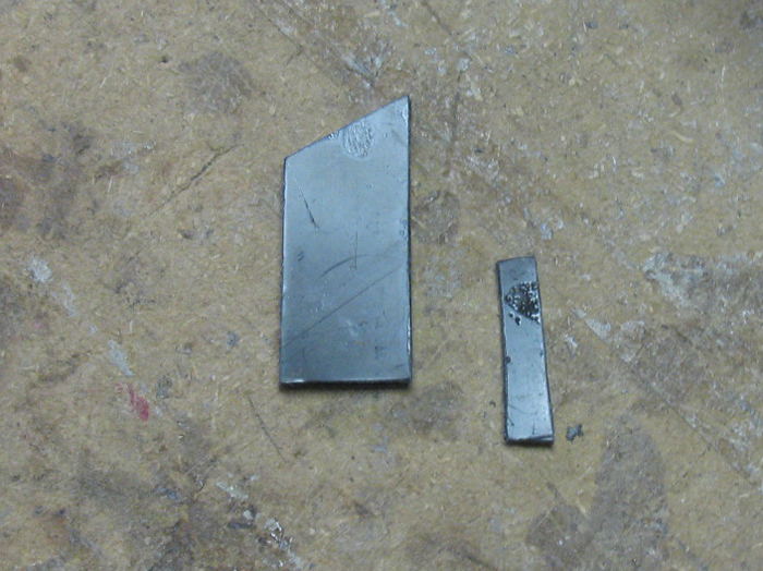
Building clevis to replace one that broke. . . .
This is the original clevis.
The top of the pin broke off and is inside the clevis frame.
No longer works.
Measured the pin to see about getting a replacement at the hobby shop.
Measures .0575" diameter.
Hobby shop said, they do not have metric sizes.
Okay !
Let's see if I can modify this one. or build one out of brass.
The nylon clevis is a press fit on tot he brass tube extension.
Took a bit of effort to twist it off.
That is good as it will not just slide off.
Found a scrap of fuel tubing and cut a clevis keeper.
Found a piece of 1/16" brass rod.
It is too big but I chucked it up in the Dremel and got after it with
a file.
Made a shoulder that was .0574" in diameter. Yep, I took too much off.
But .0004" is not a problem here.
Bent the pin in to an L shape and add a couple of other slight bends.
Parts.
I ground a shallow groove in the top of the nylon clevis for the rod
tail to sit in.
This will keep it from rotating off the clevis.
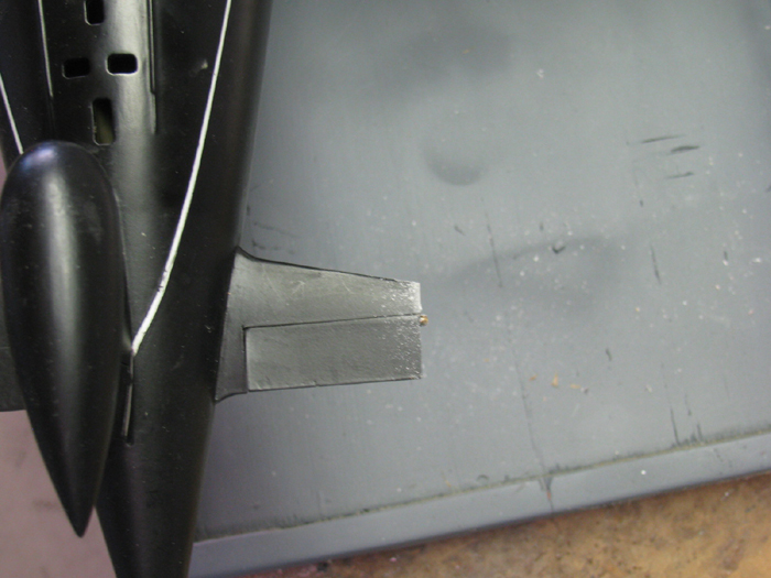
Finished rebuilding of the clevis.
Now all I have to do is get in there on to the rudder horn.
The plan is this.
The pin has a smaller diameter end that goes in to the small hole on
the lower clevis arm.
I made a step from the main pin to the point.
This is so I can lift the pin and set the pin on that shoulder keeping
the clevis open enough to pass over the brass rudder horn.
Once I have it over the hole in the horn or near, I can bump the pin
and it will drop off the shoulder and will have pressure on it until it
drops through and bottoms out in the lower clevis arm.
Turns out, there is not enough room to get two long tweezers in there
and still see what I am doing.
Spent most of the morning trying to make this work.
Finally called it quits!
Option 2, suggested by Tom.
Z bend.
At first I didn't think this would work but as I was messing with the
modified clevis, looking in the tail cone. the Z bend looked like it might
work if I modified the bend 90 degrees.
Made this brass rod with a 90 degree Z bend.
I was able to get it in to the hole of the rudder horn but could not
twist it.
Did some filing on the curve corners and got it to the turn.
Next was to connect this rod to the control rod.
Back to not having enough room for 2 tweezers.
Made a wire hook to help hold the control rod up, level.
Yep, this did not work either.
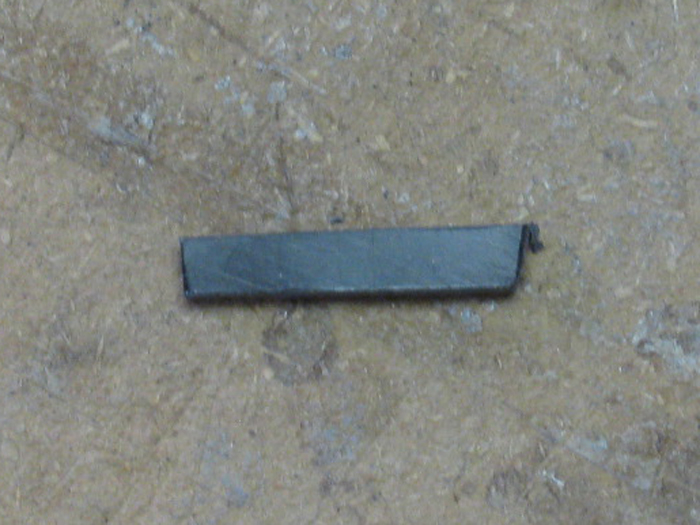
Time to make an old fashion control rod connector.
Solder a wheel collar to one of the rods.
Making sure the wheel collar set screw is pointing in the right direction
when every thing is aligned.
That is a 1/16" wheel collar with t he 1/16" brass rod soldered to
the outside edge in a groove I put on it.
The rod in the boat is less than the 1/16" so there should be plenty
of room.
Yesterday was frustrating if nothing else.
I could get the Z bend rod in there but I could not hold it to put it
in to the wheel collar clamp.
The Z bend wire would turn while I was slipping it in the wheel collar
and that cause it to drop out of the control horn.
I woke up early.
Had some time.
I also had some thoughts on how to make a tool to install the clevis.
I tend to have ideas/possible solutions come to me when I first wake
up.
Went out to the shop and bent up a length of 1/16" brass rod.
In about 5 minutes, I had what I envisioned.
With this wire tool, I was able to hold the clevis (remember the clevis)
and get it on the control horn.
With a second rod that slipped on the first rod to hold it in place,
I was able to open up the clevis to get it over the horn with the brass
pin open enough to clear the horn but still allow enough rod point to feel
for the hole in the horn.
Once the rod point went in to the hole, I removed the spreader rod
and the clevis closed.
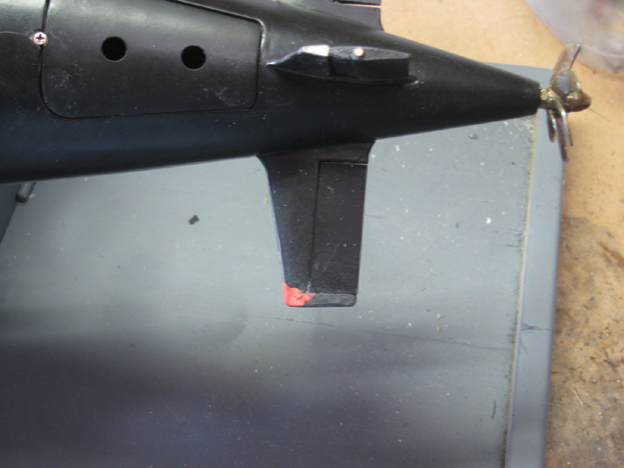
With my flash light, I looked to see if I could see the point sticking
through the clevis.
There is it was.
While holding the clevis steady, I used a thin screw driver to slip
the fuel hose keeper down the shaft of the clevis which hold the clevis
close.
In the photo, I can see the rod tip sitting up through the clevis.
Why did I put the pin through the clevis, bottom to top.
Well, The boat is upside down and when turned over, the weight of the
clevis pin will be going down, helping to hold the pin in position.
====================================================
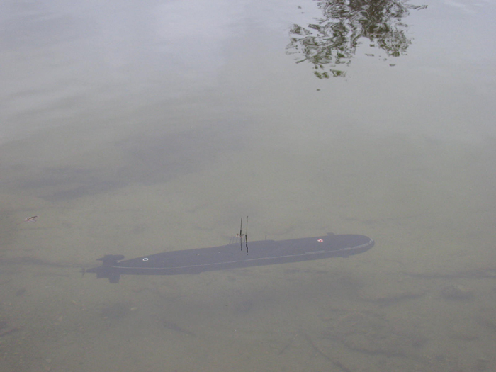
Trimming the boat . . .
I do not have photos of the trimming in progress.
I only have this photo.
Weight is correct.
Balance is correct.
The boat is a little.
I can fix the light by just adding a small weight or as seen in the
photo, I added 2 masts to get the neutral buoyancy with just 2" of the
tall mast sticking above the water surface.
You can see a dark circle around the mast.
That is the water surface.
The part of the mast sticking about the surface is 1/4" of 18" brass
tubing and 1.75" of 1/16" piano wire.
Total height above surface is 2".
Remove 1 mast and the sail sits just below the surface bobbing.
Add 1 more mast (depends on if it is a tall or short mast) and the
boat will drop very slowly to the bottom.
The great news was after moving the internal 1" weight, 4 times, the
boat now hovers, LEVEL.
At this point I was having troubles with the ballast tank motor, running
intermittently.
This is caused by a low battery.
Since I got the boat back in April, I have only changed the 12v battery,
once. (in April)
All testing has been on that one charge.
So the next project is to figure out exactly how my charger works and
program it.
I found a nice video that goes step by step through 4 different kinds
of batteries.
I watched so many times, so I could write down the instructions and
confirm I got them in order.
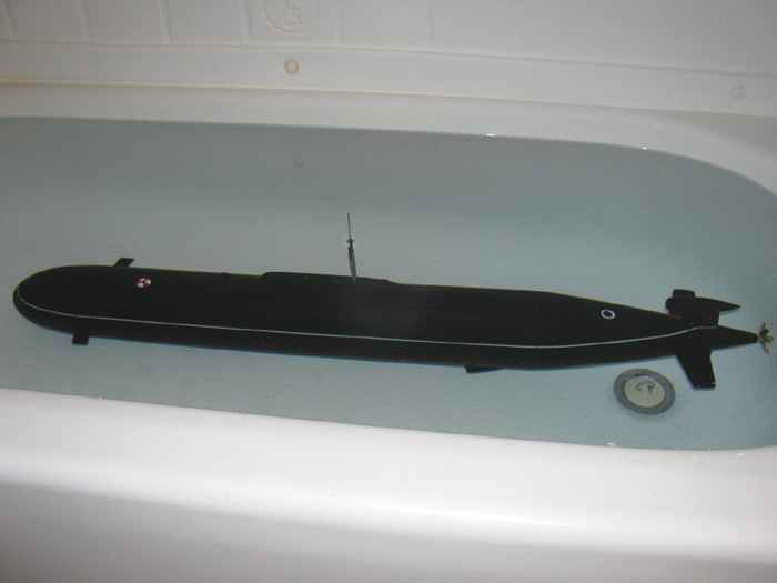
At our local gathering on June 10th, this boat will be there and in
the water.
(Maybe, I should tie a long string on it. What do you think?)
------------------
During the trimming process, I learned that the piston ballast tank
expels enough volume of water to pop the tail cone access hatch off.
Even cleaned off the paint from the magnet.
I was going to use a small piece of clear tape but having the hatch
pop off 6 times, I decided for a more secure solution.
I drilled a very small hole and counter sunk a #2 brass screw in the
seam.
This gives positive retention of the hatch and leaves the magnet in
place.
==================
Thought I would see if I can put the sonar location lines on the hull.
This is my first attempt using 1/32" white tape.
I will do some measuring to see how close to scale these lines are.
I have 1/64" tape if I need to size it down.
I have looked at so many photos showing the hull markings.
Looks like no 2 boats are the same.
And the lines are certainly not straight on the real boat.
I have a backup plan should I not be able to make this lines.
Russia exported Akulas to India.
They do not have the sonar sensor location lines.
Just 4 straight lines on the bow deck and a white small hatch circle
behind the emergency buoy.
Using 1/64" tape.
This looks better to me.
I think I am going to go blind.
I need to straighten a few lines but this is what I have after 45 minutes
of cutting and laying on.
For scale.
Emergency hatch is the size of a US dime.
Or this line is 2 3/8" <---->
I think I have this figured out.
I worked on the rear section and spent 35 minutes, cutting and setting
the strips.
I have the port side sonar location markers on.
I think before I go on, I will mask these marks off and clear coat them.
If it goes badly, I only have one side to deal with.
Size reference.
On my finger is a single vertical stripe.
I have decided to put on the bow sonar location lines.
So here I go.
Here is the bow before the lines.
Having applied the first lower line.
I have not yet trimmed the line or cut out the two vent locations.
The vent locations are incorrect, so I will have to just make
do and try to make the lines look correct.
Top line applied.
Looking at several photos, I found that the two lines are not parallel
at the front of the bow.
They are level but due to the curve of the bow, the two lines get a
little farther apart.
If you were at the water line and looked at the two lines they would
look parallel.
The lines are not exactly straight but from 5 feet away, it doesn't
matter.
After all the diagonal lines are put on, it will be hard to tell.
I can do some adjusting as I put the diagonal lines in place.
Remember these lines are made with 1/64" white tape.
I need to go to town this morning.
I will continue when I get back.
A little more progress.
Measured and cut out the two locations where the vents should be.
I did the Port side and have started the Starboard side.
Port side, not yet trimmed.
Finished the Starboard around the vents location.
I guess it is time to work my way around the bow.
I cut the pieces one at a time and place them using the Exacto knife.
Finished the Port side.
Woke up early.
Decided to do some more sonar location marks.
Coming around the bow.
It will get easier here as the lines are now the same length.
I have all the lines on.
I need to adjust a few before I clear coat.
Not perfect but I am happy with it.
=============================
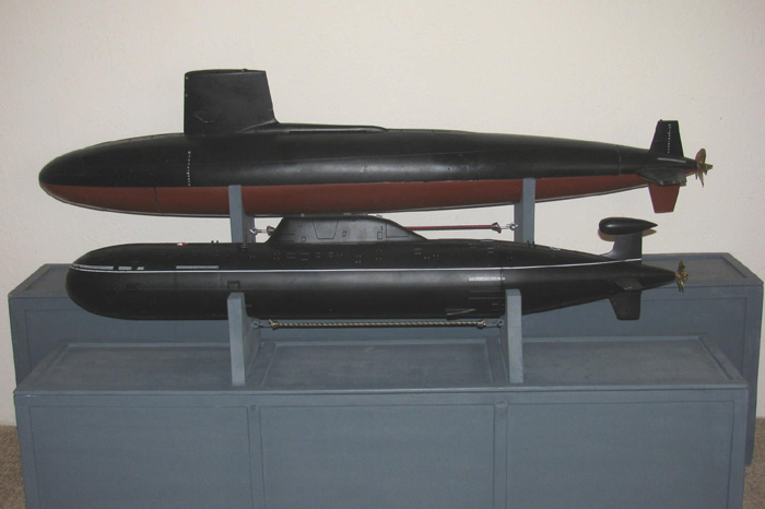
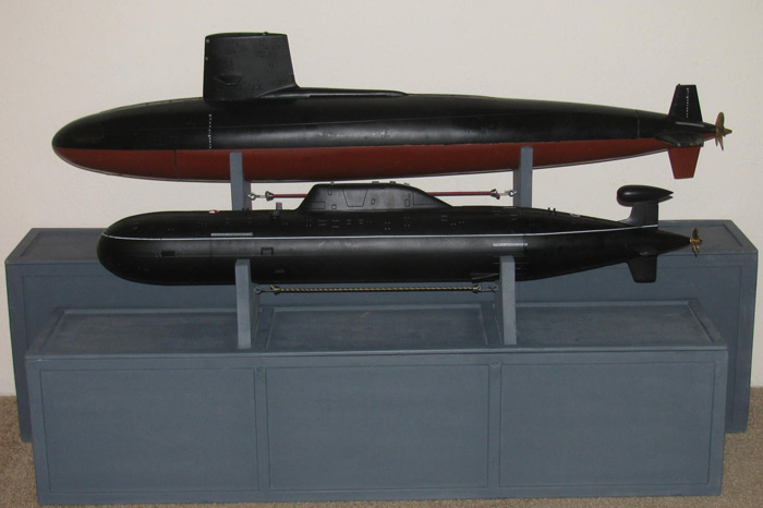
Skipjack and Akula II
=============================
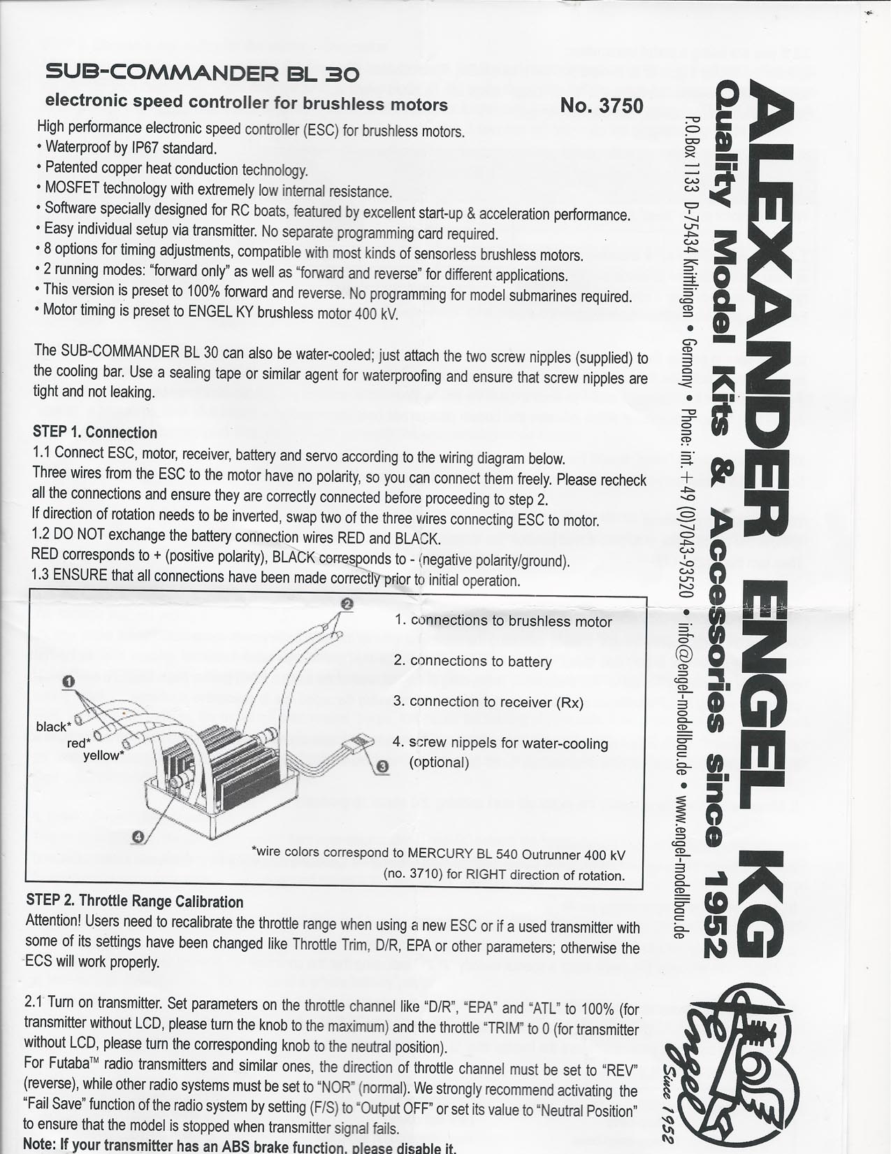
Speed Controller setup instructions....
===================================
The Akula II has been in the pond 3 times.
Everything has worked as it is suppose to.
The surface line is a little low but that could be fixes by removing
a little ballast weight.
Not ready to do that.
The piston tank is now my favorite system.
The only issue I have is the turning radius.
The boat makes big circle.
I asked Mike Dory about his boat which appears to turn just fine.
I opened up the rear hull hatch so I could see the rudder yoke and
where the control rods go through each other.
With Tx in hand, I turned on the Tx and then the Rx.
I moved the rudder back and forth to it's limit.
What I was looking for was the yoke turning and contacting the other
control rod.
I could see, I was not getting full movement of the rudder.
Made the adjustments and was ready for the next pond trip.
At the pond, still the turning radius is big.
Much bigger than I would like to have.
20' or more.
Maneuvering took a lot of care.
Not to my liking at all.
The boat has sat in my living room since then.
I look at it and think about what could be done.
My idea would require modifying the rudder.
Thought about that for a few days.
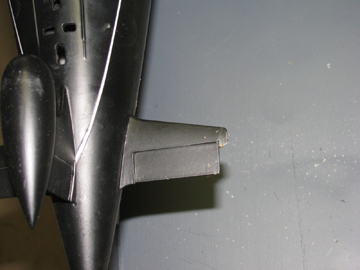
What I decided to do was add to the front of the lower rudder.
About 1/4".
Leave the upper rudder as is for original look.
How many people actually look at the bottom rudder anyway.
With the rudder centered, it is hard to see the modification.
In a couple of weeks, I will be at the pond and will see if this helps.
------------
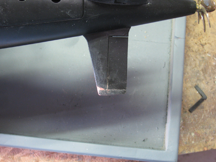
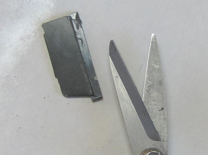
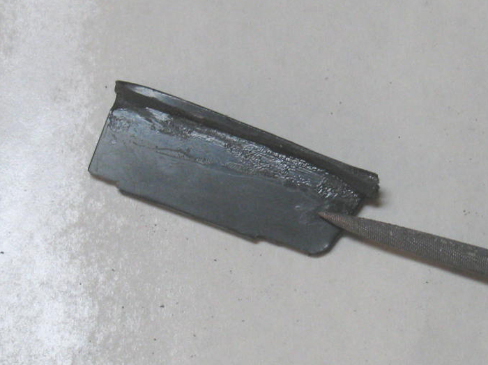
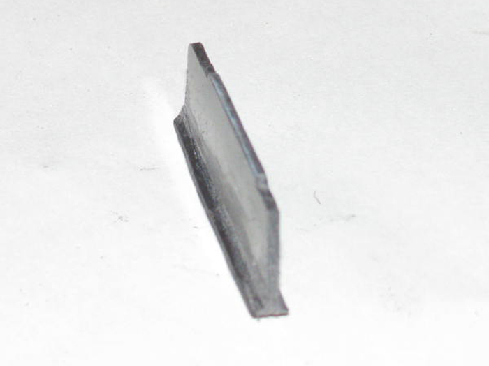
Now, what did I do.
Here is the rudder as originally built.
3 plastic strips to make the rudder extension.
They were cemented together to make a 3/16" thick by 1/4" wide strip.
If you are squeamish, you may not want to look.
I am going to drill some holes in the rudder stab.
3 holes made an opening large enough to get my 1/4" jeweler files through.
Using a rough 1/4" round file, I started enlarging the hole.
I used my calipers to scribe a line at 1/4" from the rudder front edge.
This was my stop mark.
After about 45 minutes using a 1/4" round file and a flat file,, this
is what I have.
I shaped the 3 pieces of plastic to an air foil shape with a rounded
groove on the back side to fit over the rudder front edge.
Took the time to sand and file until I had a good fit in the opening.
Left a 1/64" gap for rudder to pass through.
It is probably more after the rudder was bonded in place.
Filed the joint where the rudder and new part was attached.
Was very close to being flush.
A little glaze to make the joint smooth by sanding after it cures.
Final sanding completed.
Getting ready to paint.
Masking off the hull.
Painted flat black.
3 coats applied and curing.
Clear coat applied.
Masking tape and paper removed.
Still shinny because it is still wet.
After it dries, I will see if I can get a better photo.
Rudder modification completed.
===============================
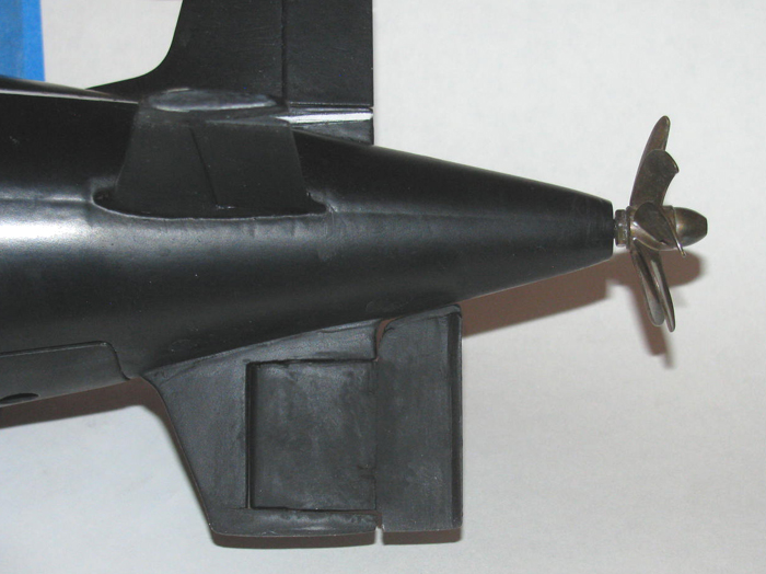
Bow Planes issue.
Every time I take this boat to the lake, one or the other bow plane
gets knocked off.
The hull is a dry hull so there is no rod, pins or anything going through
the hull to attach the planes to.
The planes are surface attached with glue.
The planes are ridge.
My boat runs fine with only one plane but I am thinking of removing
them both.
But I have 2 events I want to go to before making any changes as the
boat runs really well right now.
Of the options I have thought about, the latest one may have real possibilities.
Magnets. Strong small earth magnets.
Will need to do some testing but I think 2 small square magnets in
each plane and two inside the hull will keep the planes on or with the
boat.
First thought is to have the bow planes attached magnetically while
on the bench or table.
Then remove them when the boat goes in the water.
I just ran out to the shop and did a quick magnet test with magnets
I use on my sail planes linkage for the Skipjack.
These magnets are about 3/16" in diameter.
They are jewelry magnets.
4 to the package for less then $2. (Hobby Lobby)
The distance between the magnets was necessary because any closer they
jumped to each other and connected.
Top is 2 magnets together.
Bottom are the 2 separated.
I held one magnet inside the hull against the hull.
Then I passed another magnet over the outside of the hull and bang.
The magnet jumped in to place over the inside magnet.
Did this several times from different directions.
Same results.
Get it close and it takes over.
Next I tipped the outside magnet over and it popped right back in place.
I move the magnet farther away and up to 3/4" the magnets jumped together.
So, I am thinking that if I use 2 magnets per bow plane, they might
get knocked over but would not leave the boat and would actually reset
in correct position.
Got to find some magnets about 1/8" square.
================
Possible mounting of bow planes on transportation box stand.
================
9/10/18 Repair Log - Yep, damage.
On 9/8/18 there was a Fun Run for SubRonLA.
It was to make sure everything was good to go to San Francisco 2 day
event on the weekend of the 2nd.
I run my Akula II for about 3.5 hours.
I had a Tx battery fail on me after about 1 hour.
It had been charged the day before.
I number my batteries so I can keep track of them when used.
Turns out the battery is one I got with a used Futaba 9 CAP Tx last
year.
My spread Sheet told me that the battery was questionable.
As the battery was failing, rather quickly, I brought my boat in near
the dock.
About 2 feet out.
I set the Tx down and walked over and got the back battery.
Opened the Tx and replaced the battery.
The tx showed that the battery was up.
I ran for another 2.5 hours of so.
Most of my running was static diving to get use to the new controls
on the F14 Tx.
The ballast control is so sensitive that I swear if I look at the knob
and think dive the boat will go down 1/2".
If I touch the knob the boat goes down about 2".
I ran the boat for more than an hour, only touching the rear planes
control to keep the boat at periscope depth.
That is 1" or less of the tip of the scope showing.
And for reference, I was making big circles in the lake.
Big, out to about 150' + way from the dock.
Back to the repairs.
After about 3.5 hours, I had had enough.
I bought the boat in and with my new light weight hand cart, I lifted
the boat out of the water and backed up a few steps so I could get in front
ot pick up the boat.
While backing up, I looked behind me to see where to step.
That little motion allowed the boat to slid off the cart.
Being new, I had not installed a skid resistant surface on the cart.
The boat slid off stern first.
I picked up the boat and moved it to the bench.
I noticed the right bow plane was missing.
I had left the cart where the boat slid off.
I found the bow plane in seconds.
Back at the bench, I noticed that the right rear plane support was missing.
Next day at home, I took the boat out to the shop where I have a jig
for putting the bow planes.
It is the boat stand and I made a couple of pieces to hold the boat
level and the bow planes in place while CA ing the planes back on.
Set the boat on the stand and place the two jigs.
Put a couple of drops of CA on the plane and put it in place.
Total time was about 2 minutes.
While hold the plane in place I gave it a little shot of kicker on the
top.
Now I do not have to hold it.
Wipe the excess kick off and all it needs is to cure and a little touch
up paint.
Then I noticed a real problem.
The right side stern plane support was broken right at the hinge rod.
I thought about trying to add and end piece to the existing tip.
Not much to work with because most of the part at the rod is hollow.
Looking closely at the plane tip, I can see where the tip was added
to the plane.
The stabilizer is basically capped.
I did this to the Skipjack but used small screws so I could remove
the planes.
So my plan is to cut the rest of the tip off and make a new tip.
Get some scrap plastic and start making the part.
Sand them and the apply cement.
Put in vise and clamp very tight.
Letting the cement cure, I cut the tip off the stabilizer.
Shape the tip to fit the stabilizer.
Drill a hole for the plane control rod hinge.
This part is less than a 1/4" tall.
There is only 3/8" to bond the cap on to the stabilizer.
Making sure the two surfaces are flat was critical.
I put a lot of cement on the cap part.
Let it sit and then apply again.
This makes the plastic soft.
Put a couple of drops on the stabilizer and press the two parts together.
The part being soft will form to the stabilizer with pressure.
I put 2 layers of tape on the top of the plane to give clearance.
I let it cure for a couple of hours and then I glazed it.
Notice the top of bottom rudder stabilizer has the cap cut off here.
Here the glaze has set over night.
Finally filed it and sanded with 200 grit.
Ready for touch up painting.
Moved on to the lower rudder.
Did the same thing.
Make the part from plastic pieces.
Shaped it.
Drilled control rod hinge hole.
Cemented it in place.
Will let it cure until tomorrow and then file and sand it. (Glaze as
needed)
By noon tomorrow, the repair will be completed and the boat will be
ready to go to San Francisco.
==============================
Notes:
Ballast weight locations and sizes.
A. 10 1/2" long. Set back from hull edge. 4 3/8".
B & C. 13" long. set back from hull edge. 3 1/4"
D. 10 1/2" long. Set back from hull edge. 4 3/8".
E. Weight is 1 3/8" wide and 1" deep. 1/4" gap between E and B
& C.
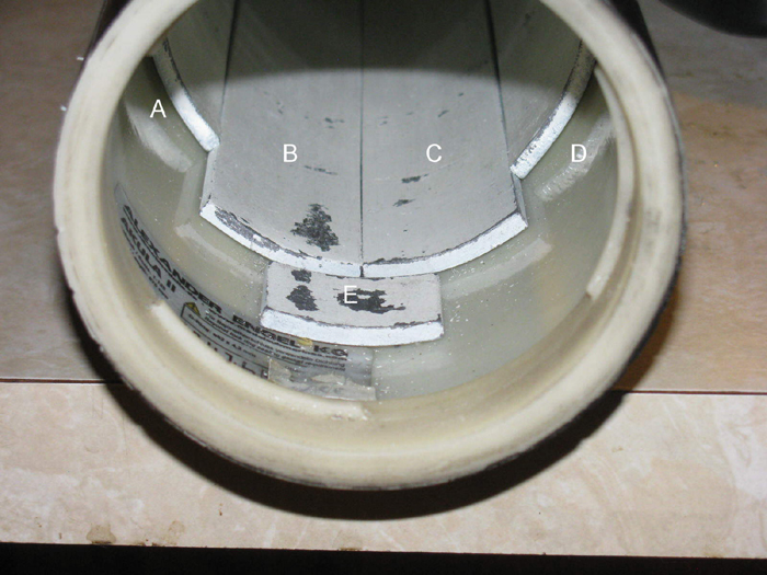
This weight was used to adjust fore and aft pitch and it rolled the
hull upright removing list.
It was moved several times.
February 7th
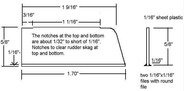
Rudder modification #2.
Here is the new rudder extension installed.
Started with sheet plastic 1/16" thick.
I cut a strip, 5/8" wide and about 3" long.
I cut a second strip from scrap about 1/2" wide and 3" plus long.
The main rudder piece (on right) is cut square and then the top is
cut on an angle to match the rudder to hull line.
The smaller strip is cut in half to make the two fish tail parts.
I sanded one edge on both strips to about 45 degrees.
I filed notches on the side that will attach to the original rudder.
These notches are so the new piece clears the rudder skag at top and
bottom.
New extension.
I use plastic cement to attach one of the fishtail pieces to the rear
edge of the rudder.
The plastic is 1/16" thick and I place the piece on the rudder ao the
outside edge of the angle is lined up with the trailing edge of the rudder.
About 1/16" plus over lap.
Once the cement cures, I trim the fishtail piece near flush with the
rudder trailing edge.
Install second fishtail piece to rudder.
Trim when cured.
Flat sand on bench top the trailing edge of rudder.
I then use a half round file to clean up the Fishtail to rudder.
The new rudder extension is mounted to the original rudder using two
.0032" piano wire pins.
1/4" in the original rudder and 1/4" in the new extension.
I wanted to make the extension removable.
I used a couple of different methods to attach the extension to the
rudder.
The first failed.
I decided to attach the extension permanently with CA glue.
I can always cut the extension off with a razor saw if I need to.
I covered the piano wire with CA and pushed the pins in to the extension
piece.
Next I applied CA to the pins and along the front edge of the extension.
Quickly pushed the pins in to the original rudder and held straight
with my fingers.
(licked my fingers to reduce getting my fingers stuck in the
glue)
After the glue set, I then applied a drop or two more CA on the seam
between the extension and rudder.
With wetted finger, I smoothed out the glue drops in to the seam.
Did both side.
After curing, I files both sides smooth.
Added a little more A in low spots.
Filed again.
Looks good, painted flat black after taping of the area to stop over
spray on the hull.
Drawing of rudder extension.
October 21st ====2020===========================================
It has been a long time since I posted about the Akula II.
I decided to go to the lake this Saturday. Oct 24, 2020.
I chose the Akula II to run.
Why? It was the last boat I ran and should require the least preparation
to get ready to go.
Put the Tx batteries on the charger.
Opened up the Akula II. (An Engels dry hull boat)
Took the boat batteries out and set next to the charge waiting their
turn.
Looking over the hull o-ring seal.
All looks good.
Just the normal silicone grease at the lake on the o-ring and it should
be ready to go.
While looking the electronics tray over, I notices something I had not
seem before.
The ballast tank intake and outlet hose has crud in it.
The clear tube on the right end of the tray.
This tube has about 3" of brown crud in it.
It appears there might be some water in the hose from the last time
I ran the boat which has grown crud.
I will clean the crud out of the hose by removing the hose from the
system.
This tells me, I need to do a better job of flushing out the water from
the ballast tank after running the boat.
Maybe a few drops of bleach to kill the living stuff in the water and
then flush the ballast tank with clean water.
AND tip the hull on end to get all the water out of this hose before
storing it way until the next time I run it.
October 24th ===============================================
I made it to the lake about 7:15am.
Had my Akula II in the water about 7:30am.
I spent about an hour trimming the boat.
I started by diving the boat and surfacing about 3 thimes to get all
the air out of the piston ballast tank.
This is done about 2 feet from shore just inc ase I have to go in after
the boat.
Here the boat is on the surface.
Submerged down to the top of the sonar bulb on the rudder.
Submerged down enough to cover the sonar bulb.
Continued down to periscope depth.
Down and hovering at about 12' below the surface.
What I was looking for was the fore and aft trim (pitch) at different
depths.
The boat, from the surface to the bottom was level.
This was very good.
After doing this over and over for about 30 minutes or so, it was time
to drive the boat out and back, at different depths.
What I was looking at while doing this was the heel of the boat.
Last time out, I noticed the boat leaned to the starboard side. (right)
Seeing how the boat leaned, I would take the boat out of the water
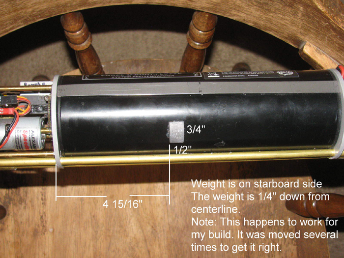
and open it up.
Move a small lead weight I have mounted on the side of the ballast
tank piston cylinder.
The weight is small.
1/8" x 1/2" x 1/2"
Mounted with a small amount of silicone, it easy to twist it off.
Clean the silicone off the tank and remount the weight in a different
place.
Because the boat is trimmed in pitch, I only had to move the weight
vertically on the tank.
I did this problem 6 or 7 times.
I have it very close and decided to leave it.
I think just the placement of the battery wires will change this trim.
Now I can run the boat.
In the lake where we run boats is a small cover.
Maybe 75' across and then out to the big part of the lake.
There is a aerator out about 100'.
Try to stay away from that thing.
I run at periscope depth for an hour or two.
Did some surface running.
Did some down to the middle of the sail running.
Came in close and did some fully submerged runs past my chair.
Can't go too deep in this area of the lake.
There are weeds down about 18" or so.
Managed to stay out of the weeds today.
Then the problems happened.
I do not carry a phone or a watch.
So I have to guess on the time.
My guess is the boat ran about 3.5 hours and maybe a little more with
out being turned off.
Now the problems.
I am running at periscope depth as I turn out towards the right side
of the aerator.
All of a sudden, the boat pops to the surface.
? Why did it do that?
While thinking and moving controls, I notice I do not have main motor
any more.
I still have rudder and planes as I can see the rudder moving.
I thought about operating the ballast system but also thought what
if it works going down but not going up.
I changed the battery in the TX.
Still no main motor.
Boat has come to a stop about 100'+ from shore.
There is no wind. (normal early in the morning.
So I planned to sit and wait for the morning wind.
The boat was moving towards shore very slowly.
Using a background tree across the lake, I could see it moving.
The fear is the wind will come up and blow towards the other side which
is about 400' out and a long walk around the big lake which is about 1
mile long.
I decided to sit down and be patient.
After what seemed to be 30 to 45 minutes the boat came close enough
to shore to get my radio antenna (off the Tx) on to the rudder.
A little pull and boat came to shore.
Reached down and lifted my boat out to safety.
What I learned? 2 things.
Have a watch to time the run so I stop before the battery BEC kicks
in.
Take a second boat even if I do not plan to run it.
This would have given me a rescue boat to push the Akula II in to shore.
This is not a problem when running with others.
But I was alone today.
It was a very good day at the lake.
I got needed trimming completed.
The boat ran well right up until I ran the battery down.
I learned some thing s to do before going to the lake.
MY boat did not sink and made it back to shore.
At really good day.
A passerby asked if I had a spare battery?
I said I do but until the boat reaches shore I can not use it.
|